


ENGINEERING
DESIGN GUIDE
HTV/HTD/HTH Series
Two-Stage
Geothermal Heat Pumps
2 to 6 Tons
Heat Controller, Inc. • 1900 Wellworth Ave. • Jackson, MI 49203 • (517)787-2100 • www.heatcontroller.com

Engineering Design Guide |
HTV/HTD/HTH SERIES |
Heat Controller, Inc. |
|
|
|
Model Breakdown
Model nomenclature – Two Stage geothermal heat Pump
P = Back
W = Straight
H = Horizontal
J = Cupro-Nickel
HTH
HORIZONTAL
LEFT RETURN AIR
|
|
Piping End |
|
Piping End |
Left Return Air |
Piping End |
Left Return Air |
|
Back Discharge |
|
Side Discharge |
RIGHT RETURN AIR
Piping End |
|
|
|
Right Return Air |
Piping End |
Right Return Air |
Piping End |
Back Discharge |
|
Side Discharge |
|
1

Heat Controller, Inc. |
HTV/HTD/HTH SERIES |
Engineering Design Guide |
|
|
|
Two Stage Geothermal Heat Pump Systems
Features of the Two Stage HT Series
The HT Series Geothermal Heat Pumps are some of the most efficient and innovative geothermal units on the market today.
Packed with features, they offer the best value to the homeowner who is interested in quiet comfort and low operating costs as a result of extraordinary efficiencies.
Technically, the HT Series are state-of-the-art with digital electronic controls, multi-stage scroll compressors, computer controlled fan motors, zero ozone depleting refrigerant, and much more.
Design Features
•Five capacities to meet all application requirements—two, three, four and six ton models.
•Efficient operation from 20°F to 120°F entering water temperatures. Flow rates may be as low as 1.6 gpm/ton.
•Top supply air discharge accommodates upflow applications.
•Select left or right hand return air positions for all models; cabinets include a deluxe filter rack/duct collar.
•Variable speed ECM blower motor adjusts to multiple duct system applications and provides soft start for added comfort and quiet operation.
•Narrow cabinet design can be easily moved through doorways.
•Internally trapped condensate piping (on all vertical units) allows easy, compact installation.
•Internal electric heat unit (optional) is designed for easy field installation.
•Electric box is positioned for easy field wiring from two sides.
•Loop pump power block is built with circuit breaker.
•Coaxial low temperature protection can be selected in the field for well or closed loop installations.
•Air coil low temp. protection utilizes high accuracy thermistors.
•Coaxial heat exchanger, refrigerant suction lines, hot water generator coil, and all water pipes are fully insulated to reduce condensation in low temperature conditions.
•Isolation mounted compressors and low RPM blowers are used to reduce noise; compressor compartment and interior cabinet are insulated with 1/2" coated glass fiber insulation.
•Double isolated compressor delivers extra quiet operation.
•Safety features include: high pressure and loss of charge protection for the compressor; condensate overflow protection; low temperature protection sensors to safeguard the coaxial heat exchanger and air coil; hot water high-limit hot water generator pump shutdown; fault lockout that enables emergency heat and prevents compressor operation until thermostat or circuit breaker has been reset.
Operating Efficiencies
•AHRI/ASHRAE/ISO 13256-1 ratings for heating COPs and cooling EERs are industry leaders.
•Hot water generator (HWG) with internal pump generates hot water at dramatic savings while improving system performance.
•Efficient scroll compressors provide quiet, reliable operation.
•Oversized coaxial tube water-to-refrigerant heat exchanger delivers high efficiency and extra heating capacity; convoluted water tube functions efficiently at low flow rates and provides resistance to freeze damage.
•Oversized rifled copper tube/lanced aluminum fin air-to-refriger- ant heat exchanger offers high efficiencies at low air velocity.
•Large, low RPM blower is both quiet and efficient, and provides high static capability.
Service Advantages
•Three removable access panels for the compressor compartment and one or two (depends on model) for the air handler compartment offer quick access to all internal components even with ductwork in place, making the unit service-friendly.
•Built with bi-directional thermal expansion valve.
•Brass, swivel water connections make it easy to connect loop and hot water piping.
•Insulated divider and separate air handling/compressor access panels allow service testing without air bypass.
•Design allows in-place service in tight installation spaces.
•CXM control features LED status light with memory feature for easy diagnostics.
•Control box and fan motors have quick-attach wiring connections for fast removal/reconnection.
•Biflow liquid line filter drier is factory-installed.
•75 VA control transformer comes with circuit breaker.
•Internal drop-out blower assemblymakes servicing simple.
•Refrigerant circuit includes high and low pressure service ports.
•E-coated refrigerant-to-air coil helps protect the coil from corrosion and extends life expectancy.
Factory Quality
•All units are built using our state-of-the-art manufacturing system that is designed to assure quality of the highest standards. This system:
-Verifies that the correct components are being assembled; -Automatically performs special leak tests on all joints; -Conducts pressure tests;
-Performs a highly detailed run test;
-Automatically prevents a "failed" unit from being packaged for shipment;
-Creates a computer database of run tests for future service analysis and diagnostics;
-Includes painting heavy gauge steel cabinets with durable epoxy for a long-lasting finish;
-Performs all refrigerant brazing in a nitrogen-rich environment;
-Evacuates units to a deep vacuum of less than 50 microns prior to refrigerant charging
-Halogen leak tests all joints to ensure a leak rate of less than 1/4 ounce per year.
Options & Accessories
•Optional internal auxiliary electric heat.
•Electronic auto-changeover thermostats with indicator LEDs.
•Closed loop flow controller and hose kits.
See Geo Accessories brochure for complete list of accessories.
2
Engineering Design Guide |
HTV/HTD/HTH SERIES |
Heat Controller, Inc. |
|
|
|
Heat ControllerTwoGeoMaxStage Geothermal2 n GeothermalHeat PumpHeatSystemsPump Systems
What’s1>7J INew(;M M?J> theB?C7J;'7IJ;HHT series?I .H7DGK?B?JO W
, {£ä Ê,ivÀ2 |
}iÀ> Ì |
|
||
|
(*! +(HFC-410A |
(" ( %* |
|
|
, {£ä ÊÃÊ>Ê V À iÊL>Ãi`]Ê {£ä ]Ê |
|
|||
|
HFC7HJ>*KH;-410AZis?Ia7 DED 9>BEH?D; 87I;: #! H;<H?=;H7DJ J>7J |
|||
R-410A is a non-chlorine-based refrigerant with |
|
|||
ÀivÀ}iÀ> ÌÊÜÌ ÊâiÀ Ê â iÊ`i«iÌ Ê> `Ê ÜÊ} L>ÊÜ>À }Ê« Ìi |
||||
zeroM?J>ozone, depletion7D: , and low?I I;;Dglobal7IwarmingJ>; <KJKH; E< 7BB H;<H?=;H7DJI |
||||
М>°КК МКГКГii К>ГКМ iКvХМХАiК> К |
|
|||
potentialKI;: MEHB:M?:; |
|
|||
АivА}iА> МГКХГi`КЬ А`Ь`i° |
|
|||
|
#! 9>7H79J;H?IJ?9I 9ECF7H;: JE , 7H; |
|
||
, {£äÊV >À>VÌiÀÃÌVÃÊ>Ài\ |
|
|||
|
Q ?D7HO 7D: D;7H 7P;EJHEF?9 C?NJKH; E< , 7D: |
|
||
UÊÊ |
i>ÀÊ>âi ÌÀ «VÊ ÝÌÕÀiÊ vÊxä¯Ê, ÎÓÊ> `Ê |
|
||
Ê |
|
, |
|
|
|
xä¯Ê, £Óx° |
|
||
|
Q #?=>;H ;<X9?;D9?;I >?=>;H EF;H7J?D= FH;IIKH;I |
|||
UÊ6ÀÌÕ> ÞÊ Ê} `i° |
|
|||
|
Q 4;HE EPED; :;FB;J?ED FEJ;DJ?7B 7D: BEM =BE87B |
|
||
UÊxä Èä¯Ê } iÀÊ «iÀ>Ì }Ê«ÀiÃÃÕÀiÃÊÌ > Ê, ÓÓ° |
|
|||
|
|
M7HC?D= FEJ;DJ?7B |
Ê |
|
UÊÊ Ì Õ} Ê>ÊL >ÀÞÊLi `ÊÌ iÊÌÜ ÊV « i ÌÃÊ >ÛiÊÊÊ |
||||
Ê |
Q 0?HJK7BBO DE =B?:; /DB?A; EJ>;H 7BJ;HD7J?L; H;<H?=;H7DJI J>; |
|||
|
М iКГ> iКi> КА>Мi°К ГК>КАiГХМКАivА}iА> МКV> КК К |
Ê |
||
Ê |
|
JME 9ECFED;DJI ?D #! >7L; L?HJK7BBO J>; I7C; B;7A |
||
|
LiÊ>``i`]ÊvÊ iViÃÃ>ÀÞ]ÊÜÌ ÕÌÊÀiV ÛiÀ }ÊÌ iÊ |
|
||
Ê |
|
H7J;I .>;H;<EH; H;<H?=;H7DJ 97D 8; 7::;: ?< D;9;II7HO M?J>EKJ |
||
|
V >À}i° |
|
||
|
|
H;9EL;H?D= J>; 9>7H=; |
|
|
0 # * 1 #* ( |
|
|
BB .H7DGK?B?JO W KD?JI ?D9BK:; 7 |
|
|
<79JEHO ?DIJ7BB;: U XBJ;H H79A :K9J 9EBB7H |
|
|
M?J> 7 U FB;7J;: >?=> ;<X9?;D9O ' ,0 |
|
|
7?H XBJ;H .>; ' ,0 C?D?CKC |
<4AE %% |
|
;<X9?;D9O H;FEHJ?D= L7BK; F;H -#, |
|
|
|
|
|
-J7D:7H: :;I?=D <;7JKH;I KBJH7 |
|
|
BEM L;BE9?JO <FC <EH ;NJ;D:;: XBJ;H B?<; BEM FH;IIKH; :HEF |
||
S ?D M= 7D: >?=> F7HJ?9KB7J; ;<X9?;D9O I?P; |
|
|
7D: .>; FB;7J;: :;I?=D 7D: BEM L;BE9?JO |
||
9EC8?D; JE 7BBEM J>; XBJ;H JE IJEH; 7 B7H=; 7CEKDJ E< :?HJ 7D: |
||
H;IKBJ ?D 7 FH79J?97B H;FB79;C;DJ B?<; E< KF JE CEDJ>I |
|
|
Electro& * "( &"#deposition-Coated Air Coil
BB HTB?C7J;'7IJ;HSeries .H7DGK?B?JO W -;H?;I
Ê /ÊÃiÀiÃÊ `iÃÊvi>ÌÕÀiÊ> Êi V >Ìi`
CE:;BI <;7JKH; 7D ; 9E7J;: 7?H 9E?B .>?I
>À V °Ê/ ÃÊ iVÌÀ `i« ÃÌ Ê«À ViÃÃÊ
;B;9JHE 9E7J?D= FHE9;II M?BB FHEL?:; O;7HI E<
Ü Ê«À Û`iÊÞi>ÀÃÊ vÊ«À ÌiVÌ Ê>}> ÃÌÊ
FHEJ;9J?ED 7=7?DIJ 9EHHEI?ED <HEC 7?H8EHD;
V ÀÀ Ã ÊvÀ Ê>ÀL À iÊV i V>ÃÊ
9>;C?97BIÀiÃÕÌ }ÊvÀH;IKBJ?D=Ê `iÀ<HECÊLÕ CE:;HD` }Ê >ÌiÀ8K?B:?D=>Ê C7J;H?7BÕÌÊ}>ÃÃEKJ}Ê>=7II?D=`Ê ÃÌÊi7D:ÛCEIJÀ i;DL?HEDC;DJ7BÌ>Ê 9>;C?97BI <EKD: ?D J>; 7?H 'E:;HD 8K?B:?D=
C7J;H?7BI IK9> 7I 9EKDJ;H JEFI YEEH 9EL;H?D=I F7?DJI 7D: EJ>;H C7J;H?7BI 97D TEKJ=7IU 9>;C?97BI ?DJE J>; >EC;VI 7?H -EC;
E< J>;I; 9>;C?97BI 7H; IKIF;9J;: E< 9EDJH?8KJ?D= JE 9EHHEI?ED ?D J>; 7?H 9E?BI <EKD: ?D 8EJ> JH7:?J?ED7B 7D: =;EJ>;HC7B >;7J?D= 7D: 9EEB?D= ;GK?FC;DJ EHHEI?ED E<J;D H;IKBJI ?D H;<H?=;H7DJ B;7AI 7D: ;L;DJK7B <7?BKH; E< J>; 7?H 9E?B 9EIJ?D= >KD:H;:I E< :EBB7HI JE H;FB79; -JK:?;I >7L; 7BIE I>EMD J>7J J>;I; 7?H 9E?B 9E7J?D=I ?CFHEL; CE?IJKH; I>;::?D= 7D: J>;H;<EH; ?CFHEL; 7 KD?JVI CE?IJKH; H;CEL7B 97F78?B?JO H;IKBJ?D= ?D 7 CEH; 9EC<EHJ78B; >EC;
.>; .H7DGK?B?JOT Series W -;H?;I ?I OEKH 7IIKH7D9; E< 8EJ> C7N?CKC 7?H
9E?B B?<; 7D: 9EC<EHJ
&' # % (# &$'( ))&(
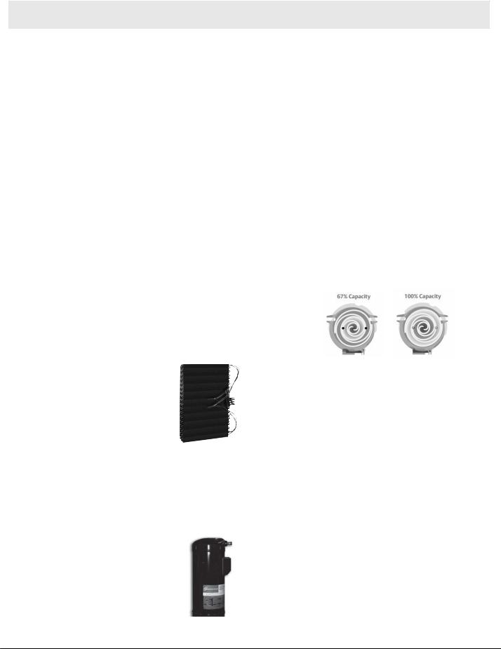
9>?;L; 7 =H;7J;H B;L;B E< 9EC<EHJ .>;EF;B7D: -9HEBB /BJH7.;9>W FHEL?:;I IKF;H?EH 9EC<EHJ ÌJ>7DfixedXN;:-capacity97F79?JO compressors9ECFH;IIEHI 8Oby ?D9EHFEH7J?D= 7 H;LEBKJ?ED7HO JME IJ;F :;I?=D 1?J> 7 KD?GK; F7HJ BE7: 97F79?JO IJ;F IOIJ;CI M?J> /BJH7.;9>W C7?DJ7?D FH;9?I;
J;CF;H7JKH; B;L;BI 7D: BEM;H H;B7J?L; >KC?:?JO .>?I ;B?C?D7J;I KD;L;D F;7AI 7D: L7BB;OI 7D: 7BBEMI <EH IJ;7:O 9EEB?D= 9EC<EHJ #EC;EMD;HI DEM >7L; 7 8;JJ;H CEH; ;<X9?;DJ M7O JE FEM;H J>;?H >;7J?D= 7D: 9EEB?D= IOIJ;C H7?I?D= J>;?H B;L;B E< 9EC<EHJ M>?B; BEM;H?D= ;D;H=O 8?BBI -E M>;D OEKH 9KIJEC;HI D;;: 7 D;M >;7J?D= 7D: 9EEB?D= IOIJ;C C7A; IKH; ?J >7I J>; 8;IJ J;9>DEBE=O ?DI?:; S J>; EF;B7D: -9HEBB /BJH7.;9>W 9ECFH;IIEH
-7L; M?J> IKF;H?EH ;<X9?;D9O )L;H E< IKCC;H KJ?B?JO 8?BBI 97D |
9EC; <HEC J>; 7?H 9ED:?J?ED;H 9ECFH;IIEH EF;H7J?ED IOIJ;C |
M?J> J>; EF;B7D: -9HEBB /BJH7.;9>W 9ECFH;IIEH :;B?L;HI >?=>;H |
;<X9?;D9O J>7D 7DO EJ>;H I?D=B; 9ECFH;IIEH IOIJ;C $D <79J IOIJ;CI |
M?J> /BJH7.;9>W FHEL?:; KF JE =H;7J;H ;D;H=O ;<X9?;D9O 7I |
9ECF7H;: JE £13Î- , IOIJ;CI S M>?9> 97D I7L; >EC;EMD;HI |
>KD:H;:I E< :EBB7HI 7 O;7H ?D ;D;H=O 9EIJI |
.7A; ?J ;7IO M?J> GK?;J;H 9EDJHEB EF;B7D: -9HEBB /BJH7.;9>W ?I H;C7HA78BO GK?;J 7J 8EJ> <KBB 7D: F7HJ BE7: 97F79?JO $D <79J I?J ?I KF JE <EKH J?C;I GK?;J;H J>7D 7 H;9?FHE97J?D= 9ECFH;IIEH #EC;EMD;HI 97D ;D@EO ?JI IKF;H?EH ;<X9?;D9O 7D: 9EC<EHJ M?J>EKJ >7L?D= JE >;7H J>; EF;H7J?ED
&;7HD J>; 8;7KJO
E< J>; :;I?=D 1?J>EF;B7D: -9HEBB /BJH7.;9>W JME ?DJ;HD7B 8OF7II FEHJI ;D78B; J>; IOIJ;C JE HKD 7J F7HJ BE7: 97F79?JO <EH 8;JJ;H ;<X9?;D9O 7D: >KC?:?JO
9EDJHEB 7I;: ED :;C7D: J>; CE:KB7J?ED H?D= ?I 79J?L7J;: I;7B?D= J>; 8OF7II FEHJI 7D: ?DIJ7DJBO I>?<J?D= 97F79?JO JE .7A; 7:L7DJ7=; E< TI>?<J ED J>; YOU IJ7=; 9>7D=?D= DE IJEFF?D= 7D: IJ7HJ?D= H;GK?H;: B?A; EJ>;H JME IJ7=; 9ECFH;IIEHI
7>EEI;iÊ FHEL;D«i> `ÊI9HEBB-VÀ F;H<EHC7D9;Ê1ÌÀ>Ê/iV ÒÊLÕ1>?B;`ÃÊEF;B7D:ÊiÃÌ>L-9HEBBÃ i`ÊÃVÀ Ê
ÌiV/BJH7.;9>W}Þ]Ê8K?B:IМКГКГМEDÊ>ÊÃVÀ;IJ78B?IÊ>ÌÊ;:i>ÀÌ]ÊÜI9HEBB J;9>DEBE=OV Ê i> ?JÃÊ?IÌÊIJ?BB«iÀ>7 I9HEBBÌiÃÊ
Ü7JÌ>;7HJÊviÜiÀÊM>?9>ÛC;7DI}Ê«>ÀÌÃÊ>?J EF;H7J;I`ÊÀiÃÕM?J>ÌÊ ÊÕ<;M;HÃÕÀ«>ÃÃi`ÊÀiCEL?D= F7HJI>LDEÌÞÊ> `Ê ÛLEBKC;JH?9ÀÌÕ> ÞÊÃ i;<XÌÊ9?;D9O«iÀ>Ì:HEF° E<< EH 9ECFH;II?ED B;7A7=; .>; H;IKBJ ?I KDIKHF7II;: H;B?78?B?JO 7D: L?HJK7BBO I?B;DJ EF;H7J?ED <EH 8EJ> ?D:EEH 7D: EKJ:EEH 7FFB?97J?EDI
*! (-*+( )
Q -JOB?I> JME JED; BEEA M?J> J;NJKH;: 8B79A FEM:;H 9E7J F7?DJ 7D: IJ7?DB;II IJ;;B <HEDJ 799;II F7D;BI
Q &?<JEKJ >7D:B;I <EH <HEDJ 799;II F7D;BI
Q EHHEI?ED 7D: IJ7?D H;I?IJ7DJ IJ7?DB;II IJ;;B :H7?D F7D M?J> ;NJH7 IBEF; :;I?=D;: ?D
Q !79JEHO CEKDJ;: XBJ;H :H?;H <EH JHEK8B; <H;; H;B?78?B?JO Q 7IO 799;II BEM FHEXB; >EH?PEDJ7B 9EDJHEB 8EN
QEK8B; ?IEB7J;: 9ECFH;IIEH <EH GK?;J 7D: L?8H7J?ED <H;; EF;H7J?ED
Q!E?B <79;: ?DIKB7J?ED ?D 7?H >7D:B?D= 9ECF7HJC;DJ JE 7BBEM ;7IO 9B;7D?D= 7D: FH;L;DJ C?9HEX8;H ?DJHE:K9J?ED ?DJE J>; 7?H IJH;7C
Q )F;D -;HL?9; !H?;D:BO 78?D;J ? ; 7BB 9ECFED;DJI ?D 9ECFH;IIEH I;9J?ED 97D 8; I;HL?9;: <HEC J>; <HEDJ
3
Heat Controller, Inc. |
HTV/HTD/HTH SERIES |
Engineering Design Guide |
|
|
|
GeothermalTwo HeatStagePumpGeothermalSystemsHeatn PumpHeatSystemsController GeoMax 2
1 |
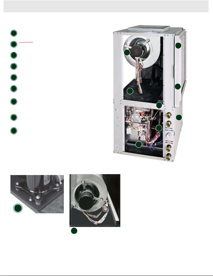
EF;B7D:W #?=> <X9?;D9O -9HEBB ECFH;IIEH EH |
|
Copeland UltraTech Two-Stage Scroll Compressor |
|
|
|
#?=> <X9?;D9O ,EJ7HO ECFH;IIEH |
|
|
|
|
2 |
)FJ?ED7B>ÌiÃÌÊ/iV-J7J; )<}Þ .>;iVÌÀ HJV>" ÞÊV ÕÌ>Ìi`]Ê |
x |
*À07H?78B;}À> -F;;:>Li]Ê6>ÀBEM;H>LiÊ'EJEH-«ii`Ê ÜiÀÊ Ì À |
||
3 |
E7J;: ?H E?B |
Ó |
|
||
iVÌÀ Ê`i« ÃÌ ÊV >Ìi`Ê>ÀÊV |
|
|
4 |
!KBBO $DIKB7J;: BEM;H -;9J?ED M?J> !KBBO |
|
$DIKB7J;: ECFH;IIEH -;9J?ED |
|
|
|
|
|
5 |
$DJ;=H7J;: !?BJ;H ,79A M?J> ,;JKHD ?H |
|
K9J EDD;9J?ED |
|
|
|
|
|
6 |
-BEF;:«i`Ê-Ì>H7?DiÃÃÊ*7D-M?J>ÌiiÊ À>ED:;DI7J;Ê*> ÊÜÌ Ê |
Î |
)L;HY`iEMÃ>ÌiÊ"ÛiÀy-;DIEH ÜÊ-i à À |
{ |
|
|
1 ÌÊ*iÀv À > ViÊ-i Ì i\Ê ÕÌ >ÌVÊ |
|
|
/D?J *;H<EHC7D9; -;DJ?D;B KJEC7J?9 |
|
7 |
iÀÌÊ-ÞÃÌi Ê iÌÃÊ i Ü iÀÊ ÜÊ vÊ |
|
B;HJ -OIJ;C &;JI 3EK %DEM $< .>; -OIJ;C |
È |
|
|
/ iÊ-ÞÃÌi Ê ÃÊ ÌÊ,Õ }Ê ÌÊ*i> Ê |
|
|
$I (EJ ,KDD?D= J *;7A *;H<EHC7D9; |
|
|
*iÀv À > ViI |
|
|
N9BKI?L; EK8B; -FH?D= D: "HECC;J |
|
8 |
ÕLiÊ-«À }Ê or`Ê À iÌÊ «ÀiÃÃ ÀÊ |
|
ECFH;IIEH $IEB7J?ED !EH /BJH7 |
||
|
à >Ì Ê ÀÊ1ÌÀ>Ê+ÕiÌÊ"«iÀ>Ì |
|
|
+K?;J )F;H7J?ED |
|
9 |
ÛiÊ >Ã ÞÊ,i Û>LiÊ-iÀÛViÊ VViÃÃÊ |
£ |
!?L; 7IO &?<J EKJ -;HL?9; 99;II *7D;BI |
|
|
|
*> ià |
|
Ç
8 |
I7 i Ê ÃÌ> i`ÊÜÌ Ê>ÊÌ iÀ ÃÌ>ÌÊÌ >ÌÊ >ÃÊ>Êv>ÕÌÊ |
Ó
4
Engineering Design Guide |
HTV/HTD/HTH SERIES |
Heat Controller, Inc. |
|
|
|
Heat ControllerTwoGeoMaxStage Geothermal2 n GeothermalHeat PumpHeatSystemsPump Systems
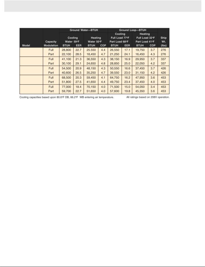
HT Series Ratings
ARI/ASHRAE/ISO 13256-1
at EWT (Entering Water Temperature)
HTV/HTD/HTH024
HTV/HTD/HTH036
HTV/HTD/HTH048
HTV/HTD/HTH060
HTV/HTD/HTH070
Heating capacities based upon 68°F DB, 59°F WB entering air temperature.
HT Electrical Data
|
Voltage |
|
Min/Max |
|
Compressor |
|
Fan Motor |
Total Unit |
|
|
||
Model |
Code |
Voltage |
Voltage |
QTY |
|
RLA |
|
LRA |
FLA |
FLA |
MCA |
Max/Fuse |
024 |
1 |
208/230-60/1 |
197/254 |
1 |
|
10.3 |
|
52.0 |
3.9 |
18.6 |
21.2 |
30 |
|
|
|
|
|
|
|
|
|
|
|
|
|
036 |
1 |
208/230-60/1 |
197/254 |
1 |
|
16.7 |
|
82.0 |
3.9 |
25.0 |
29.2 |
45 |
|
|
|
|
|
|
|
|
|
|
|
|
|
048 |
1 |
208/230-60/1 |
197/254 |
1 |
|
21.2 |
|
96.0 |
6.9 |
32.5 |
37.8 |
50 |
|
|
|
|
|
|
|
|
|
|
|
|
|
060 |
1 |
208/230-60/1 |
197/254 |
1 |
|
25.6 |
|
118.0 |
6.9 |
36.9 |
43.3 |
60 |
|
|
|
|
|
|
|
|
|
|
|
|
|
070 |
1 |
208/230-60/1 |
197/254 |
1 |
|
27.2 |
|
150.0 |
6.9 |
38.5 |
45.3 |
70 |
|
|
|
|
|
|
|
|
|
|
|
|
|
Min/Max Voltage of 197/254
HACR circuit breaker in USA only
All fuses Class RK-5
Wire size based on 60°C copper conductor and Minimum Circuit Ampacity.
Wire length based on one way measurement with 2% voltage drop
5
Heat Controller, Inc. |
HTV/HTD/HTH SERIES |
Engineering Design Guide |
|
|
|
Heat ControllerTwoGeoMaxStage Geothermal2 n GeothermalHeat PumpHeatSystemsPump Systems
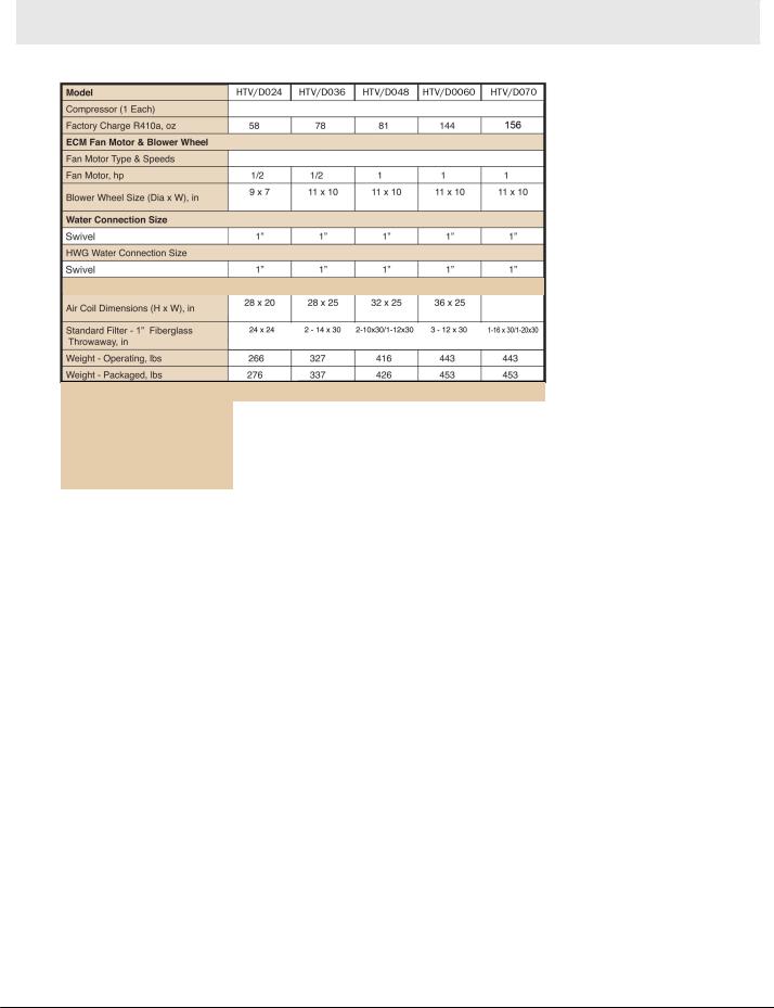
HT Physical Data
HT 024 |
|
HT 036 |
|
HT 048 |
|
HT 060 |
|
HT 070 |
Two-Stage Scroll
ECM Variable Speed
Vertical-HTV & Downflow-HTD
|
|
|
|
|
|
|
|
36x25 |
|
|
|
|
|
|
|
|
|
|
|
|
|
|
|
|
|
|
|
|
|
|
|
|
|
Standard Filter - 2” Pleated |
|
|
1(2)- 2414x-2428 |
1(2)- 2814x3030 |
1(2)- 301 x3032 |
1(1)- 3016x3036 |
1(1)- 3016x3036 |
|
|
|
HERV11, Quantity - in x in |
|
|
|
|
(1) 12x30 |
(1) 20x30 |
(1) 20x30 |
|
|
|
|
|
|
|
|
|
|
|
|
|
|
|
|
|
|
|
|
|
|
|
|
|
Horizontal-HTH |
|
|
|
|
|
|
|
|
|
|
Air Coil Dimensions (H x W), in |
|
18 x 31 |
20 x 35 |
20 x 40 |
20 x 45 |
20 x 45 |
|
||
|
|
|
|
|
|
|
|
|
|
|
|
Standard Filter - 2” Pleated |
|
2 - 18 x 18 |
1 - 12 x 20 |
1 - 18 x 20 |
2 - 20 x 24 |
2 - 20 x 24 |
|
||
|
MERV11, Quantity - in x in |
|
1 - 20 x 25 |
1 - 20 x 24 |
|
|||||
|
Weight - Operating, lbs |
|
266 |
327 |
416 |
443 |
443 |
|
|
|
|
|
|
|
|
|
|
|
|
|
|
|
Weight - Packaged, lbs |
|
276 |
337 |
426 |
453 |
453 |
|
|
|
All units have spring compressor mountings, TXV expansion devices, and 1/2” [12.7mm] & 3/4” [19.1mm] electrical knockouts.
6
Engineering Design Guide |
HTV/HTD/HTH SERIES |
Heat Controller, Inc. |
|
|
|
GeothermalTwo HeatStagePumpGeothermalSystemsHeatn PumpHeat SystemsController GeoMax 2
Dimensions – Vertical Upflow
Vertical |
|
Overall Cabinet |
|
|
|
|
|
|
|||||
|
|
|
|
|
|
|
|
|
|
|
|
||
Upflow |
|
A |
|
B |
|
|
C |
|
|
|
|
|
|
Model |
|
|
|
|
|
|
|
|
|
||||
|
Width |
|
Depth |
|
|
Height |
|
|
|
|
|
||
|
|
|
|
|
|
|
|
|
|
|
|||
|
|
|
|
|
|
|
|
|
|
|
|
|
|
0246 |
|
in |
22.4 |
25.6 |
|
|
48.5 |
|
|
|
|
|
|
|
cm |
56.8 |
65.1 |
|
|
123.2 |
|
|
|
|
|
||
|
|
|
|
|
|
|
|
|
|||||
|
|
|
|
|
|
|
|
|
|
|
|
|
|
0368 |
|
in |
25.4 |
30.6 |
|
|
50.5 |
|
|
|
|
|
|
|
cm |
64.5 |
77.8 |
|
|
128.3 |
|
|
|
|
|
||
|
|
|
|
|
|
|
|
|
|||||
|
|
|
|
|
|
|
|
|
|
|
|
|
|
0489 |
|
in |
25.4 |
30.6 |
|
|
54.5 |
|
|
|
|
|
|
|
cm |
64.5 |
77.8 |
|
|
138.4 |
|
|
|
|
|
||
|
|
|
|
|
|
|
|
|
|||||
|
|
|
|
|
|
|
|
|
|
|
|
|
|
0604 |
|
in |
25.4 |
30.6 |
|
|
58.5 |
|
|
|
|
|
|
|
cm |
64.5 |
77.8 |
|
|
148.6 |
|
|
|
|
|
||
|
|
|
|
|
|
|
|
|
|||||
|
|
|
|
|
|
|
|
|
|
|
|
|
|
0702 |
|
in |
25.4 |
30.6 |
|
|
58.5 |
|
|
|
|
|
|
|
cm |
64.5 |
77.8 |
|
|
148.6 |
|
|
|
|
|
||
|
|
|
|
|
|
|
|
|
|||||
|
|
|
|
|
|
|
|
|
|
|
|
|
|
|
|
|
|
|
|
|
|
Water Connections |
|
|
|||
|
|
|
|
|
|
|
|
|
|
|
|
|
|
Vertical |
|
1 |
2 |
|
|
3 |
4 |
5 |
|
|
|||
Upflow |
|
|
|
|
|
|
|
|
|
|
|
|
|
|
|
|
|
|
|
F |
|
G |
|
Loop |
|
||
Model |
|
D |
|
E |
|
|
|
H |
HWG |
||||
|
|
|
|
HWG |
|
HWG |
Water |
||||||
|
|
|
In |
|
Out |
|
|
|
Condensate |
IPT |
|||
|
|
|
|
|
|
IN |
|
Out |
IPT |
||||
|
|
|
|
|
|
|
|
|
|
|
|||
|
|
|
|
|
|
|
|
|
|
|
|
|
|
026024 |
|
in |
2.1 |
10.0 |
|
|
13.9 |
16.9 |
7.8 |
1” |
1” |
||
|
cm |
5.2 |
25.4 |
|
|
35.2 |
42.9 |
19.8 |
Swivel |
Swivel |
|||
|
|
|
|
|
|
|
|
|
|
|
|
|
|
038036 |
|
in |
3.4 |
10.8 |
|
|
15.6 |
18.9 |
7.8 |
1” |
1” |
||
|
cm |
8.6 |
27.5 |
|
|
39.7 |
47.9 |
19.8 |
Swivel |
Swivel |
|||
|
|
|
|
|
|
|
|
|
|
|
|
|
|
049048 |
|
in |
3.4 |
10.8 |
|
|
15.6 |
18.9 |
7.8 |
1” |
1” |
||
|
cm |
8.6 |
27.5 |
|
|
39.7 |
47.9 |
19.8 |
Swivel |
Swivel |
|||
|
|
|
|
|
|
|
|
|
|
|
|
|
|
060 |
|
in |
3.4 |
10.8 |
|
|
15.6 |
18.9 |
7.8 |
1” |
1” |
||
064 |
|
cm |
8.6 |
27.5 |
|
|
39.7 |
47.9 |
19.8 |
Swivel |
Swivel |
||
|
|
|
|
|
|
|
|
|
|
|
|
|
|
070 |
|
in |
3.4 |
10.8 |
|
|
15.6 |
18.9 |
7.8 |
1” |
1” |
||
072 |
|
cm |
8.6 |
27.5 |
|
|
39.7 |
47.9 |
19.7 |
Swivel |
Swivel |
||
|
|
|
|
|
|
|
|
|
|
|
|
|
|
|
|
|
|
|
|
|
|
|
|
|
|||
|
|
|
Electrical Knockouts |
|
|
|
|
|
|||||
|
|
|
|
|
|
|
|
|
|
|
|
|
|
Vertical |
|
J |
|
K |
|
L |
|
|
|
|
|
||
Upflow |
|
1/2” |
|
1/2” |
|
3/4” |
|
|
|
|
|
||
Model |
|
|
|
|
|
|
|
|
|
|
|
|
|
|
Low |
|
External |
|
Power |
|
|
|
|
|
|||
|
|
|
|
|
|
|
|
|
|
||||
|
|
|
Voltage |
|
Pump |
|
Supply |
|
|
|
|
|
|
|
|
|
|
|
|
|
|
|
|
|
|
|
|
0264 |
|
in |
3.6 |
|
6.1 |
|
|
8.6 |
|
|
|
|
|
|
cm |
9.2 |
|
15.6 |
|
|
21.9 |
|
|
|
|
|
|
|
|
|
|
|
|
|
|
|
|
||||
|
|
|
|
|
|
|
|
|
|
|
|
|
|
|
|
in |
3.6 |
|
6.1 |
|
|
8.6 |
|
|
|
|
|
0386 |
|
|
|
|
|
|
|
|
|
||||
|
cm |
9.2 |
|
15.6 |
|
|
21.9 |
|
|
|
|
|
|
|
|
|
|
|
|
|
|
|
|
||||
|
|
in |
3.6 |
|
6.1 |
|
|
8.6 |
|
|
|
|
|
0498 |
|
|
|
|
|
|
|
|
|
||||
|
cm |
9.2 |
|
15.6 |
|
|
21.9 |
|
|
|
|
|
|
|
|
|
|
|
|
|
|
|
|
||||
|
|
in |
3.6 |
|
6.1 |
|
|
8.6 |
|
|
|
|
|
0604 |
|
|
|
|
|
|
|
|
|
||||
|
cm |
9.2 |
|
15.6 |
|
|
21.9 |
|
|
|
|
|
|
|
|
|
|
|
|
|
|
|
|
||||
|
|
|
|
|
|
|
|
|
|
|
|
|
|
|
|
in |
3.6 |
|
6.1 |
|
|
8.6 |
|
|
|
|
|
0702 |
|
|
|
|
|
|
|
|
|
||||
|
cm |
9.2 |
|
15.6 |
|
|
21.9 |
|
|
|
|
|
|
|
|
|
|
|
|
|
|
|
|
||||
|
|
|
|
|
|
|
|
|
|
|
|
|
|
Condensate is 3/4” PVC female glue socket and is switchable from front to side.
Unit shipped with deluxe duct collar/filter rack extending from unit 3”2” [7(5.6c1 cm])and is suitableforductconnection. . Discharge flange is field installed.
7
Heat Controller, Inc. |
HTV/HTD/HTH SERIES |
Engineering Design Guide |
|
|
|
Heat ControllerTwoGeoMaxStage Geothermal2 n GeothermalHeat PumpHeatSystemsPump Systems
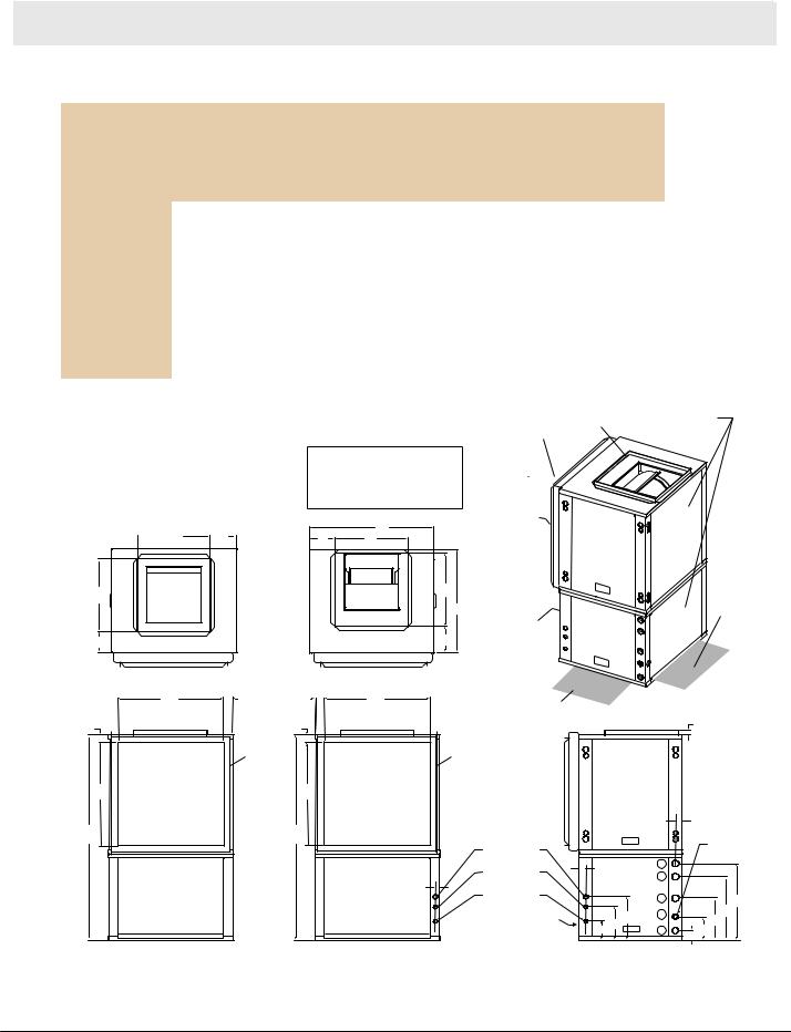
Dimensions – Vertical Upflow
|
|
|
|
|
Discharge Connection |
|
|
|
Return Connection |
|
||||
|
|
|
|
|
|
|
Standard Deluxe Filter Rack |
|
||||||
Vertical |
|
Duct Flange Installed (+/- 0.10 in, +/- 2.5mm) |
|
|
||||||||||
|
|
(+/- 0.10 in, +/- 2.5mm) |
|
|||||||||||
|
|
|
|
|
|
|
|
|||||||
Upflow |
|
|
|
|
|
|
|
|
|
|
|
|
||
|
M |
|
O |
P |
Q |
|
|
S |
T |
|
|
|||
Model |
|
|
|
|
|
|
||||||||
|
|
|
|
Left |
N |
Supply |
Supply |
Right |
R |
|
Return |
Return |
|
U |
|
|
|
|
Return |
|
Width |
Depth |
Retuen |
|
|
Depth |
Height |
|
|
|
|
|
|
|
|
|
|
|
|
|
|
|
|
|
0246 |
|
|
in |
7.8 |
5.8 |
14.0 |
14.0 |
4.9 |
1.7 |
|
22.2 |
26.2 |
|
1.5 |
|
|
cm |
18.3 |
14.8 |
35.6 |
35.6 |
12.4 |
4.2 |
|
56.4 |
66.4 |
|
3.9 |
|
|
|
|
|
|
||||||||||
|
|
|
in |
6.4 |
6.3 |
18.0 |
18.0 |
5.3 |
2.1 |
|
27.1 |
26.1 |
|
1.5 |
0368 |
|
|
|
|
||||||||||
|
|
cm |
16.1 |
16.0 |
45.7 |
45.7 |
13.5 |
5.4 |
|
68.9 |
66.4 |
|
3.9 |
|
|
|
|
|
|
||||||||||
|
|
|
in |
6.4 |
6.3 |
18.0 |
18.0 |
5.3 |
2.1 |
|
27.1 |
30.1 |
|
1.5 |
0489 |
|
|
|
|
||||||||||
|
|
cm |
16.1 |
16.0 |
45.7 |
45.7 |
13.5 |
5.4 |
|
68.9 |
76.5 |
|
3.9 |
|
|
|
|
|
|
||||||||||
0604 |
|
|
in |
6.4 |
6.3 |
18.0 |
18.0 |
5.3 |
2.1 |
|
27.1 |
34.1 |
|
1.5 |
|
|
cm |
16.1 |
16.0 |
45.7 |
45.7 |
13.5 |
5.4 |
|
68.9 |
86.7 |
|
3.9 |
|
|
|
|
|
|
||||||||||
0702 |
|
|
in |
6.4 |
6.3 |
18.0 |
18.0 |
5.3 |
2.1 |
|
27.1 |
34.1 |
|
1.5 |
|
|
cm |
16.1 |
16.0 |
45.7 |
45.7 |
13.5 |
5.4 |
|
68.9 |
86.7 |
|
3.9 |
|
|
|
|
|
|
||||||||||
|
|
|
|
|
|
|
|
|
|
|
|
|
|
|
 P
P 
 N
N 
O |
Front |
|
|
Q |
Air Coil Side |
Top View-Right Return
|
|
|
|
Field Installed |
Access Panels |
|
|
|
|
|
Discharge Flange |
|
|
|
|
|
|
|
|
|
|
|
|
Deluxe Filter Bracket |
|
|
|
|
Legend |
|
|
|
|
|
CAP=Control Access Panel |
|
|
|
|
|
|
CSP=Compressor Service Panel |
|
|
|
|
||
BSP=Blower Service Panel |
|
|
|
|
|
|
ASP=Alternate Service Panel |
|
|
|
|
||
|
B |
|
Air Coil |
|
|
|
|
|
|
|
ASP |
|
|
N |
P |
|
|
|
|
|
|
|
BSP |
|
|
||
|
|
|
|
|
|
|
|
Front |
O |
|
|
|
2' (61cm) |
|
A |
|
|
|
Optional |
|
|
|
|
|
|
Service |
|
|
|
|
|
|
|
Access |
|
|
|
CSP |
|
ASP |
Left Rtn |
|
|
M |
CAP |
|
(right |
|
|
Air Coil Side |
|
|
Opposite) |
||
|
|
|
|
|
||
Top View-Left Return
|
S |
R |
R |
S |
|
2' (61cm) |
|
Isometric |
|
|
|
|
|
|
|
|
|
|
|
|
|
|
|||
U |
|
|
U |
|
|
Service |
|
View |
|
1.00 [25.4 mm] |
||
|
|
|
|
|
|
|
|
|||||
|
|
Air Coil |
|
|
Air Coil |
|
|
|
|
|
|
|
T |
Residential |
|
T |
Residential |
|
|
|
|
|
|
|
|
Filter Rack |
|
Filter Rack |
|
|
|
|
|
|
|
|
||
|
Shown |
|
|
Shown |
|
|
|
|
|
|
|
|
|
|
|
|
|
|
|
|
|
|
1.68 [42.7 mm] |
||
C |
|
|
C |
|
Power Supply |
|
|
|
|
|
|
Condensate |
|
|
|
|
|
|
|
|
|
|
|
||
|
|
|
|
|
3 / 4" [19.1mm] |
|
|
|
|
|
|
3 / 4" Glue |
|
|
|
|
|
HV Knockout |
|
|
|
4 |
|
|
(PVC Socket) |
|
|
|
|
|
1 / 2" [12.7mm] |
1.63 |
|
CAP |
|
|
|
|
|
|
|
|
|
|
|
|
|
|
|||
|
|
|
|
|
Knockout |
[41.4 mm] |
|
3 |
|
|
|
|
|
|
|
|
|
|
|
|
|
|
|
||
|
|
|
|
1.18 [30.0 mm] |
Low Voltage |
|
|
|
|
|
|
|
|
ASP |
|
|
CSP |
1 / 2" [12.7mm] |
|
|
|
2 |
|
|
F G |
|
|
|
LV Knockout |
|
|
|
|
|
||||
|
|
|
|
|
|
|
|
|
|
|
||
|
|
|
|
|
|
|
|
|
|
|
|
|
Front |
|
Back |
Back |
|
Front |
CSP |
K |
L |
5 |
|
H |
E |
|
|
J |
|
1 |
D |
|||||||
|
|
|
|
|
|
|
||||||
|
Right Return Right View |
|
|
Left Return Left View |
|
|
Front-View |
|
|
|
||
|
|
|
|
|
|
|
|
|
||||
|
- Filter Rack Knife Edge |
|
|
- Filter Rack Knife Edge |
|
|
|
|
|
|
|
|
8
 Loading...