


Heat Controller B-VMH09FC-1, B-VCH18FC-1, B-VMH18FC-1, A-VCH27TC-1, B-VMH12FC-1 User Manual
...INSTALLATION
MANUAL
Indoor Models:
B-VCH12FC-1
B-VCH18FC-1
B-VMH09FC-1
B-VMH12FC-1
B-VMH18FC-1
Version C
InverterFlex
Ductless Mini-Split Heat Pumps
High Wall and Ceiling Cassettes
Outdoor Models:
A-VCH18DC-1
A-VCH27TC-1
A-VMH36QC-1
Heat Controller, Inc. • 1900 Wellworth Ave. • Jackson, MI 49203 • (517)787-2100 • www.heatcontroller.com

Installation Manual |
VMH Series |
Heat Controller, Inc. |
|
|
|
|
CONTENTS |
SAFETY PRECAUTIONS |
|
Warning ........................................................................................................................................... |
2 |
Caution ............................................................................................................................................ |
2 |
Nomenclature Combinations............................................................... |
..............................................4 |
INSTALLATION INSTRUCTIONS |
|
Selecting installation place............................................................................................................... |
3 |
Wall-mounted type ........................................................................................................................... |
3 |
Accessories ....................................... |
..................................................................4 |
Four-way cassette type ................................................................................................................ |
9 |
Duct & Ceiling type ....................................................................................................................... |
12 |
Outdoor unit installation ........................................ |
........................................................................23 |
REFRIGERANT PIPE CONNECTION |
|
Refrigerant pipe connection .......................................................................................................... |
24 |
ELECTRICAL WORK |
|
Electrical work .................. ........................................................................................................... |
25 |
AIR PURGING |
|
Air purging with vacuum pump ..................................................................................................... |
27 |
Safety and leakage check ............................................................................................................ |
29 |
TEST RUNNING |
|
Test running .................................................................................................................................. |
30 |
Read This Manual
Inside you will find many helpful hints on how to install and test the air conditioner properly.
All the illustrations and specifications in the manual are subject to change without prior notice for product improvement. The actual shape should prevail.
 CAUTION
 Contact an authorised service technician for repair or maintenance of this unit.
 Contact an authorised installer for installation of this unit.
 The air conditioner is not intended for use by young children or infirmed persons without supervision.
 Young children should be supervised to ensure that they do not play with the air conditioner.
 If the power cord is to be replaced, replacement work shall be performed by authorised personnel only.
  Installation work must be performed in accordance with the national wiring Standards by authorised personnel only.
2
Heat Controller, Inc. |
VMH Series |
Installation Manual |
|
|
|
SAFETY PRECAUTIONS
 Read the follow SAFETY PRECAUTIONS carefully before installation.
 Electrical work must be installed by a licensed electrician. Be sure to use the correct rating of the power plug and main circuit for the model to be installed.
 Incorrect installation due to ignoring of the instruction will cause harm or damage.
 The seriousness is classified by the following indications.
WARNING |
This symbol indicates the possibility of death or serious injury. |
|
|
CAUTION |
This symbol indicates the possibility of injury or damage to property. |
|
|
 The items to be followed are classified by the symbols:
Symbol with background white denotes item that is PROHIBITED from doing.
 WARNING
1)Engage dealer or specialist for installation. If installation done by the user is defective, it will cause water leakage, electrical shock fire.
2)Install according to this installation instructions strictly. If installation is defective, it will cause water leakage, electrical shock fire.
3)Use the attached accessories parts and specified parts for installation. otherwise, it will cause the set to fall, water leakage, electrical shock fire.
4)Install at a strong and firm location which is able to withstand the set,s weight. If the strength is not enough or installation is not properly done, the set will drop and cause injury.
5)For electrical work, follow the local national wiring standard, regulation and this installation instructions. An independent circuit and single outlet must be used. If electrical circuit capacity is not enough or defect found in electrical work, it will cause electrical shock fire.
6)Use the specified cable and connect tightly and clamp the cable so that no external force will be acted on the terminal. If connection or fixing is not perfect, it will cause heat-up or fire at the connection.
7)Wiring routing must be properly arranged so that control board cover is fixed properly. If control board cover is not fixed perfectly, it will cause heat-up at connection point of terminal, fire or electrical shock.
8)When carrying out piping connection, take care not to let air substances other than the specified
refrigerant go into refrigeration cycle. Otherwise, it will cause lower capacity, abnormal high pressure in the refrigeration cycle, explosion and injury.
9)Do not modify the length of the power supply cord or use of extension cord, and do not share the single outlet with other electrical appliances. Otherwise, it will cause fire or electrical shock.
 CAUTION
1)This equipment must be earthed and installed with earth leakage current breaker. It may cause electrical shock if grounding is not perfect.
2)Do not install the unit at place where leakage of flammable gas may occur. In case gas leaks and accumulates at surrounding of the unit, it may cause fire.
3)Carry out drainage piping as mentioned in installation instructions. If drainage is not perfect, water
may enter the room and damage the furniture.
3
Installation Manual |
VMH Series |
Heat Controller, Inc. |
|
|
|
Nomenclature
Outdoor Models:
A - vmh18dc - 1
Outdoor Inverter |
Heat |
Multi-Zone |
Nominal Capacity |
D=Dual Zone |
|
Pump |
Mini-Split |
18=18kBtu/H |
T-Tri-Zone |
|
|
|
27=27kBtu/H |
Q-Quad Zone |
|
|
|
36=36kBtu/H |
|
Indoor Models:
B - vmh09Fc - 1
|
|
|
|
|
|
|
|
|
|
|
|
|
|
|
|
|
|
|
|
|
|
|
|
|
|
|
|
|
|
|
|
|
|
|
|
|
|
|
|
|
|
|
|
|
|
|
|
|
|
|
|
|
|
|
|
|
|
|
|
|
|
|
|
|
|
|
|
|
|
|
|
|
|
|
|
|
|
|
|
Indoor Inverter M=Mini-Split |
Heat |
Capacity |
|
|
Voltage Code |
||||||||||
|
|
high wall |
Pump |
09=09kBtu/H* |
|
|
1=208/230V-60hz-1PH |
||||||||
|
|
mount |
|
|
12=12kBtu/H |
|
|
|
|
||||||
|
|
|
|
|
|
||||||||||
|
|
C=Ceiling |
|
|
18=18kBtu/H Design |
Flexible |
|||||||||
|
|
cassette |
|
|
*not available in |
Series |
Matching |
||||||||
|
|
|
|
ceiling cassette |
|||||||||||
|
|
|
|
|
|
|
|
|
capabilities |
||||||
|
|
|
|
|
|
|
|
|
|
|
|
|
|
||
4

Heat Controller, Inc. |
VMH Series |
Installation Manual |
|
|
|
Unit combinations
NOTE: The total capacity of indoor air handlers can not exceed the nominal capacity of the outdoor unit. The minimum quantity of indoor air handlers is one on any outdoor unit, whether it is a dual, tri, or quad zone.
Indoor unit combinations for A-VMH18DC-1
Comb. |
Combinations |
||
Unit A |
Unit B |
||
|
|||
Dual(1x1) |
9k |
— |
|
12k |
— |
||
|
18k |
— |
|
Dual (1x2) |
9k |
9k |
|
9k |
12k |
||
|
|||
Indoor unit combinations for A-VMH27TC-1
Comb. |
Combinations |
|||
Unit A |
Unit B |
Unit C |
||
|
||||
TRI (1x1) |
9k |
— |
— |
|
12k |
— |
— |
||
|
18k |
— |
— |
|
|
9k |
9k |
— |
|
TRI (1x2) |
9k |
12k |
— |
|
9k |
18k |
— |
||
|
||||
|
12k |
12k |
— |
|
TRI (1x3) |
9k |
9k |
9k |
|
Indoor unit combinations for A-VMH36QC-1
Comb. |
|
Combinations |
|
||
Unit A |
Unit B |
Unit C |
Unit D |
||
|
|||||
QUA (1x1) |
9k |
— |
— |
— |
|
12k |
— |
— |
— |
||
|
18k |
— |
— |
— |
|
|
9k |
9k |
— |
— |
|
|
9k |
12k |
— |
— |
|
QUA (1x2) |
9k |
18k |
— |
— |
|
12k |
12k |
— |
— |
||
|
|||||
|
12k |
18k |
— |
— |
|
|
18k |
18k |
— |
— |
|
|
9k |
9k |
9k |
— |
|
QUA (1x3) |
9k |
9k |
12k |
— |
|
9k |
9k |
18k |
— |
||
|
9k |
12k |
12k |
— |
|
|
12k |
12k |
12k |
— |
|
QUA(1x4) |
9k |
9k |
9k |
9k |
|
Available indoor models:
|
High Wall Mount |
Ceiling Cassette |
9k |
B-VMH09FC-1 |
N/A |
12k |
B-VMH12FC-1 |
B-VCH12FC-1 |
18k |
B-VMH18FC-1 |
B-VCH18FC-1 |
5

Installation Manual |
VMH Series |
Heat Controller, Inc. |
|
|
|
INSTALLATION INSTRUCTIONS
NOTE: Indoor units shown can be replaced with ceiling cassettes.
|
|
|
Mo |
|
|
|
2 |
More than 15cm |
|
|
|
|
|
|
|
1 |
|
|
|
|
ret |
han |
|
|
|
|
|
|
|
|
12cm |
|
|
|
3 |
|
|
|
|
|
|
|
|
|
|
|
|
|
|
|
|
ter |
|
|
|
|
r |
|
filter |
|
Airfil |
|
|
|
|
|
|
|
|
||
|
|
te |
Air |
|
|
|
||
Air |
fil |
|
|
|
|
ter |
||
|
|
|
|
|
|
|
||
|
|
|
|
|
|
|
Airfil |
|
|
|
|
|
|
|
5 |
Remote |
4 |
|
|
|
|
Remote |
|
|||
Remote |
|
controller |
|
|||||
controller |
|
|
||||||
controller |
|
|
|
|||||
|
|
|
|
|
||||
|
|
|
|
|
|
|
Remote |
|
|
|
|
|
|
|
|
controller |
|
|
|
|
|
|
|
|
|
6 |
|
|
|
|
|
|
|
Air out |
|
|
|
|
er |
|
|
|
|
|
Air |
filt |
|
|
|
|
|
||
|
|
|
|
|
|
|
||
|
|
|
|
|
One-Two |
|
Loop a |
|
|
|
|
|
|
|
connective |
|
|
|
|
|
|
|
One-Three |
|
cable |
|
|
|
|
|
|
|
|
|
|
Remote |
|
One-Four |
|
|
|
|||
controller |
|
One-Five |
|
|
|
|||
|
|
|
|
|
|
|
|
|
|
|
|
|
|
|
|
CAUTIONS |
|
 This illustration is for explanation purposes only. The actual shape of your air condtioner may be slightly different.
 Copper lines must be insulated independently
CAUTION
NOTE: Ceiling cassettes come with an optional wall mounted wireless thermostat that can take the place of the wireless remote controller.
6
Heat Controller, Inc. |
VMH Series |
Installation Manual |
|
|
|
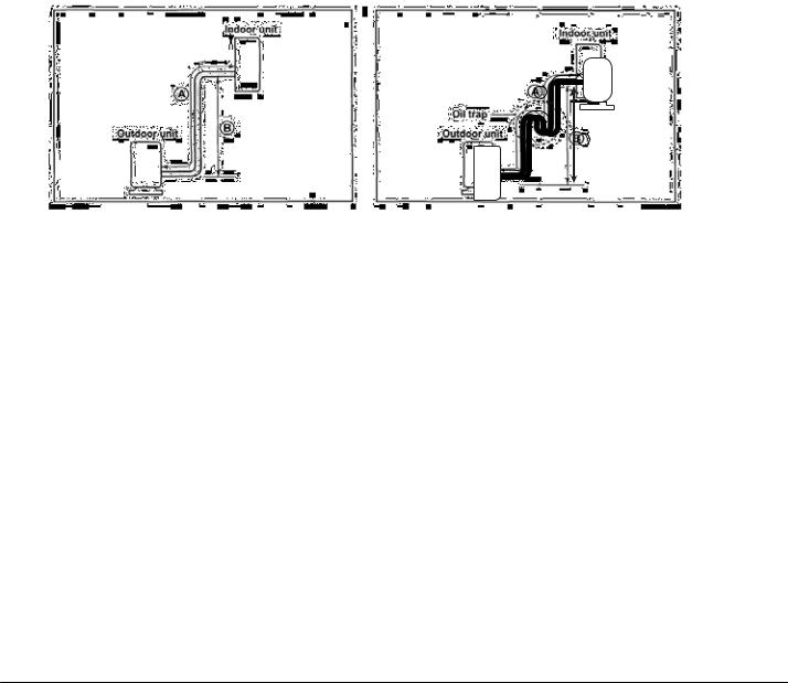
Pipe length and elevation
|
Pipe size |
Standard |
|
|
Max. |
|
Max. |
|
Additional |
|||||||||
Unit |
|
|
|
length |
|
Elevation |
|
Length |
|
refrigerant |
||||||||
Gas inch |
Liquid inch |
|||||||||||||||||
|
(mm) |
(mm) |
|
|
(m) |
|
B (m) |
|
A (m) |
|
(g/m) |
|||||||
|
|
|
|
|
|
|
|
|
|
|
|
|
|
|
|
|
|
|
9K |
3/8’’ (Ф9.52) |
1/4’’ (Ф6.35) |
(5) |
|
(10) |
|
|
(15) |
|
|
(20) |
|
||||||
|
|
|
|
|
16.5ft |
|
|
33ft |
|
50ft |
|
0.2 oz/ft |
||||||
12K/18K |
1/2’’ (Ф12.7) |
1/4’’ (Ф6.35) |
|
|
|
|
|
|
||||||||||
|
|
|
|
|
|
|
|
|
|
|
|
|
|
|
|
|
|
|
Max. Total length for all rooms |
Dual-zone(m) |
|
|
Tri-zone(m) |
|
Quad-zone(m) |
||||||||||||
|
|
|
|
|
|
|
|
|
|
|
|
|
|
|
|
|||
|
|
|
|
|
(30)100ft |
|
|
(45)150ft |
|
|
(60)200ft |
|||||||
|
|
|
|
|
|
|
|
|
|
|
|
|
|
|
|
|
|
|
|
|
|
|
|
|
|
|
|
|
|
|
|
|
|
||||
|
|
|
|
|
|
|
|
|
|
|
|
|
|
|
||||
|
|
|
|
|
|
|
|
|
|
|
|
2XWGRRU XQLW |
|
|
||||
|
|
|
|
|
|
|
|
|
|
|
$ |
|
|
|
|
|
|
|
|
|
|
|
|
|
2LO WUDS |
|
|
|
|
|
|
|
|
|
|
||
|
|
|
|
|
|
|
|
|
|
|
|
|
|
|
||||
|
|
|
|
|
,QGRRU XQLW |
% |
|
|
|
|
|
|
||||||
|
|
|
|
|
|
|
|
|
|
|
|
|
|
|
|
|
||
|
|
|
|
|
|
|
|
|
|
|
|
|
|
|
|
|
|
|
|
|
|
|
|
|
|
|
|
|
|
|
|
|
|
|
|
|
|
|
|
|
|
|
|
|
|
|
|
|
|
|
|
|
|
|
|
|
NOTES:
•Do not exceed 50 ft. (15m) per each indoor unit.
•Minimum pipe lenght of 10ft (3m) is required for each indoor unit.
•Oil trap should be installed per (3-5 meters) 10-15 ft., where outdoor unit is located above indoor unit.
•Outdoor connections are 1/4” (f6.35 mm) liquid and 3/8” (f9.52 mm) gas, therefore a flare nut adapter is provided with all 12/18k indoor sections.
7
Installation Manual |
VMH Series |
Heat Controller, Inc. |
|
|
|
INSTALLATION INSTRUCTIONS
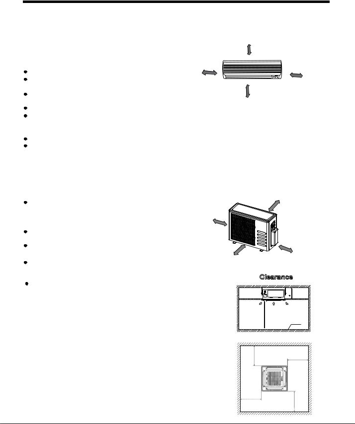
1. Selecting Installation Place
Read completely, then follow step by step.
More than 6in.(15cm)
Indoor unit
More than 5in.(12cm)
More than 5in.(12cm)
Do not expose the indoor unit to heat or steam. |
|
|
Select a place where there are no obstacles |
|
|
in front or around the unit. |
|
|
Make sure that condensation drainage can |
More than 6.5 ft.(2.0m) |
|
|
||
be conveniently routed away. |
Fig.1 |
|
Do not install near a doorway. |
||
|
||
Ensure that the proper clearance is maintained per Fig.1. |
|
Use a stud finder to locate studs to prevent unnecessary damage to the wall.  Variations in pipe length may require adjustment to refrigerant charge.
There should not be any direct sunlight. Otherwise, the sun will fade the plastic cabinet and affect its appearance. If unavoidable, sunlight prevention should be taken into consideration.
Outdoor unit
If an awning is built over the outdoor unit to |
|
More than 1ft.(30cm) |
|
|
|
|
|
prevent direct sunlight or rain exposure, |
More than 1 ft.(30cm) |
|
|
make sure that heat radiation from the |
|
|
|
condenser is not restricted. |
|
|
|
Ensure that the clearance is maintained |
|
|
|
per Fig 2. |
|
|
More than 2ft.(60cm) |
Do not place animals and plants in the path |
|
|
|
of the air inlet or outlet. |
More than 6.5 ft.(200cm) |
|
|
Take the air conditioner weight into account |
|
|
|
|
Fig.2 |
|
|
and select a place where noise and vibration |
|
|
|
will not be an issue. |
Clearance |
||
Select a place so that the warm air and noise from |
|
11” (280mm) |
|
the air conditioner do not disturb neighbors. |
|
|
|
|
|
|
A |
|
Outlet |
Inlet |
Outlet |
|
7.5ft (>2300) |
|
Ground |
|
|
Fig.13 |
|
|
(>1000) |
|
3.5ft (>1000) |
|
3.5ft |
|
|
|
|
|
|
|
3.5ft (>1000) |
|
5.3 |
|
|
|
(>1000) ft |
|
|
Fig.14 |
|
|
8 |
|
|
 Loading...