


Owner’s Manual
Installation and Operation
Models:
ST-36TR-IPI
ST-36TRLP-IPI
PIER-36TR-IPI
PIER-36TRLP-IPI
NOTICE
DO NOT DISCARD THIS MANUAL
• Important operating |
• Read, understand and follow |
• Leave this manual |
and maintenance |
these instructions for safe |
party responsible for |
instructions included. |
installation and operation. |
and operation. |
DO DISCARDNOT
 WARNING: If the information in these instructions is not followed exactly, a fire or explosion may result causing property damage, personal injury, or death.
•DO NOT store or use gasoline or other flammable vapors and liquids in the vicinity of this or any other appliance.
•What to do if you smell gas
-DO NOT try to light any appliance.
-DO NOT touch any electrical switch. DO NOT use any phone in your building.
-Immediately call your gas supplier from a neighbor’s phone. Follow the gas supplier’s instructions.
-If you cannot reach your gas supplier, call the fire department.
•Installation and service must be performed by a qualified installer, service agency, or the gas supplier.
This appliance may be installed as an OEM installation in manufactured home (USA only) or mobile home and must be installed in accordance with the manufacturer’s instructions and the manufactured home construction and safety standard,
Title 24 CFR, Part 3280 or Standard for Installation in Mobile Homes, CAN/CSA Z240MH, in Canada.
This appliance is only for use with the type(s) of gas indicated on the rating plate.
 WARNING
HOT SURFACES!
Glass and other surfaces are hot during operation AND cool down.
Hot glass will cause burns.
• DO NOT touch glass until it is cooled
•NEVER allow children to touch glass
•Keep children away
•CAREFULLY SUPERVISE children in same room as fireplace.
•Alert children and adults to hazards of high temperatures.
High temperatures may ignite clothing or other flammable materials.
•Keep clothing, furniture, draperies and other flammable materials away.
This appliance has been supplied with an integral barrier to prevent direct contact with the fixed glass panel. DO NOT operate the appliance with the barrier removed.
Contact your dealer or Hearth & Home Technologies if the barrier is not present or help is needed to properly install one.
In the Commonwealth of Massachusetts installation must be performed by a licensed plumber or gas fitter.
See Table of Contents for location of additional Commonwealth of Massachusetts requirements.
Installation and service of this appliance should be performed by qualified personnel. Hearth & Home Technologies suggests NFI certified or factory trained professionals, or technicians supervised by an NFI certified professional.
Heat & Glo • ST-36TR-IPI, PIER-36TR-IPI • 2176-900 Rev. F • 8/11 |
1 |
Read this manual before installing or operating this appliance.
Please retain this owner’s manual for future reference.
A. Congratulations
Congratulations on selecting a Heat & Glo gas fireplace, an elegant and clean alternative to wood burning fireplaces. The Heat & Glo gas fireplace you have selected is designed to provide the utmost in safety, reliability, and efficiency.
As the owner of a new fireplace, you’ll want to read and carefully follow all of the instructions contained in this owner’s manual. Pay special attention to all cautions and warnings.
This owner’s manual should be retained for future reference. We suggest that you keep it with your other important documents and product manuals.
The information contained in this owner’s manual, unless noted otherwise, applies to all models and gas control systems.
Your new Heat & Glo gas fireplace will give you years of durable use and trouble-free enjoyment. Welcome to the Heat & Glo family of fireplace products!
Homeowner Reference Information
We recommend that you record the following pertinent information about your fireplace.
Model Name: ___________________________________________ Date purchased/installed:__________________
Serial Number:__________________________________________ Location on fireplace: _____________________
Dealership purchased from: _______________________________ Dealer Phone: __________________________
Notes: _______________________________________________________________________________________
_____________________________________________________________________________________________
Listing Label Information/Location The model information regarding your specific fireplace can be found on the rating plate usually located in the control area of the fireplace.
Type of Gas
Gas and Electric
Information
Heat & Glo, a brand of Hearth & Home Technologies, Inc. 7571 215th Street West, Lakeville, MN 55044
Not for use with solid fuel.
(Ne doit pas entre utilise avec un combustible solide).
Type of Gas (Sorte De Gaz): This appliance must be installed in accordance with local codes, if any; if not, follow ANSI Z223.1 in the USA or CAN/CGA B149 installation codes. (Installer l’appareil selon les codes ou reglements locaux ou, en l’absence de tels reglements, selon les codes d’installation CAN/CGA-B149.)
ANSI Z21XX-XXXX · CSA 2.XX-MXX · UL307B
Minimum Permissible Gas Supply for Purposes of Input Adjustment. |
|
|
|
||||||
Approved Minimum (De Gaz) Acceptable |
0.0 in w.c. |
(Po. Col. d’eau) |
|
|
|
||||
Maximum Pressure (Pression) |
|
0.0 in w.c. |
(Po. Col. d’eau) |
|
|
|
|||
Maximum Manifold Pressure (Pression) |
0.0 in w.c. |
(Po. Col. d’eau) |
|
|
|
||||
Minimum Manifold Pressure (Pression) |
0.0 in w.c. |
(Po. Col. d’eau) |
|
|
|
||||
Total Electrical Requirements: 000Vac, 00Hz., less than 00 Amperes |
MADE IN USA |
|
|
||||||
|
|
|
|
|
|
|
|
|
|
|
|
IN CANADA |
|
Model: |
XXXXXXXX |
|
|||
ALTITUDE: |
0-0000 FT. |
0000-0000FT. |
|
||||||
(Modele): |
|
||||||||
MAX. INPUT BTUH: |
00,000 |
00,000 |
|
|
|
|
|
|
|
MIN. INPUT BTUH: |
00,000 |
00,000 |
|
Serial |
XXXXXXXX |
|
|||
ORIFICE SIZE: |
#XXXXX |
#XXXXX |
|
|
|||||
|
(Serie): |
|
|||||||
Model Number
Serial Number
2 |
Heat & Glo • ST-36TR-IPI, PIER-36TR-IPI • 2176-900 Rev. F • 8/11 |
 Safety Alert Key:
•DANGER! Indicates a hazardous situation which, if not avoided will result in death or serious injury.
•WARNING! Indicates a hazardous situation which, if not avoided could result in death or serious injury.
•CAUTION! Indicates a hazardous situation which, if not avoided, could result in minor or moderate injury.
•NOTICE: Used to address practices not related to personal injury.
Table of Contents
A. Congratulations . . . . . . . . . . . . . . . . . . . . . . . . . . . . . . . . . 2
B. Limited Lifetime Warranty. . . . . . . . . . . . . . . . . . . . . . . . . . 5
1 Listing and Code Approvals
A. Appliance Certification . . . . . . . . . . . . . . . . . . . . . . . . . . . . 7 B. Tempered Glass Specifications . . . . . . . . . . . . . . . . . . . . . 7 C. BTU Specifications. . . . . . . . . . . . . . . . . . . . . . . . . . . . . . . 7 D. High Altitude Installations . . . . . . . . . . . . . . . . . . . . . . . . . . 7 E. Non-Combustible Materials Specification. . . . . . . . . . . . . . 7 F. Combustible Materials Specification . . . . . . . . . . . . . . . . . 7 G. Electrical Codes . . . . . . . . . . . . . . . . . . . . . . . . . . . . . . . . . 7 H. Requirements for the Commonwealth of Massachusetts. . 8
User Guide
2 Operating Instructions
A. Gas Fireplace Safety . . . . . . . . . . . . . . . . . . . . . . . . . . . . . 9 B. Your Fireplace . . . . . . . . . . . . . . . . . . . . . . . . . . . . . . . . . . 9 C. Blower Kit (optional) . . . . . . . . . . . . . . . . . . . . . . . . . . . . . 10 D. Clear Space . . . . . . . . . . . . . . . . . . . . . . . . . . . . . . . . . . . 10 E. Decorative Doors and Fronts . . . . . . . . . . . . . . . . . . . . . . 10 F. Fixed Glass Assembly . . . . . . . . . . . . . . . . . . . . . . . . . . . 10 G. Remote Controls, Wall Controls and Wall Switches. . . . . 10 H. Before Lighting Fireplace . . . . . . . . . . . . . . . . . . . . . . . . . 10 I. Lighting Instructions (IPI) . . . . . . . . . . . . . . . . . . . . . . . . . 11 J. After Fireplace is Lit . . . . . . . . . . . . . . . . . . . . . . . . . . . . . 12 K. Frequently Asked Questions . . . . . . . . . . . . . . . . . . . . . . 12
3 Maintenance and Service
A. Maintenance Tasks-Homeowner . . . . . . . . . . . . . . . . . . . 13
B. Maintenance Tasks-Qualified Service Technician . . . . . . 14
7 Vent Information and Diagrams
A. Approved Pipe . . . . . . . . . . . . . . . . . . . . . . . . . . . . . . . . . 26
B. Vent Table Key . . . . . . . . . . . . . . . . . . . . . . . . . . . . . . . . . 26
C. Use of Elbows . . . . . . . . . . . . . . . . . . . . . . . . . . . . . . . . . 26
D. Measuring Standards . . . . . . . . . . . . . . . . . . . . . . . . . . . . 26
E. Vent Diagrams . . . . . . . . . . . . . . . . . . . . . . . . . . . . . . . . . 27
8 Vent Clearances and Framing
A. Pipe Clearances to Combustibles . . . . . . . . . . . . . . . . . . 37 B. Wall Penetration Framing. . . . . . . . . . . . . . . . . . . . . . . . . 37 C. Vertical Penetration Framing . . . . . . . . . . . . . . . . . . . . . . 38 D. Install Attic Insulation Shield. . . . . . . . . . . . . . . . . . . . . . . 39
9 Appliance Preparation
A. Top Vent . . . . . . . . . . . . . . . . . . . . . . . . . . . . . . . . . . . . . . 40
B. Rear Vent . . . . . . . . . . . . . . . . . . . . . . . . . . . . . . . . . . . . . 41
C. Securing and Leveling the Appliance . . . . . . . . . . . . . . . . 42
10 Installing Vent Pipe (DVP and SLP Pipe)
A. Assemble Vent Sections (DVP Pipe Only) . . . . . . . . . . . . 43 B. Assemble Vent Sections (SLP Pipe Only) . . . . . . . . . . . . 44 C. Assemble Slip Sections . . . . . . . . . . . . . . . . . . . . . . . . . . 44 D. Secure the Vent Sections. . . . . . . . . . . . . . . . . . . . . . . . . 45 E. Disassemble Vent Sections . . . . . . . . . . . . . . . . . . . . . . . 45 F. Install Decorative Ceiling Components (SLP only). . . . . . 46 G. Install Metal Roof Flashing. . . . . . . . . . . . . . . . . . . . . . . . 47 H. Assemble and Install Storm Collar . . . . . . . . . . . . . . . . . . 47 I. Install Vertical Termination Cap . . . . . . . . . . . . . . . . . . . . 48 J. Install Decorative Wall Components (SLP only). . . . . . . . 48 K. Heat Shield Requirements for Horizontal Termination . . . 48 L. Install Horizontal Termination Cap (DVP and SLP Pipe) . 49
Installer Guide
4 Getting Started
A. Typical Appliance System. . . . . . . . . . . . . . . . . . . . . . . . . 16
B. Design and Installation Considerations . . . . . . . . . . . . . . 17
C. Tools and Supplies Needed . . . . . . . . . . . . . . . . . . . . . . . 17
D. Inspect Appliance and Components. . . . . . . . . . . . . . . . . 17
5 Framing and Clearances
A. Selecting Appliance Location . . . . . . . . . . . . . . . . . . . . . . 18
B. Constructing the Appliance Chase . . . . . . . . . . . . . . . . . . 19
C. Clearances . . . . . . . . . . . . . . . . . . . . . . . . . . . . . . . . . . . . 19
D. Mantel and Wall Projections. . . . . . . . . . . . . . . . . . . . . . . 21
6 Termination Locations
A. Vent Termination Minimum Clearances . . . . . . . . . . . . . . 23
B. Continue Adding Vent Components . . . . . . . . . . . . . . . . . 25
C. Install Support Brackets . . . . . . . . . . . . . . . . . . . . . . . . . . 25
11 Gas Information
A. Fuel Conversion . . . . . . . . . . . . . . . . . . . . . . . . . . . . . . . . 50
B. Gas Pressure . . . . . . . . . . . . . . . . . . . . . . . . . . . . . . . . . . 50
C. Gas Connection . . . . . . . . . . . . . . . . . . . . . . . . . . . . . . . . 50
D. High Altitude Installations . . . . . . . . . . . . . . . . . . . . . . . . . 50
12 Electrical Information
A. Wiring Requirements . . . . . . . . . . . . . . . . . . . . . . . . . . . . 51 B. IntelliFire Ignition System Wiring . . . . . . . . . . . . . . . . . . . 51 C. Electrical Service and Repair . . . . . . . . . . . . . . . . . . . . . . 51 D. Junction Box Installation. . . . . . . . . . . . . . . . . . . . . . . . . . 51 E. WSK-MLT Multifunction Wall Switch . . . . . . . . . . . . . . . . 52 F. Install the Flame Solenoid . . . . . . . . . . . . . . . . . . . . . . . . 54 G. Connect the Temperature Sensor Switch for
Fan (optional) . . . . . . . . . . . . . . . . . . . . . . . . . . . . . . . . . . 54 H. WSK-MLT Operating Instructions. . . . . . . . . . . . . . . . . . . 55 I. Setting Flame Height/Manifold Pressure . . . . . . . . . . . . . 55 J. Wall Switch Button Operation. . . . . . . . . . . . . . . . . . . . . . 55
Heat & Glo • ST-36TR-IPI, PIER-36TR-IPI • 2176-900 Rev. F • 8/11 |
3 |
13 Finishing
A. Splatter Guard . . . . . . . . . . . . . . . . . . . . . . . . . . . . . . . . . 57
B. Mantel and Wall Projections. . . . . . . . . . . . . . . . . . . . . . . 59
C. Facing Material. . . . . . . . . . . . . . . . . . . . . . . . . . . . . . . . . 60
D. Finishing Material . . . . . . . . . . . . . . . . . . . . . . . . . . . . . . . 61
E. Elevated Hearth Systems. . . . . . . . . . . . . . . . . . . . . . . . . 63
14 Appliance Setup
A. Remove Fixed Glass Assembly . . . . . . . . . . . . . . . . . . . . 64
B. Remove the Shipping Materials . . . . . . . . . . . . . . . . . . . . 64
C. Clean the Appliance . . . . . . . . . . . . . . . . . . . . . . . . . . . . . 64
D. Accessories . . . . . . . . . . . . . . . . . . . . . . . . . . . . . . . . . . . 64
E. Lava Rock/Teco-Sil and Glowing Ember Placement . . . . 64
F. Install the Log Assembly. . . . . . . . . . . . . . . . . . . . . . . . . . 66
G. Fixed Glass Assembly . . . . . . . . . . . . . . . . . . . . . . . . . . . 69
H. Install Trim Kits and Surrounds . . . . . . . . . . . . . . . . . . . . 69
I. Air Shutter Setting . . . . . . . . . . . . . . . . . . . . . . . . . . . . . . 69
15 Troubleshooting
A. IntelliFire Ignition System . . . . . . . . . . . . . . . . . . . . . . . . . 70
16 Reference Materials
A. Appliance Dimension Diagram. . . . . . . . . . . . . . . . . . . . . 72
B. Vent Components Diagrams . . . . . . . . . . . . . . . . . . . . . . 74
C. Service Parts List . . . . . . . . . . . . . . . . . . . . . . . . . . . . . . 84
D. Contact Information . . . . . . . . . . . . . . . . . . . . . . . . . . . . . 85
= Contains updated information.
4 |
Heat & Glo • ST-36TR-IPI, PIER-36TR-IPI • 2176-900 Rev. F • 8/11 |

B. Limited Lifetime Warranty
Hearth & Home Technologies Inc.
LIMITED LIFETIME WARRANTY
Hearth & Home Technologies Inc., on behalf of its hearth brands (”HHT”), extends the following warranty for HHT gas, wood, pellet, coal and electric hearth appliances that are purchased from an HHT authorized dealer.
WARRANTY COVERAGE:
HHT warrants to the original owner of the HHT appliance at the site of installation, and to any transferee taking ownership of the appliance at the site of installation within two years following the date of original purchase, that the HHT appliance will be free from defects in materials and workmanship at the time of manufacture. After installation, if covered components manufactured by HHT are found to be defective in materials or workmanship during the applicable warranty period, HHT will, at its option, repair or replace the covered components. HHT, at its own discretion, may fully discharge all of its obligations under such warranties by replacing the product itself or refunding the verified purchase price of the product itself. The maximum amount recoverable under this warranty is limited to the purchase price of the product. This warranty is subject to conditions, exclusions and limitations as described below.
WARRANTY PERIOD:
Warranty coverage begins on the date of original purchase. In the case of new home construction, warranty coverage begins on the date of first occupancy of the dwelling or six months after the sale of the product by an independent, authorized HHT dealer/ distributor, whichever occurs earlier. The warranty shall commence no later than 24 months following the date of product shipment from HHT, regardless of the installation or occupancy date. The warranty period for parts and labor for covered components is produced in the following table.
The term “Limited Lifetime” in the table below is defined as: 20 years from the beginning date of warranty coverage for gas appliances, and 10 years from the beginning date of warranty coverage for wood, pellet, and coal appliances. These time periods reflect the minimum expected useful lives of the designated components under normal operating conditions.
|
Warranty Period |
|
HHT Manufactured Appliances and Venting |
|
|
|
||||||
|
Parts |
Labor |
Gas |
Wood |
|
Pellet |
EPA |
Coal |
Electric |
Venting |
Components Covered |
|
|
|
Wood |
|
|
||||||||
|
|
|
|
|
|
|
|
|
|
|
|
|
|
|
|
|
|
|
|
|
|
|
|
|
|
|
|
|
|
|
|
|
|
|
|
|
All parts and material except as |
|
|
1 Year |
X |
X |
|
X |
X |
X |
X |
X |
covered by Conditions, |
|
|
|
|
Exclusions, and Limitations |
|
|||||||||
|
|
|
|
|
|
|
|
|
|
|
|
|
|
|
|
|
|
|
|
|
|
|
|
listed |
|
|
|
|
|
|
|
|
|
|
|
|
|
|
|
|
|
|
|
|
X |
X |
X |
|
|
Igniters, electronic components, |
|
|
2 years |
|
|
|
|
|
and glass |
|
||||
|
|
|
|
|
|
|
|
|
|
|||
|
X |
X |
|
X |
X |
X |
|
|
Factory-installed blowers |
|
||
|
|
|
|
|
|
|
||||||
|
|
|
|
X |
|
|
|
|
|
|
Molded refractory panels |
|
|
|
|
|
|
|
|
|
|
|
|
|
|
|
3 years |
|
|
|
X |
|
|
|
|
Firepots and burnpots |
|
|
|
|
|
|
|
|
|
|
|
|
|
|
|
|
5 years |
1 year |
|
|
|
X |
X |
|
|
|
Castings and baffles |
|
|
|
|
|
|
|
|
|
|
|
|
|
|
|
7 years |
3 years |
|
X |
|
X |
X |
|
|
|
Manifold tubes, |
|
|
|
|
|
|
|
HHT chimney and termination |
|
|||||
|
|
|
|
|
|
|
|
|
|
|
|
|
|
|
|
|
|
|
|
|
|
|
|
|
|
|
10 |
1 year |
X |
|
|
|
|
|
|
|
Burners, logs and refractory |
|
|
years |
|
|
|
|
|
|
|
|
|||
|
|
|
|
|
|
|
|
|
|
|
|
|
|
|
|
|
|
|
|
|
|
|
|
|
|
|
Limited |
3 years |
X |
X |
|
X |
X |
X |
|
|
Firebox and heat exchanger |
|
|
Lifetime |
|
|
|
|
|
|
|
|
|
|
|
|
|
|
|
|
|
|
|
|
|
|
|
|
|
90 Days |
X |
X |
|
X |
X |
X |
X |
X |
All replacement parts |
|
|
|
|
beyond warranty period |
|
|||||||||
|
|
|
|
|
|
|
|
|
|
|
|
|
|
|
|
|
|
|
|
|
|
|
|
|
|
|
|
|
|
See conditions, exclusions, and limitations on next page. |
|
|||||||
4021-645C 12-29-10 |
|
|
|
|
|
|
|
|
Page 1 of 2 |
|||
|
|
|
|
Heat & Glo |
• ST-36TR-IPI, PIER-36TR-IPI |
• 2176-900 Rev. F • 8/11 |
5 |
|||||
B. Limited Lifetime Warranty (continued)
WARRANTY CONDITIONS:
7KLV ZDUUDQW\ RQO\ FRYHUV ++7 DSSOLDQFHV WKDW DUH SXUFKDVHG WKURXJK DQ ++7 DXWKRUL]HG GHDOHU RU GLVWULEXWRU $ OLVW RI ++7 DXWKRUL]HG GHDOHUV LV DYDLODEOH RQ WKH ++7 EUDQGHG ZHEVLWHV
7KLV ZDUUDQW\ LV RQO\ YDOLG ZKLOH WKH ++7 DSSOLDQFH UHPDLQV DW WKH VLWH RI RULJLQDO LQVWDOODWLRQ
&RQWDFW \RXU LQVWDOOLQJ GHDOHU IRU ZDUUDQW\ VHUYLFH ,I WKH LQVWDOOLQJ GHDOHU LV XQDEOH WR SURYLGH QHFHVVDU\ SDUWV FRQWDFW WKH QHDUHVW ++7 DXWKRUL]HG GHDOHU RU VXSSOLHU $GGLWLRQDO VHUYLFH IHHV PD\ DSSO\ LI \RX DUH VHHNLQJ ZDUUDQW\ VHUYLFH IURP D GHDOHU RWKHU WKDQ WKH GHDOHU IURP ZKRP \RX RULJLQDOO\ SXUFKDVHG WKH SURGXFW
&KHFN ZLWK \RXU GHDOHU LQ DGYDQFH IRU DQ\ FRVWV WR \RX ZKHQ DUUDQJLQJ D ZDUUDQW\ FDOO 7UDYHO DQG VKLSSLQJ FKDUJHV IRU SDUWV DUH QRW FRYHUHG E\ WKLV ZDUUDQW\
WARRANTY EXCLUSIONS:
7KLV ZDUUDQW\ GRHV QRW FRYHU WKH IROORZLQJ
&KDQJHV LQ VXUIDFH ILQLVKHV DV D UHVXOW RI QRUPDO XVH $V D KHDWLQJ DSSOLDQFH VRPH FKDQJHV LQ FRORU RI LQWHULRU DQG H[WHULRU VXUIDFH ILQLVKHV PD\ RFFXU 7KLV LV QRW D IODZ DQG LV QRW FRYHUHG XQGHU ZDUUDQW\
'DPDJH WR SULQWHG SODWHG RU HQDPHOHG VXUIDFHV FDXVHG E\ ILQJHUSULQWV DFFLGHQWV PLVXVH VFUDWFKHV PHOWHG LWHPV RU RWKHU H[WHUQDO VRXUFHV DQG UHVLGXHV OHIW RQ WKH SODWHG VXUIDFHV IURP WKH XVH RI DEUDVLYH FOHDQHUV RU SROLVKHV
5HSDLU RU UHSODFHPHQW RI SDUWV WKDW DUH VXEMHFW WR QRUPDO ZHDU DQG WHDU GXULQJ WKH ZDUUDQW\ SHULRG 7KHVH SDUWV LQFOXGH SDLQW ZRRG SHOOHW DQG FRDO JDVNHWV ILUHEULFNV JUDWHV IODPH JXLGHV OLJKW EXOEV EDWWHULHV DQG WKH GLVFRORUDWLRQ RI JODVV
0LQRU H[SDQVLRQ FRQWUDFWLRQ RU PRYHPHQW RI FHUWDLQ SDUWV FDXVLQJ QRLVH 7KHVH FRQGLWLRQV DUH QRUPDO DQG FRPSODLQWV UHODWHG WR WKLV QRLVH DUH QRW FRYHUHG E\ WKLV ZDUUDQW\
'DPDJHV UHVXOWLQJ IURP IDLOXUH WR LQVWDOO RSHUDWH RU PDLQWDLQ WKH DSSOLDQFH LQ DFFRUGDQFH ZLWK WKH LQVWDOODWLRQ
|
LQVWUXFWLRQV RSHUDWLQJ LQVWUXFWLRQV DQG OLVWLQJ DJHQW LGHQWLILFDWLRQ ODEHO IXUQLVKHG ZLWK WKH DSSOLDQFH IDLOXUH WR |
|
LQVWDOO WKH DSSOLDQFH LQ DFFRUGDQFH ZLWK ORFDO EXLOGLQJ FRGHV VKLSSLQJ RU LPSURSHU KDQGOLQJ LPSURSHU RSHUD- |
|
WLRQ DEXVH PLVXVH FRQWLQXHG RSHUDWLRQ ZLWK GDPDJHG FRUURGHG RU IDLOHG FRPSRQHQWV DFFLGHQW RU LPSURSHUO\ |
|
LQFRUUHFWO\ SHUIRUPHG UHSDLUV HQYLURQPHQWDO FRQGLWLRQV LQDGHTXDWH YHQWLODWLRQ QHJDWLYH SUHVVXUH RU GUDIWLQJ |
|
FDXVHG E\ WLJKWO\ VHDOHG FRQVWUXFWLRQV LQVXIILFLHQW PDNH XS DLU VXSSO\ RU KDQGOLQJ GHYLFHV VXFK DV H[KDXVW IDQV RU |
|
IRUFHG DLU IXUQDFHV RU RWKHU VXFK FDXVHV XVH RI IXHOV RWKHU WKDQ WKRVH VSHFLILHG LQ WKH RSHUDWLQJ LQVWUXFWLRQV |
|
LQVWDOODWLRQ RU XVH RI FRPSRQHQWV QRW VXSSOLHG ZLWK WKH DSSOLDQFH RU DQ\ RWKHU FRPSRQHQWV QRW H[SUHVVO\ DXWKRUL]HG |
|
DQG DSSURYHG E\ ++7 PRGLILFDWLRQ RI WKH DSSOLDQFH QRW H[SUHVVO\ DXWKRUL]HG DQG DSSURYHG E\ ++7 LQ ZULWLQJ |
|
DQG RU LQWHUUXSWLRQV RU IOXFWXDWLRQV RI HOHFWULFDO SRZHU VXSSO\ WR WKH DSSOLDQFH |
|
1RQ ++7 YHQWLQJ FRPSRQHQWV KHDUWK FRPSRQHQWV RU RWKHU DFFHVVRULHV XVHG LQ FRQMXQFWLRQ ZLWK WKH DSSOLDQFH |
|
$Q\ SDUW RI D SUH H[LVWLQJ ILUHSODFH V\VWHP LQ ZKLFK DQ LQVHUW RU D GHFRUDWLYH JDV DSSOLDQFH LV LQVWDOOHG |
++7¶V REOLJDWLRQ XQGHU WKLV ZDUUDQW\ GRHV QRW H[WHQG WR WKH DSSOLDQFH¶V FDSDELOLW\ WR KHDW WKH GHVLUHG VSDFH ,QIRUPDWLRQ LV SURYLGHG WR DVVLVW WKH FRQVXPHU DQG WKH GHDOHU LQ VHOHFWLQJ WKH SURSHU DSSOLDQFH IRU WKH DSSOLFDWLRQ &RQVLGHUDWLRQ PXVW EH JLYHQ WR DSSOLDQFH ORFDWLRQ DQG FRQILJXUDWLRQ HQYLURQPHQWDO FRQGLWLRQV LQVXODWLRQ DQG DLU WLJKWQHVV RI
WKH VWUXFWXUH
This warranty is void if:
7KH DSSOLDQFH KDV EHHQ RYHU ILUHG RU RSHUDWHG LQ DWPRVSKHUHV FRQWDPLQDWHG E\ FKORULQH IOXRULQH RU RWKHU GDPDJLQJ FKHPLFDOV 2YHU ILULQJ FDQ EH LGHQWLILHG E\ EXW QRW OLPLWHG WR ZDUSHG SODWHV RU WXEHV UXVW FRORUHG FDVW LURQ EXEEOLQJ FUDFNLQJ DQG GLVFRORUDWLRQ RI VWHHO RU HQDPHO ILQLVKHV
7KH DSSOLDQFH LV VXEMHFWHG WR SURORQJHG SHULRGV RI GDPSQHVV RU FRQGHQVDWLRQ
7KHUH LV DQ\ GDPDJH WR WKH DSSOLDQFH RU RWKHU FRPSRQHQWV GXH WR ZDWHU RU ZHDWKHU GDPDJH ZKLFK LV WKH UHVXOW RI EXW QRW OLPLWHG WR LPSURSHU FKLPQH\ RU YHQWLQJ LQVWDOODWLRQ
LIMITATIONS OF LIABILITY:
7KH RZQHU¶V H[FOXVLYH UHPHG\ DQG ++7¶V VROH REOLJDWLRQ XQGHU WKLV ZDUUDQW\ XQGHU DQ\ RWKHU ZDUUDQW\ H[SUHVV RU LPSOLHG RU LQ FRQWUDFW WRUW RU RWKHUZLVH VKDOO EH OLPLWHG WR UHSODFHPHQW UHSDLU RU UHIXQG DV VSHFLILHG DERYH ,Q QR HYHQW ZLOO ++7 EH OLDEOH IRU DQ\ LQFLGHQWDO RU FRQVHTXHQWLDO GDPDJHV FDXVHG E\ GHIHFWV LQ WKH DSSOLDQFH 6RPH VWDWHV GR QRW DOORZ H[FOXVLRQV RU OLPLWDWLRQ RI LQFLGHQWDO RU FRQVHTXHQWLDO GDPDJHV VR WKHVH OLPLWDWLRQV PD\ QRW DSSO\ WR \RX 7KLV ZDUUDQW\ JLYHV \RX VSHFLILF ULJKWV \RX PD\ DOVR KDYH RWKHU ULJKWV ZKLFK YDU\ IURP VWDWH WR VWDWH (;&(37 72 7+( (;7(17 3529,'(' %< /$: ++7 0$.(6 12 (;35(66 :$55$17,(6 27+(5 7+$1 7+( :$55$17< 63(&,),(' +(5(,1 7+( '85$7,21 2) $1< ,03/,(' :$55$17< ,6 /,0,7(' 72 '85$7,21 2) 7+( (;35(66(' :$55$17< 63(&,),(' $%29(
4021-645C 12-29-10 |
Page 2 of 2 |
6 |
Heat & Glo • ST-36TR-IPI, PIER-36TR-IPI • 2176-900 Rev. F • 8/11 |
1 Listing and Code Approvals
A. Appliance Certification
MODELS: ST-36TR-IPI, ST-36TRLP-IPI, PIER-36TR-IPI,
PIER-36TRLP-IPI
LABORATORY: Underwriters Laboratories, Inc. (UL)
TYPE: Direct Vent Gas Appliance Heater
STANDARD: ANSI Z21.88-2007 • CSA 2.33a-2007
This product is listed to ANSI standards for “Vented Gas Appliance Heaters” and applicable sections of “Gas Burning Heating Appliances for Manufactured Homes and Recreational Vehicles”, and “Gas Fired Appliances for Use at High Altitudes”.
NOTICE: This installation must conform with local codes. In the absence of local codes you must comply with the National Fuel Gas Code, ANSI Z223.1-latest edition in the U.S.A. and the CAN/CGA B149 Installation Codes in Canada.
NOT INTENDED FOR USE AS A PRIMARY HEAT SOURCE.
This appliance is tested and approved as either supplemental room heat or as a decorative appliance. It should not be factored as primary heat in residential heating calculations.
B. Tempered Glass Specifications
Hearth & Home Technologies appliances manufactured with tempered glass may be installed in hazardous locations such as bathtub enclosures as defined by the Consumer Product Safety Commission (CPSC). The tempered glass has been tested and certified to the requirements of ANSI Z97.1 and CPSC 16 CFR 1202 (Safety Glazing Certification Council SGCC# 1595 and 1597. Architectural Testing, Inc. Reports 02-31919.01 and 02-31917.01).
This statement is in compliance with CPSC 16 CFR Section 1201.5 “Certification and labeling requirements” which refers to 15 U.S. Code (USC) 2063 stating “…Such certificate shall accompany the product or shall otherwise be furnished to any distributor or retailer to whom the product is delivered.”
Some local building codes require the use of tempered glass with permanent marking in such locations. Glass meeting this requirement is available from the factory. Please contact your dealer or distributor to order.
C. BTU Specifications
Models |
|
Maximum |
Minimum |
Orifice |
|
|
Input |
Input |
Size |
||
(U.S. or Canada) |
BTU/h |
BTU/h |
(DMS) |
||
ST-36TR-IPI |
|
US |
37,000 |
26,000 |
32 |
|
(0-2000 FT) |
||||
|
|
|
|
||
PIER-36TR-IPI |
|
CANADA |
34,500 |
23,900 |
33 |
|
|
(2000-4500 FT) |
|||
ST-36TRLP-IPI |
|
US |
36,000 |
27,000 |
50 |
|
(0-2000 FT) |
||||
|
|
|
|
||
PIER-36TRLP-IPI |
|
CANADA |
32,400 |
24,300 |
51 |
|
|
(2000-4500 FT) |
|||
D. High Altitude Installations
NOTICE: If the heating value of the gas has been reduced, these rules do not apply. Check with your local gas utility or authorities having jurisdiction.
When installing above 2000 feet elevation:
•In the USA: Reduce input rate 4% for each 1000 feet above 2000 feet.
•In CANADA: Reduce input rate 10% for elevations between 2000 feet and 4500 feet. Above 4500 feet, consult local gas utility.
Check with your local gas utility to determine proper orifice size.
E. Non-Combustible Materials Specification
Material which will not ignite and burn. Such materials are those consisting entirely of steel, iron, brick, tile, concrete, slate, glass or plasters, or any combination thereof.
Materials that are reported as passing ASTM E 136,
Standard Test Method for Behavior of Materials in a Vertical Tube Furnace at 750 ºC and UL763 shall be considered non-combustible materials.
F. Combustible Materials Specification
Materials made of or surfaced with wood, compressed paper, plant fibers, plastics, or other material that can ignite and burn, whether flame proofed or not, or plastered or unplastered shall be considered combustible materials.
G. Electrical Codes
NOTICE: This appliance must be electrically wired and grounded in accordance with local codes or, in the absence of local codes, with National Electric Code ANSI/NFPA 70-latest edition or the Canadian Electric
Code CSA C22.1.
•A 110-120 VAC circuit for this product must be protected with ground-fault circuit-interrupter protection, in compliance with the applicable electrical codes, when it is installed in locations such as in bathrooms or near sinks.
Heat & Glo • ST-36TR-IPI, PIER-36TR-IPI • 2176-900 Rev. F • 8/11 |
7 |

Note: The following requirements reference various Massachusetts and national codes not contained in this document.
H.Requirements for the Commonwealth of Massachusetts
For all side wall horizontally vented gas fueled equipment installed in every dwelling, building or structure used in whole or in part for residential purposes, including those owned or operated by the Commonwealth and where the side wall exhaust vent termination is less than seven (7) feet above finished grade in the area of the venting, including but not limited to decks and porches, the following requirements shall be satisfied:
Installation of Carbon Monoxide Detectors
At the time of installation of the side wall horizontal vented gas fueled equipment, the installing plumber or gas fitter shall observe that a hard wired carbon monoxide detector with an alarm and battery back-up is installed on the floor level where the gas equipment is to be installed. In addition, the installing plumber or gas fitter shall observe that a battery operated or hard wired carbon monoxide detector with an alarm is installed on each additional level of the dwelling, building or structure served by the side wall horizontal vented gas fueled equipment. It shall be the responsibility of the property owner to secure the services of qualified licensed professionals for the installation of hard wired carbon monoxide detectors.
In the event that the side wall horizontally vented gas fueled equipment is installed in a crawl space or an attic, the hard wired carbon monoxide detector with alarm and battery back-up may be installed on the next adjacent floor level.
In the event that the requirements of this subdivision can not be met at the time of completion of installation, the owner shall have a period of thirty (30) days to comply with the above requirements; provided, however, that during said thirty (30) day period, a battery operated carbon monoxide detector with an alarm shall be installed.
Approved Carbon Monoxide Detectors
Each carbon monoxide detector as required in accordance with the above provisions shall comply with NFPA 720 and be ANSI/UL 2034 listed and IAS certified.
Signage
A metal or plastic identification plate shall be permanently mounted to the exterior of the building at a minimum height of eight (8) feet above grade directly in line with the exhaust vent terminal for the horizontally vented gas fueled heating appliance or equipment. The sign shall read, in print size no less than one-half (1/2) inch in size, “GAS
VENT DIRECTLY BELOW. KEEP CLEAR OF ALL OBSTRUCTIONS”.
Inspection
The state or local gas inspector of the side wall horizontally vented gas fueled equipment shall not approve the installation unless, upon inspection, the inspector observes carbon monoxide detectors and signage installed in accordance with the provisions of 248 CMR 5.08(2)(a)1 through 4.
Exemptions
The following equipment is exempt from 248 CMR 5.08(2)(a)1 through 4:
•The equipment listed in Chapter 10 entitled “Equipment Not Required To Be Vented” in the most current edition of NFPA 54 as adopted by the Board; and
•Product Approved side wall horizontally vented gas fueled equipment installed in a room or structure separate from the dwelling, building or structure used in whole or in part for residential purposes.
MANUFACTURER REQUIREMENTS
Gas Equipment Venting System Provided
When the manufacturer of Product Approved side wall horizontally vented gas equipment provides a venting system design or venting system components with the equipment, the instructions provided by the manufacturer for installation of the equipment and the venting system shall include:
•Detailed instructions for the installation of the venting system design or the venting system components; and
•A complete parts list for the venting system design or venting system.
Gas Equipment Venting System NOT Provided
When the manufacturer of a Product Approved side wall horizontally vented gas fueled equipment does not provide the parts for venting the flue gases, but identifies “special venting systems”, the following requirements shall be satisfied by the manufacturer:
•The referenced “special venting system” instructions shall be included with the appliance or equipment installation instructions; and
•The “special venting systems” shall be Product Approved by the Board, and the instructions for that system shall include a parts list and detailed installation instructions.
A copy of all installation instructions for all Product Approved side wall horizontally vented gas fueled equipment, all venting instructions, all parts lists for venting instructions, and/or all venting design instructions shall remain with the appliance or equipment at the completion of the installation.
See Gas Connection section for additional Commonwealth of Massachusetts requirements.
8 |
Heat & Glo • ST-36TR-IPI, PIER-36TR-IPI • 2176-900 Rev. F • 8/11 |
2 Operating Instructions User Guide
A. Gas Fireplace Safety
 WARNING
HOT SURFACES!
Glass and other surfaces are hot during operation AND cool down.
Hot glass will cause burns.
• DO NOT touch glass until it is cooled
•NEVER allow children to touch glass
•Keep children away
•CAREFULLY SUPERVISE children in same room as fireplace.
•Alert children and adults to hazards of high temperatures.
High temperatures may ignite clothing or other flammable materials.
•Keep clothing, furniture, draperies and other flammable materials away.
This appliance has been supplied with an integral barrier to prevent direct contact with the fixed glass panel. DO NOT operate the appliance with the barrier removed.
Contact your dealer or Hearth & Home Technologies if the barrier is not present or help is needed to properly install one.
If you expect that small children or vulnerable adults may come into contact with this fireplace, the following precautions are recommended:
•Install a physical barrier such as:
-A decorative firescreen.
-Adjustable safety gate.
•Install a switch lock or a wall/remote control with child protection lockout feature.
•Keep remote controls out of reach of children.
•Never leave children alone near a hot fireplace, whether operating or cooling down.
•Teach children to NEVER touch the fireplace.
•Consider not using the fireplace when children will be present.
Contact your dealer for more information, or visit: www. hpba.org/safety-information.
To prevent unintended operation when not using your fireplace for an extended period of time (summer months, vacations, trips, etc):
•Remove batteries from remote controls.
•Turn off wall controls.
•Unplug 3 volt adapter plug and remove batteries on IPI models.
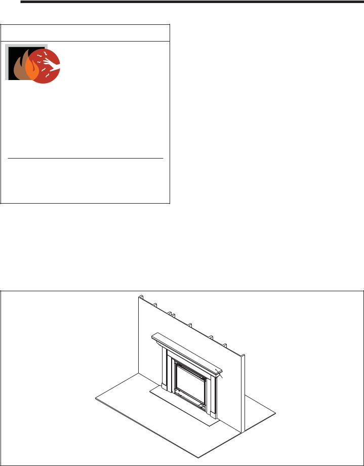
B. Your Fireplace
WARNING! DO NOT operate fireplace before reading and understanding operating instructions. Failure to operate fireplace according to operating instructions could cause fire or injury.
DECORATIVE DOORS
(NOT SHOWN)
SECTION 2.E.
FIXED GLASS ASSEMBLY
SECTION 14.G.
MANTEL
SECTION 5.D
HEARTH
CLEAR SPACE
SECTION 2.D.
Figure 2.1 General Operating Parts
Heat & Glo • ST-36TR-IPI, PIER-36TR-IPI • 2176-900 Rev. F • 8/11 |
9 |
C. Blower Kit (optional)
If desired, a blower kit may be added. Contact your dealer to order the correct blower kit.
Blower Installation
1.Place blower in appliance as shown in Figure 2.2.
2.Wire the blower and temperature sensor as shown in Figure 12.2.
3.Attach temperature sensor switch by placing the switch onto the threaded stud indicated in Figure 2.2 and then threading the wing nut onto the stud.
E. Decorative Doors and Fronts
WARNING! Risk of Fire! Install ONLY doors or fronts approved by Hearth & Home Technologies. Unapproved doors or fronts may cause fireplace to overheat.
This fireplace has been supplied with an integral barrier to prevent direct contact with the fixed glass panel. DO NOT operate the fireplace with the barrier removed.
Contact your dealer or Hearth & Home Technologies if the barrier is not present or help is needed to properly install one.
|
THREADED STUD |
Figure 2.2 |
Blower Location |
For more information refer to the instructions supplied with your decorative door or front.
F. Fixed Glass Assembly
See Section 14.G.
G.Remote Controls, Wall Controls and Wall Switches
Follow the instructions supplied with the control installed to operate your fireplace:
For safety:
•Install a switch lock or a wall/remote control with child protection lockout feature.
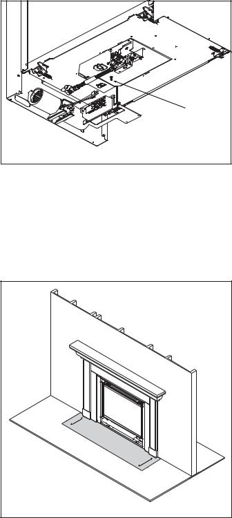
D. Clear Space
WARNING! DO NOT place combustible objects in front of the fireplace or block louvers. High temperatures may start a fire. See Figure 2.3.
Avoid placing candles and other heat-sensitive objects on mantel or hearth. Heat may damage these objects.
• Keep remote controls out of reach of children. See your dealer if you have questions.
H. Before Lighting Fireplace
Before operating this fireplace for the first time, have a qualified service technician:
|
|
|
|
|
• |
Verify all shipping materials have been removed from |
|
|
|
|
|
|
inside and/or underneath the firebox. |
|
|
|
|
|
• Review proper placement of logs, ember material and/or |
|
|
|
|
|
|
|
other decorative materials. |
|
|
|
|
|
• |
Check the wiring. |
|
|
|
|
|
• |
Check the air shutter adjustment. |
|
|
|
|
|
• |
Ensure that there are no gas leaks. |
|
|
|
|
|
• Ensure that the glass is sealed and in the proper position |
|
|
|
|
|
|
|
and that the integral barrier is in place. |
|
|
|
|
|
WARNING! Risk of Fire or Asphyxiation! DO NOT op- |
|
|
|
|
|
|
erate fireplace with fixed glass assembly removed. |
|
|
3 |
FT. |
CLEAR |
|
|
|
|
|
|
|
|
||
|
|
IN |
|
|
|
|
|
|
|
FRONT OFSPACE |
|
|
|
|
|
|
FIREPLACE |
|
|
|
Figure 2.3 |
Clear Space |
|
|
|
|
|
10 |
|
|
Heat & Glo |
• |
ST-36TR-IPI, PIER-36TR-IPI • 2176-900 Rev. F • 8/11 |
|
I. Lighting Instructions (IPI)
The IPI system may be operated with two D-cell batteries. To prolong battery life, remove them when using the transformer.
FOR YOUR SAFETY
READ BEFORE LIGHTING
WARNING: If you do not follow these instructions exactly, a fire or explosion may result causing property damage, personal injury or loss of life.
A.This appliance is equipped with an intermittent pilot ignition (IPI) device which automatically lights the burner. DO NOT try to light the burner by hand.
B.BEFORE LIGHTING, smell all around the appliance area for gas. Be sure to smell next to the floor because some gas is heavier than air and will settle on the floor.
WHAT TO DO IF YOU SMELL GAS
•DO NOT try to light any appliance.
•DO NOT touch any electric switch; do not use any phone in your building.
•Immediately call your gas supplier from a neighbor’s phone. Follow the gas supplier’s instructions.
•If you cannot reach your gas supplier, call the fire department.
C.DO NOT use this appliance if any part has been under water. Immediately call a qualified service technician to inspect the appliance and to replace any part of the control system and any gas control which has been under water.
WARNING: 
 CAUTION:
DO NOT CONNECT LINE VOLTAGE (110/120 VAC OR 220/240 VAC) TO THE CONTROL VALVE.
Improper installation, adjustment, alteration, service or maintenance can cause injury or property damage. Refer to the owner’s information manual provided with this appliance.
This appliance needs fresh air for safe operation and must be installed so there are provisions for adequate combustion and ventilation air.
If not installed, operated, and maintained in accordance with the manufacturer’s instructions, this product could expose you to substances in fuel or fuel combustion which are known to the State of California to cause cancer, birth defects, or other reproductive harm.
Keep burner and control compartment clean. See installation and operating instructions accompanying appliance.
Hot while in operation. DO NOT touch. Keep children, clothing, furniture, gasoline and other liquids having flammable vapors away.
DO NOT operate the appliance with fixed glass assembly removed, cracked or broken. Replacement of the fixed glass assembly should be done by a licensed or qualified service person.
NOT FOR USE
WITH SOLID FUEL
For use with natural gas and propane. A conversion kit, as supplied by the manufacturer, shall be used to convert this appliance to the alternate fuel.
Also Certified for Installation in a Bedroom or a Bedsitting Room.
For assistance or additional information, consult a qualified installer, service agency or the gas supplier.
For additional information on operating your
Hearth & Home Technologies fireplace, please refer to www.fireplaces.com.

 LIGHTING
INSTRUCTIONS (IPI)
1.This appliance is equipped with an ignition device which automatically lights the burner. DO NOT try to light the burner by hand.
GAS
VALVE
2.Wait five (5) minutes to clear out any gas. Then smell for gas, including near the floor. If you smell gas, STOP! Follow “B” in the Safety Information located on the left side of this label. If you do not smell gas, go to next step.
3.To light the burner:
Equipped with wall switch: Turn ON/OFF switch to ON.
Equipped with remote or wall control: Press ON or FLAME button.
Equipped with thermostat: Set temperature to desired setting.
4.If the appliance does not light after three tries, call your service technician or gas supplier.

 TO TURN OFF
 GAS TO APPLIANCE
1.Equipped with wall switch: Turn ON/OFF switch to OFF.
Equipped with remote or wall control: Press OFF button.
Equipped with thermostat: Set temperature to lowest setting.
2.Service technician should turn off electric power to the control when performing service.
593-913G
Final inspection by
Heat & Glo • ST-36TR-IPI, PIER-36TR-IPI • 2176-900 Rev. F • 8/11 |
11 |

J. After Fireplace is Lit
Initial Break-in Procedure
•The fireplace should be run three to four hours continuously on high.
•Turn the fireplace off and allow it to completely cool.
•Remove fixed glass assembly. See Section 14.G.
•Clean fixed glass assembly. See Section 3.
•Replace the fixed glass assembly and run continuously on high an additional 12 hours.
This cures the materials used to manufacture the fireplace.
NOTICE! Open windows for air circulation during fireplace break-in.
•Some people may be sensitive to smoke and odors.
•Smoke detectors may activate.
K.Frequently Asked Questions
ISSUE |
SOLUTIONS |
|
|
|
|
Condensation on the glass |
This is a result of gas combustion and temperature variations. As the fireplace warms, this |
|
condensation will disappear. |
||
|
||
|
|
|
Blue flames |
This is a result of normal operation and the flames will begin to yellow as the fireplace is al- |
|
lowed to burn for 20 to 40 minutes. |
||
|
||
|
|
|
|
When first operated, this fireplace may release an odor for the first several hours. This is |
|
Odor from fireplace |
caused by the curing of materials from manufacturing. Odor may also be released from |
|
finishing materials and adhesives used near the fireplace. These circumstances may require |
||
|
||
|
additional curing related to the installation environment. |
|
|
|
|
Film on the glass |
This is a normal result of the curing process of the paint and logs. Glass should be cleaned |
|
within 3 to 4 hours of initial burning. A non-abrasive cleaner such as gas fireplace glass |
||
|
||
|
cleaner may be necessary. See your dealer. |
|
|
|
|
|
Noise is caused by metal expanding and contracting as it heats up and cools down, similar to |
|
Metallic noise |
the sound produced by a furnace or heating duct. This noise does not affect the operation or |
|
|
longevity of the fireplace. |
|
|
|
12 |
Heat & Glo • ST-36TR-IPI, PIER-36TR-IPI • 2176-900 Rev. F • 8/11 |

3 Maintenance and Service
Any safety screen or guard removed for servicing must be replaced prior to operating the fireplace.
When properly maintained, your fireplace will give you many years of trouble-free service. We recommend annual service by a qualified service technician.
Doors, Surrounds, Fronts
Frequency: Annually
By: Homeowner
Tools needed: Protective gloves, stable work surface
• Assess condition of screen and replace as necessary.
A. Maintenance Tasks-Homeowner
Installation and repair should be done by a qualified service technician only. The fireplace should be inspected before use and at least annually by a professional service person.
The following tasks may be performed annually by the homeowner. If you are uncomfortable performing any of the listed tasks, please call your dealer for a service appointment.
More frequent cleaning may be required due to lint from carpeting or other factors. Control compartment, burner and circulating air passageway of the fireplace must be kept clean.
CAUTION! Risk of Burns! The fireplace should be turned off and cooled before servicing.
Glass Cleaning
Frequency: Seasonally
By: Homeowner
Tools Needed: Protective gloves, glass cleaner, drop cloth and a stable work surface.
CAUTION! Handle fixed glass assembly with care.
Glass is breakable.
•Avoid striking, scratching or slamming glass
•Avoid abrasive cleaners
•DO NOT clean glass while it is hot
•Prepare a work area large enough to accommodate fixed glass assembly and door frame by placing a drop cloth on a flat, stable surface.
Note: Fixed glass assembly and gasketing may have residue that can stain carpeting or floor surfaces.
•Remove door or decorative front from fireplace and set aside on work surface.
•See Section 14.G for instructions to remove fixed glass assembly.
•Clean glass with a non-abrasive commercially available cleaner.
-Light deposits: Use a soft cloth with soap and water
-Heavy deposits: Use commercial fireplace glass cleaner (consult with your dealer)
•Carefully set fixed glass assembly in place on fireplace. Hold glass in place with one hand and secure glass latches with the other hand.
•Reinstall door or decorative front.
•Inspect for scratches, dents or other damage and repair as necessary.
•Check that louvers are not blocked.
•Vacuum and dust surfaces.
Remote Control
Frequency: Seasonally
By: Homeowner
Tools needed: Replacement batteries and remote control instructions.
•Locate remote control transmitter and receiver.
•Verify operation of remote. Refer to remote control operation instructions for proper calibration and setup procedure.
•Place batteries as needed in remote transmitters and battery-powered receivers.
•Place remote control out of reach of children.
If not using your fireplace for an extended period of time (summer months, vacations/trips, etc), to prevent unintended operation:
•Remove batteries from remote controls.
•Unplug 3 volt adapter plug on IPI models.
Venting
Frequency: Seasonally
By: Homeowner
Tools needed: Protective gloves and safety glasses.
•Inspect venting and termination cap for blockage or obstruction such plants, bird nests, leaves, snow, debris, etc.
•Verify termination cap clearance to subsequent construction (building additions, decks, fences, or sheds). See Section 6.
•Inspect for corrosion or separation.
•Verify weather stripping, sealing and flashing remains intact.
•Inspect draft shield to verify it is not damaged or missing.
Heat & Glo • ST-36TR-IPI, PIER-36TR-IPI • 2176-900 Rev. F • 8/11 |
13 |
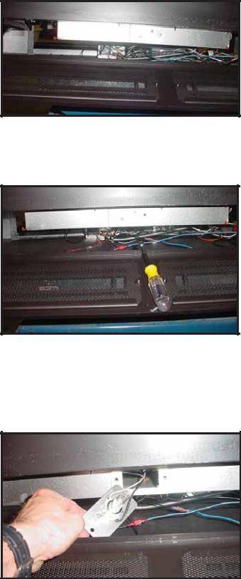
Ember Light Replacement
Frequency: As Required
By: Homeowner or Qualified Service Technician
Tools needed: Protective gloves, 5/16 in. nut driver
In the lower gas valve compartment you will find three access panels for the three light bulbs. See Figure 3.1
Figure 3.1 Access Panel
1.Unplug the electrical cord as shown Figure 13.1.
2.Remove the two bolts using a 5/16 in. nut driver. See Figure 3.2.
Figure 3.2 Remove Bolts
B.Maintenance Tasks-Qualified Service Technician
The following tasks must be performed by a qualified service technician.
Gasket Seal and Glass Assembly Inspection
Frequency: Annually
By: Qualified Service Technician
Tools needed: Protective gloves, drop cloth and a stable work surface.
•Inspect gasket seal and its condition.
•Inspect fixed glass assembly for scratches and nicks that can lead to breakage when exposed to heat.
•Confirm there is no damage to glass or glass frame. Replace as necessary.
•Verify that fixed glass assembly is properly retained and attachment components are intact and not damaged. Replace as necessary.
Logs
Frequency: Annually
By: Qualified Service Technician
Tools needed: Protective gloves.
•Inspect for damaged or missing logs. Replace as necessary. Refer to Section 14 for log placement instructions.
•Verify correct log placement and no flame impingement causing sooting. Correct as necessary.
Firebox
Frequency: Annually
By: Qualified Service Technician
Tools needed: Protective gloves, sandpaper, steel wool, cloths, mineral spirits, primer and touch-up paint.
3.Pull the access panel to expose the light bulb. Wearing clean cotton gloves, replace the bulb. Any skin oils which get on a new bulb will greatly reduce the life of the bulb. The bulb can be cleaned with isopropyl alcohol. See Figure 3.3.
Figure 3.3 Replace Bulb
•Inspect for paint condition, warped surfaces, corrosion or perforation. Sand and repaint as necessary.
•Replace fireplace if firebox has been perforated.
Control Compartment and Firebox Top
Frequency: Annually
By: Qualified Service Technician
Tools needed: Protective gloves, vacuum cleaner, dust cloths
•Vacuum and wipe out dust, cobwebs, debris or pet hair. Use caution when cleaning these areas. Screw tips that have penetrated the sheet metal are sharp and should be avoided.
•Remove all foreign objects.
•Verify unobstructed air circulation.
14 |
Heat & Glo • ST-36TR-IPI, PIER-36TR-IPI • 2176-900 Rev. F • 8/11 |
Burner Ignition and Operation
Frequency: Annually
By: Qualified Service Technician
Tools needed: Protective gloves, vacuum cleaner, whisk broom, flashlight, voltmeter, indexed drill bit set, and a manometer.
•Verify burner is properly secured and aligned with pilot or igniter.
•Clean off burner top, inspect for plugged ports, corrosion or deterioration. Replace burner if necessary.
•Replace ember materials with new dime-size pieces. DO NOT block ports or obstruct lighting paths. Refer to Section 14 for proper ember placement.
•Verify batteries have been removed from battery backup IPI systems to prevent premature battery failure or leaking.
•Check for smooth lighting and ignition carryover to all ports. Verify that there is no ignition delay.
•Inspect for lifting or other flame problems.
•Verify air shutter setting is correct. See Section 14 for required air shutter setting. Verify air shutter is clear of dust and debris.
•Inspect orifice for soot, dirt and corrosion. Verify orifice size is correct. See Service Parts List for proper orifice sizing.
•Verify manifold and inlet pressures. Adjust regulator as required.
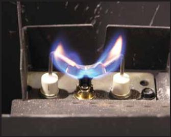
•Inspect pilot flame pattern and strength. See Figure 3.4 for proper pilot flame pattern. Clean or replace orifice spud as necessary.
•Inspect IPI flame-sensing rod for soot, corrosion and
deterioration. Polish with fine steel wool or replace as required.
•Verify that there is not a short in flame sense circuit by checking continuity between pilot hood and flamesensing rod. Replace pilot as necessary.
Figure 3.4 IPI Pilot Flame Patterns
Heat & Glo • ST-36TR-IPI, PIER-36TR-IPI • 2176-900 Rev. F • 8/11 |
15 |

4 |
Getting Started |
Installer Guide |
|
||
|
|
A. Typical Appliance System
NOTICE: Illustrations and photos reflect typical installations and are for design purposes only. Illustrations/diagrams are not drawn to scale. Actual product may vary from pictures in manual
HORIZONTAL |
TERMINATION CAP |
(SECTION 10.M ) |
NON-COMBUSTIBLE ROOF FLASHING
MAINTAINS MINIMUM CLEARANCE
AROUND PIPE (SECTION 10.G) 
VERTICAL TERMINATION CAP (SECTION 10.J)
STORM COLLAR (SECTION 10.H)
VENT PIPE PENETRATES ROOF
PREFERABLY WITHOUT AFFECTING
ROOF RAFTERS (SECTION 8.C )
FRAMING/HEADER (SECTION 5.B)
Note: Dual venting configurations ARE NOT allowed. Appliance MUST be vented EITHER vertically OR horizontally.
ATTIC INSULATION SHIELD (NOT
SHOWN) MUST BE USED HERE
TO KEEP INSULATION AWAY
FROM VENT PIPE IF ATTIC IS
INSULATED (SECTION 8.D )
VENT PIPE (SECTION 9 and 10)
FRAMING HEADED OFF
IN CEILING JOISTS
(SECTION 8.C)


 CEILING FIRESTOP
ON FLOOR OF ATTIC (SECTION 8.C)
WALL SWITCH
SECTION 12.E.
GAS LINE (SECTION 11.C)
HEARTH EXTENSION
SURROUND
MANTEL AND MANTEL LEG (SECTION 5.D)
Figure 4.1 Typical System
16 |
Heat & Glo • ST-36TR-IPI, PIER-36TR-IPI • 2176-900 Rev. F • 8/11 |

B. Design and Installation Considerations
Heat & Glo direct vent gas appliances are designed to operate with all combustion air siphoned from outside of the building and all exhaust gases expelled to the outside. No additional outside air source is required.
Installation MUST comply with local, regional, state and national codes and regulations. Consult insurance carrier, local building inspector, fire officials or authorities having jurisdiction over restrictions, installation inspection and permits.
Before installing, determine the following:
•Where the appliance is to be installed.
•The vent system configuration to be used.
•Gas supply piping.
•Electrical wiring requirements.
•Framing and finishing details.
•Whether optional accessories—devices such as a fan, wall switch, or remote control—are desired.
Improper installation, adjustment, alteration, service or maintenance can cause injury or property damage. For assistance or additional information, consult a qualified service technician, service agency or your dealer.
C. Tools and Supplies Needed
Before beginning the installation be sure that the following tools and building supplies are available.
Tape measure |
Framing material |
Pliers |
Non-corrosive leak check solution |
Hammer |
Phillips screwdriver |
Gloves |
Framing square |
Voltmeter |
Electric drill and bits (1/4 in.) |
Plumb line |
Safety glasses |
Level |
Reciprocating saw |
Manometer |
Flat blade screwdriver |
1/2 - 3/4 in. length, #6 or #8 Self-drilling screws
Caulk (minimum of 300ºF continuous exposure rating) One 1/4 in. female connection (for optional fan).
D. Inspect Appliance and Components
•Carefully remove the appliance and components from the packaging.
•The vent system components and decorative doors and fronts may be shipped in separate packages.
•If packaged separately, the log set and appliance grate must be installed.
•Report to your dealer any parts damaged in shipment, particularly the condition of the glass.
•Read all of the instructions before starting the installation. Follow these instructions carefully during the installation to ensure maximum safety and benefit.
WARNING! Risk of Fire or Explosion! Damaged parts could impair safe operation. DO NOT install damaged, incomplete or substitute components. Keep appliance dry.
Hearth & Home Technologies disclaims any responsibility for, and the warranty will be voided by, the following actions:
•Installation and use of any damaged appliance or vent system component.
•Modification of the appliance or vent system.
•Installation other than as instructed by Hearth & Home Technologies.
•Improper positioning of the gas logs or the glass door.
•Installation and/or use of any component part not approved by Hearth & Home Technologies.
Any such action may cause a fire hazard.
WARNING! Risk of Fire, Explosion or Electric Shock! DO NOT use this appliance if any part has been under water. Call a qualified service technician to inspect the appliance and to replace any part of the control system and/or gas control which has been under water.
Heat & Glo • ST-36TR-IPI, PIER-36TR-IPI • 2176-900 Rev. F • 8/11 |
17 |
5 Framing and Clearances
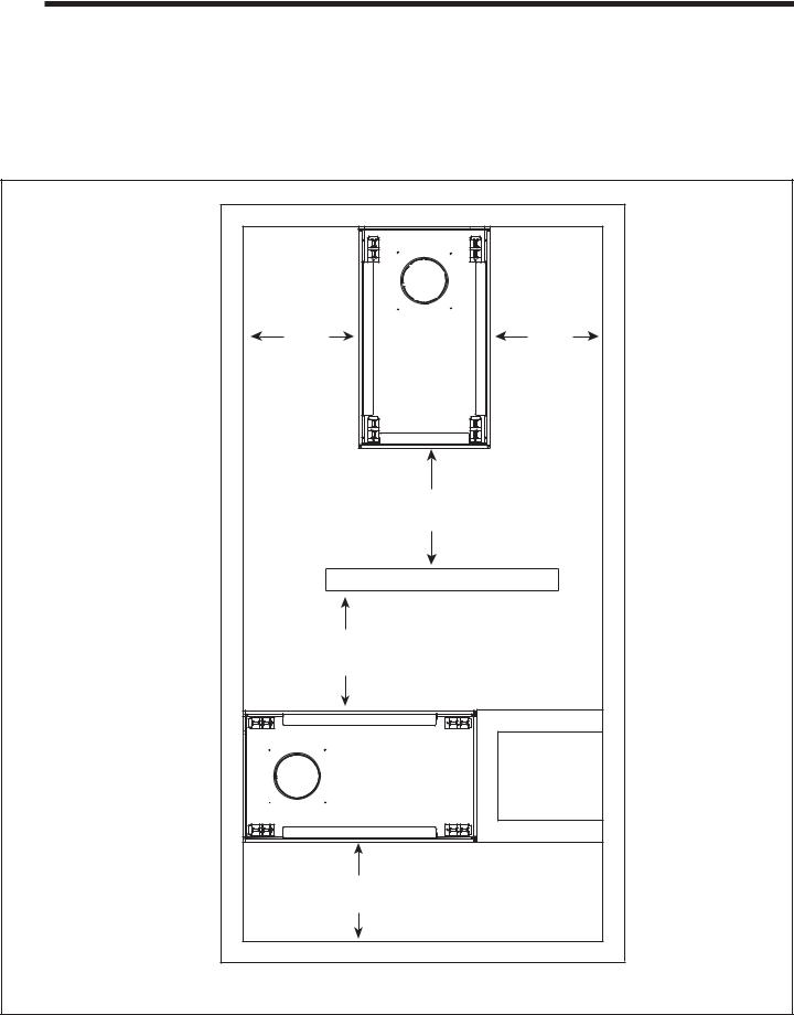
A. Selecting Appliance Location
When selecting a location for the appliance it is important to consider the required clearances to walls (see Figure 5.1).
WARNING! Risk of Fire or Burns! Provide adequate clearance around air openings and for service access.
Due to high temperatures, the appliance should be located out of traffic and away from furniture and draperies.
NOTICE: Illustrations reflect typical installations and are FOR DESIGN PURPOSES ONLY. Illustrations/diagrams are not drawn to scale. Actual installation may vary due to individual design preference.
|
|
|
36 in. |
|
36 in. |
|
|
|
914 mm |
|
914 mm |
|
|
|
PIER |
|
|
|
|
|
36 in. |
|
|
|
|
|
914 mm |
||
|
|
|
36 in. |
|
|
|
|
|
914 mm |
|
|
|
|
|
ST |
|
|
|
|
|
36 in. |
|
|
|
|
|
914 mm |
|
|
Figure 5.1 |
Appliance Locations |
|
|
|
|
18 |
Heat & Glo |
• |
ST-36TR-IPI, PIER-36TR-IPI |
• |
2176-900 Rev. F • 8/11 |
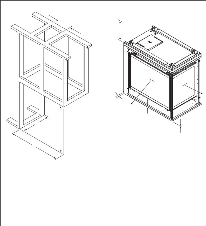
B. Constructing the Appliance Chase
A chase is a vertical box-like structure built to enclose the gas appliance and/or its vent system. In cooler climates the vent should be enclosed inside the chase.
NOTICE: Treatment of ceiling firestops and wall shield firestops and construction of the chase may vary with the type of building. These instructions are not substitutes for the requirements of local building codes. Therefore, you MUST check local building codes to determine the requirements to these steps.
Chases should be constructed in the manner of all outside walls of the home to prevent cold air drafting problems. The chase should not break the outside building envelope in any manner.
Walls, ceiling, base plate and cantilever floor of the chase should be insulated. Vapor and air infiltration barriers should be installed in the chase as per regional codes for the rest of the home. Additionally, in regions where cold air infiltration may be an issue, the inside surfaces may be sheetrocked and taped for maximum air tightness.
To further prevent drafts, the wall shield and ceiling firestops should be caulked with caulk with a minimum of
300ºF continuous exposure rating to seal gaps. Gas line holes and other openings should be caulked with caulk with a minimum of 300ºF continuous exposure rating or stuffed with unfaced insulation. If the appliance is being installed on a cement slab, a layer of plywood may be placed underneath to prevent conducting cold up into the room.
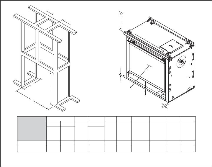
C. Clearances
NOTICE: Install appliance on hard metal or wood surfaces extending full width and depth. DO NOT install directly on carpeting, vinyl, tile or any combustible material other than wood.
WARNING! Risk of Fire! Maintain specified air space clearances to appliance and vent pipe:
•Insulation and other materials must be secured to prevent accidental contact.
•The chase must be properly blocked to prevent blown insulation or other combustibles from entering and making contact with fireplace or chimney.
•Failure to maintain airspace may cause overheating and a fire.
 A
A
E
|
|
|
|
|
|
|
I |
|
|
|
C |
|
|
|
|
|
F |
|
|
|
|
|
B |
|
|
|
|
|
|
|
|
|
D |
|
|
|
|
|
|
G |
|
|
|
|
|
|
|
|
|
|
|
|
|
|
|
|
|
|
|
|
|
|
|
H |
|
|
A |
|
B |
C |
D |
E |
F |
G |
H |
I |
|
DVP Pipe |
SLP Pipe |
Rough |
DVP Pipe* |
Rough |
|
|
|
|
|
ST-36TR-IPI |
Rough |
Rough |
Rough |
Clearance |
Combustible |
Combustible |
Ends of |
Sides of |
||
|
Opening |
Opening |
to Ceiling |
Floor |
Flooring |
Appliance |
Appliance |
|||
|
Opening |
Opening |
Opening |
|||||||
|
(Height) |
(Width) |
|
|
|
|
|
|||
|
(Width) |
(Width) |
|
(Depth) |
|
|
|
|
|
|
Inches |
10 |
9 |
38-1/8 |
23 |
43 |
29-1/2 |
0 |
0 |
1/2 |
36 |
Millimeters |
254 |
229 |
968 |
584 |
1092 |
749 |
0 |
0 |
13 |
914 |
* Adjust framing dimensions for interior sheathing (such as sheetrock)
Figure 5.2 Clearances to Combustibles ST-36TR-IPI
Heat & Glo • ST-36TR-IPI, PIER-36TR-IPI • 2176-900 Rev. F • 8/11 |
19 |
 A
A
E
I |
I |
H
G
C
B
F
D
|
A |
|
B |
C |
D |
E |
F |
G |
H |
I |
|
|
DVP Pipe |
|
SLP Pipe |
Rough |
DVP Pipe* |
Rough |
|
|
|
|
|
PIER-36TR-IPI |
|
|
|
|
Clearance |
Combustible |
Combustible |
Ends of |
Sides of |
||
Rough |
|
Rough |
Rough |
||||||||
|
|
Opening |
Opening |
to Ceiling |
Floor |
Flooring |
Appliance |
Appliance |
|||
|
Opening |
|
Opening |
Opening |
|||||||
|
|
(Height) |
(Width) |
|
|
|
|
|
|||
|
(Width) |
|
(Width) |
|
(Depth) |
|
|
|
|
|
|
Inches |
10 |
|
8-5/8 |
38-1/8 |
23 |
40 |
31-5/8 |
0 |
0 |
1/2 |
36 |
Millimeters |
254 |
|
219 |
968 |
584 |
1046 |
803 |
0 |
0 |
13 |
914 |
* Adjust framing dimensions for interior sheathing (such as sheetrock)
Figure 5.3 Clearances to Combustibles PIER-36TR-IPI
20 |
Heat & Glo • ST-36TR-IPI, PIER-36TR-IPI • 2176-900 Rev. F • 8/11 |
D. Mantel and Wall Projections
WARNING! Risk of Fire! Comply with all minimum clearances as specified. Framing or finishing material closer than the minimums listed must be constructed entirely of noncombustible materials (i.e., steel studs, concrete board, etc).
See-Through Combustible Mantel |
||||
Note: All |
|
|
|
TO CEILING |
measurements |
|
|
18 |
|
in inches. |
|
|
|
|
|
|
|
|
|
|
|
|
12 |
|
|
|
|
11 |
|
|
|
|
10 |
32 |
|
|
|
9 |
|
|
|
|
25 |
|
|
|
|
8 |
|
|
|
|
7 |
19 |
|
|
|
6 |
|
|
|
|
18 |
|
|
|
|
5 |
|
|
|
|
17 |
|
|
|
3 |
4 |
16 |
|
|
15 |
||
|
|
|
||
|
|
|
|
|
|
|
|
14 |
|
|
|
|
13 |
|
|
2-1/2 |
|
12 |
|
|
|
11 |
|
|
|
|
|
|
|
|
|
|
10 |
|
|
|
|
5 |
|
|
|
|
MEASUREMENTS FROM |
|
|
|
|
TOP EDGE OF THE OPENING |
|
Figure 5.5 |
Minimum Vertical and Maximum Horizontal |
|||
|
Dimensions of Combustibles |
|
||
PIER Combustible Mantel |
|
|||
Note: All |
|
|
|
TO CEILING |
measurements |
|
|
18 |
|
in inches. |
|
|
|
|
|
|
|
|
|
|
|
|
12 |
|
|
|
|
11 |
|
|
|
|
10 |
32 |
|
|
|
9 |
|
|
|
|
25 |
|
|
|
|
8 |
|
|
|
|
7 |
19 |
|
|
|
6 |
|
|
|
|
18 |
|
|
|
|
5 |
|
|
|
|
17 |
|
|
|
3 |
4 |
16 |
|
|
15 |
||
|
|
|
||
|
|
|
|
|
|
|
|
14 |
|
|
|
|
13 |
|
|
1 |
|
12 |
|
|
|
11 |
|
|
|
|
|
|
|
|
|
|
10 |
|
|
|
|
5 |
|
|
|
|
MEASUREMENTS FROM |
|
|
|
|
TOP EDGE OF THE OPENING |
|
Figure 5.6 |
Minimum Vertical and Maximum Horizontal |
|||
|
Dimensions of Combustibles |
|
||
See-Through Non-Combustible Mantel
|
|
|
|
|
TO CEILING |
|
|
Note: All |
|
MAX. |
|
|
|
|
|
|
|
|
|
|
|
|
|
measurements |
|
|
|
18 |
|
|
|
in inches. |
|
|
|
|
|
|
|
|
|
|
|
|
|
|
|
|
|
|
|
|
12 |
|
|
|
|
|
|
|
11 |
32 |
|
|
|
|
|
|
|
|
|
|
|
|
|
|
10 |
12 |
MIN. |
|
|
|
|
|
|
||
|
|
|
|
|
|
|
|
|
|
|
|
|
9 |
|
|
|
|
|
|
|
6 |
|
|
|
|
|
|
8 |
5 |
|
|
|
|
|
|
4 |
|
|
|
|
|
|
|
|
|
|
|
|
|
|
7 |
|
3 |
|
|
|
|
|
|
2 |
|
|
|
|
|
|
|
|
|
|
|
|
|
6 |
|
|
1 |
|
|
|
|
|
|
|
|
|
|
|
|
|
MEASUREMENTS FROM |
|
|
||
|
|
TOP EDGE OF THE OPENING |
|
|
|||
Figure 5.7 Minimum Vertical and Maximum Horizontal |
|
||||||
|
Dimensions of Non-Combustibles |
|
|
||||
PIER Non-Combustible Mantel
|
TO CEILING |
|
|
MAX. |
|
|
|
Note: All |
12 |
|
|
measurements |
|
|
|
in inches. |
|
|
|
|
10 |
|
|
|
9 |
|
|
|
8 |
32 |
|
|
|
|
|
|
7 |
12 |
MIN. |
|
|
|
|
6 |
10 |
|
|
|
9 |
|
|
|
8 |
|
|
|
7 |
|
|
|
6 |
|
|
4 |
|
|
|
MEASUREMENTS FROM |
|
|
|
TOP EDGE OF THE OPENING |
|
|
|
Figure 5.8 Minimum Vertical and Maximum Horizontal |
|
||
Dimensions of Non-Combustibles |
|
|
|
Heat & Glo • ST-36TR-IPI, PIER-36TR-IPI • 2176-900 Rev. F • 8/11 |
21 |
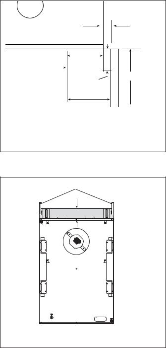
TOP VIEW |
1/2 in. |
Min. |
FIREPLACE |
2-3/4 |
||
OPENING |
|
|
in. Min. |
|
|||
1 in. |
|
Unlimited |
|
||
|
||
|
|
|
Max. |
|
|
3-1/4 in. Min.

Note: Clearance from opening to perpendicular wall.
Figure 5.9 Combustible Mantel Leg or Wall Projections (Acceptable on both sides of opening)
SHEETROCK
3.5 in.
 AIR SPACE REQUIRED
Figure 5.10 Non-Combustible Zone
22 |
Heat & Glo • ST-36TR-IPI, PIER-36TR-IPI • 2176-900 Rev. F • 8/11 |
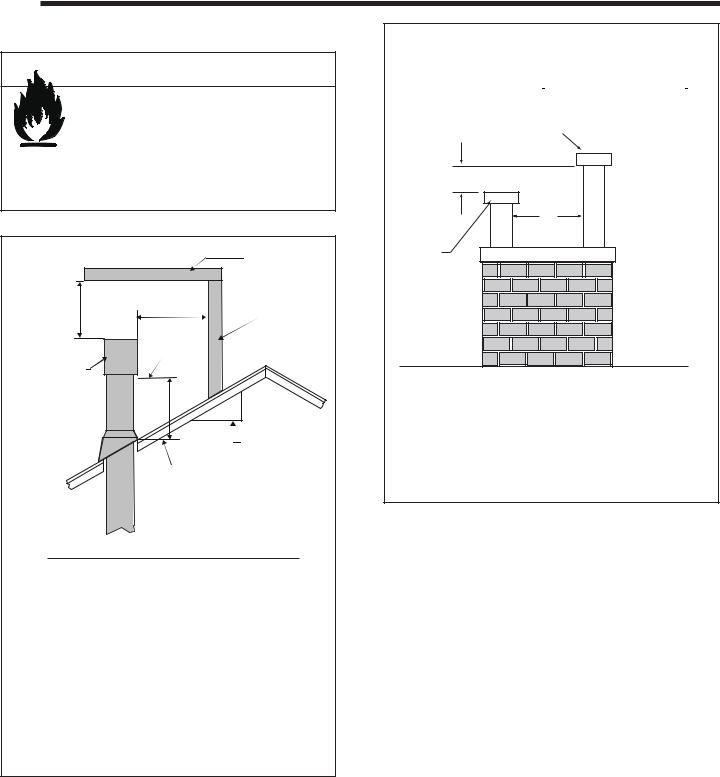
6 Termination Locations
A. Vent Termination Minimum Clearances
 WARNING
Fire Risk.
Maintain vent clearance to combustibles as specified.
• DO NOT pack air space with insulation or other materials.
Failure to keep insulation or other materials away from vent pipe may cause overheating and fire.
|
|
HORIZONTAL |
|
|
OVERHANG |
2 FT. |
20 INCHES MIN. |
VERTICAL |
MIN. |
|
|
|
WALL |
|
|
LOWEST |
|
|
|
|
|
DISCHARGE |
|
|
OPENING |
|
GAS DIRECT VENT |
|
|
TERMINATION CAP |
|
|
|
|
X |
|
|
12 |
|
|
ROOF PITCH |
|
|
IS X/ 12 |
|
H (MIN.) - MINIMUM HEIGHT FROM ROOF |
|
|
TO LOWEST DISCHARGE OPENING |
|
Roof Pitch |
|
H (Min.) Ft. |
Flat to 6/12...........................................................1.0* |
||
Over 6/12 to 7/12.................................................1.25* |
||
Over 7/12 to 8/12.................................................1.5* |
||
Over 8/12 to 9/12.................................................2.0* |
||
Over 9/12 to 10/12...............................................2.5* |
||
Over 10/12 to 11/12 .............................................3.25 |
||
Over 11/12 to 12/12 .............................................4.0 |
||
Over 12/12 to 14/12.............................................5.0 |
||
Over 14/12 to 16/12.............................................6.0 |
||
Over 16/12 to 18/12.............................................7.0 |
||
Over 18/12 to 20/12.............................................7.5 |
||
Over 20/12 to 21/12.............................................8.0 |
||
* 3 foot minimum in snow regions |
||
Figure 6.1 Minimum Height From Roof To Lowest Discharge |
||
Opening |
|
|
A |
B |
6 in. (minimum) up to 20 in. |
18 in. minimum |
152 mm/508 mm |
457 mm |
20 in. and over |
0 in. minimum |
Gas, Wood or Fuel Oil
Termination Cap
B
A *
Gas
Termination
Cap **
*If using decorative cap cover(s), this distance may need to be increased. Refer to the installation instructions supplied with the decorative cap cover.
**In a staggered installation with both gas and wood or fuel oil terminations, the wood or fuel oil termination cap must be higher than the gas termination cap.
Figure 6.2 Staggered Termination Caps
Heat & Glo • ST-36TR-IPI, PIER-36TR-IPI • 2176-900 Rev. F • 8/11 |
23 |
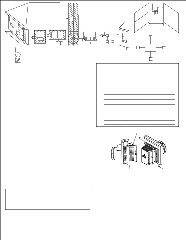
|
|
|
|
|
|
|
|
|
|
|
O |
|
N |
|
|
|
|
|
|
|
|
|
|
|
|
|
|
|
|
|
|
|
|
|
|
|
|
|
P |
|
|
C |
|
|
|
F |
|
|
|
|
|
R |
|
|
|
|
|
|
|
|
|
|
|
|
|
|
|
|
|
V |
|
|
|
|
|
|
|
|
|
|
|
Q |
|
J |
B |
|
|
|
|
|
|
|
|
|
|
|
|
|
|
B |
|
|
H or i |
|
|
|
|
|
|
||
|
V |
|
B |
|
|
|
|
|
|
|
|||
|
|
V |
|
|
|
|
|
|
|
|
|
||
|
|
D |
X |
V |
|
E |
|
|
V |
|
|
||
|
|
G |
|
|
|
|
|
||||||
|
|
V |
|
H |
|
|
|
|
|
|
|||
|
|
|
V |
M |
|
|
V |
|
|
|
|
|
|
|
|
|
V |
V |
H V |
|
|
L |
|
|
|||
|
|
|
|
A |
A |
|
|
|
|
||||
|
|
|
|
|
|
|
K |
|
|
|
|||
|
|
|
|
|
|
|
|
V |
Electrical |
K |
V |
||
|
V |
|
|
|
|
|
|
|
|||||
|
= VENT TERMINAL |
|
|
|
|
|
|
|
Service |
|
|
||
|
|
|
|
|
|
|
|
|
|
|
|||
|
|
|
X = AIR SUPPLY INLET |
|
|
|
C |
|
|
|
|
|
|
|
|
|
|
||
|
|
|
= AREA WHERE TERMINAL IS NOT PERMITTED |
|
|
|
V |
|
|
|
A |
= |
12 inches................. |
clearances above grade, veranda, |
|
|
Covered Alcove Applications |
||
|
|
|
|
porch, deck or balcony |
|
|
|||
|
|
|
|
(Spaces open only on one side and with an overhang) |
|||||
|
B |
= |
12 inches |
clearance to window or door that may |
|||||
|
N |
= |
6 inches ........... |
non-vinyl sidewalls |
|||||
|
|
|
|
be opened, or to permanently closed |
|
|
12 inches |
vinyl sidewalls |
|
|
|
|
|
window |
|
|
|||
|
|
|
|
O |
= |
18 inches |
non-vinyl soffit and overhang |
||
|
C |
= |
18 inches |
clearance below unventilated soffit |
|||||
|
|
|
42 inches |
vinyl soffit and overhang |
|||||
|
|
|
18 inches |
clearance below ventilated soffit |
|
|
|||
|
|
|
P |
= |
8 ft. |
|
|
||
|
|
30 inches |
clearance below vinyl soffits and |
|
|
||||
|
|
|
|
|
|
|
|||
|
|
|
|
electrical service |
|
|
|
QMIN |
RMAX |
|
D |
= |
9 inches................... |
clearance to outside corner |
|
1 cap |
3 feet |
2 x Q ACTUAL |
|
|
E |
= |
6 inches................... |
clearance to inside corner |
|
2 caps |
6 feet |
1 x Q ACTUAL |
|
|
F |
= |
3 ft. (Canada) |
not to be installed above a gas me- |
|
||||
|
|
3 caps |
9 feet |
2/3 x Q ACTUAL |
|||||
|
|
|
|
ter/regulator assembly within 3 feet |
|
||||
|
|
|
|
horizontally from the center-line of the |
|
4 caps |
12 feet |
1/2 x Q ACTUAL |
|
|
|
|
|
regulator |
QMIN = # termination caps x 3 RMAX = (2 / # termination caps) x QACTUAL |
||||
|
G |
= |
3 ft |
clearance to gas service regulator |
|||||
|
|
|
|
|
|
||||
|
|
|
|
vent outlet |
|
|
Measure vertical clearances from this surface. |
||
|
H |
= |
9 inches (U.S.A) |
|
|
|
|||
|
|
|
|
|
|
|
|||
|
|
12 inches (Canada) .clearance to non-mechanical (unpow- |
|
|
|
|
|
||
|
|
|
|
ered) air supply inlet, combustion air |
|
|
|
|
|
|
i |
= |
3 ft. (U.S.A.) |
inlet or direct-vent termination |
|
|
|
|
|
|
|
|
|
|
|
|
|||
|
|
|
6 ft. (Canada)........... |
clearance to a mechanical (powered) |
|
|
|
|
|
|
|
|
|
air supply inlet |
|
|
|
|
|
|
All mechanical air intakes within 10 feet of a termination cap |
|
|
|
|
|
|||
|
must be a minimum of 3 feet below termination. |
|
|
|
|
|
|||
|
J |
= |
7 ft.......................... |
On public property: clearance above |
|
|
|
|
|
|
|
|
|
paved sidewalk or a paved driveway. |
|
|
|
|
|
|
A vent shall not terminate directly above a sidewalk or paved |
|
Measure horizontal clearances from this surface. |
||||||
|
driveway which is located between two single family dwellings |
|
|||||||
|
and serves both dwellings. |
|
CAUTION! Risk of Burns! Termination caps are HOT, |
||||||
|
|
|
|
|
|||||
|
|
|
|
|
consider proximity to doors, traffic areas or where people |
||||
|
K |
= |
6 inches |
clearance from sides of electrical |
may pass or gather (sidewalk, deck, patio, etc.). Listed cap |
||||
|
shields available. Contact your dealer. |
|
|||||||
|
|
|
|
service |
• Local codes or regulations may require different |
||||
|
L |
= |
12 inches |
clearance above electrical service |
|||||
|
clearances. |
|
|
||||||
|
Location of the vent termination must not interfere with access to the |
|
|
||||||
|
• Vent system termination is NOT permitted in screened |
||||||||
|
electrical service. |
|
|||||||
|
|
|
|
|
porches. |
|
|
||
|
M |
= |
18 inches .................... |
clearanceunderveranda,porch,deck, |
• Vent system termination is permitted in porch areas with |
||||
|
|
|
|
balcony or overhang |
two or more sides open. |
|
|||
|
|
|
42 inches ................ |
vinyl or composite overhang |
• Hearth & Home Technologies assumes no responsibility |
||||
|
Permitted when veranda, porch, deck or balcony is fully open |
for the improper performance of the appliance when the |
|||||||
|
on a minimum of 2 sides beneath the floor. |
||||||||
|
|
|
|
|
venting system does not meet these requirements. |
||||
|
Figure 6.3 Minimum Clearances for Termination |
• Vinyl protection kits are suggested for use with vinyl siding. |
|||||||
|
24 |
|
|
Heat & Glo • ST-36TR-IPI, PIER-36TR-IPI • |
2176-900 Rev. F • |
8/11 |
|
||
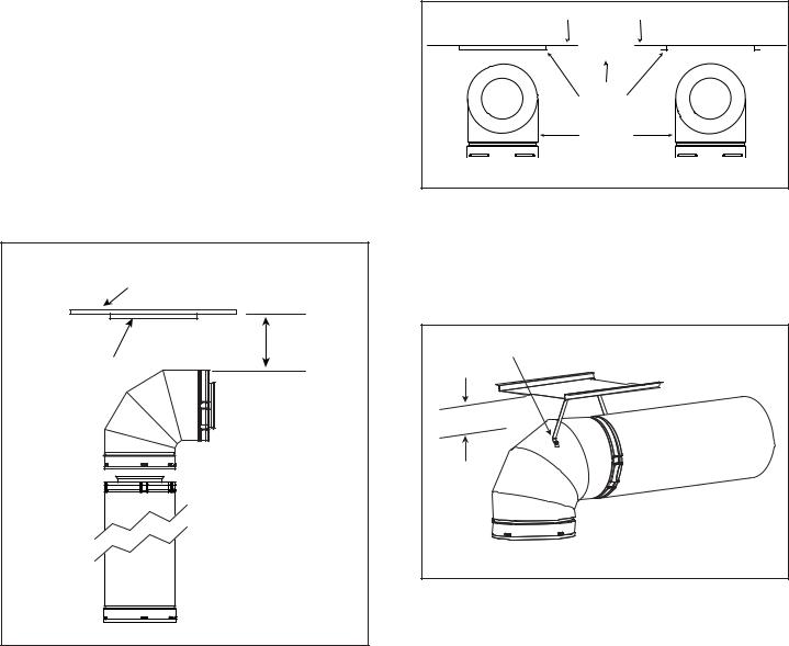
B. Continue Adding Vent Components
WARNING! Risk of Fire! Installation of this appliance may require the use of heat shield 385-920 above the first 900 elbow in the venting system.
To Install the Heat Shield:
1.Determine if the heat shield is required. Do so by measuring the vertical distance between the top horizontal surface of the elbow to any combustible surface above. If the distance is more than 4 inches, the heat shield is NOT required. If it is 4 inches or less, the heat shield IS REQUIRED. Install per the following steps. See Figure 6.4.
COMBUSTIBLE
SURFACE
3 in. MIN. HEAT (76 mm) SHIELD
Figure 6.4
2.Fasten the shield in place using the four pilot holes provided in the part. The shield should be oriented such that the 13-1/8 inch dimension (longest dimension) is running in the same direction the elbow is pointing. The shield should be centered directly above the elbow, and positioned so that it creates a 1/2 inch airspace between the shield and the combustible surface. See Figure 6.5.
CORRECT |
COMBUSTIBLE SURFACE |
INCORRECT |
|
||
|
DIRECTION |
|
|
UP |
|
|
HEAT SHIELD |
|
|
90º ELBOW |
|
Figure 6.5 |
|
|
•If the combustible materials are not in place at the time of install the elbow heat shield may be screwed to the exhaust pipe (see Figure 6.6). Cut the tabs as shown and bend down. Secure the heat shield to the pipe maintaining 3 inch to 4 inch between the pipe and shield.
SCREW |
3 in. |
(76 mm) |
Figure 6.6 |
Refer to DVP Pipe and Termination Cap installation instructions.
•Continue adding vent components, locking each succeeding component into place.
•Ensure that each succeeding vent component is securely fitted and locked into the preceding component in the vent system.
•90º elbows may be installed and rotated to any point around the preceding component’s vertical axis. If an elbow does not end up in a locked position with the preceding component, attach with a minimum of two (2) sheet metal screws.
C. Install Support Brackets
Refer to cinch pipe and termination cap installation instructions.
Heat & Glo • ST-36TR-IPI, PIER-36TR-IPI • 2176-900 Rev. F • 8/11 |
25 |
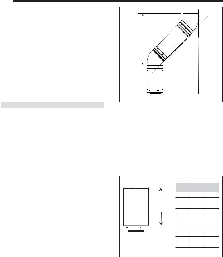
7 Vent Information and Diagrams
A. Approved Pipe
This appliance is approved for use with Hearth & Home Technologies a DVP venting system. Refer to Section 16B for vent component information.
DO NOT mix pipe, fittings or joining methods from different manufacturers.
The pipe is tested to be run inside an enclosed wall. There is no requirement for inspection openings at each joint within the wall.
WARNING! Risk of Fire or Asphyxiation. This appliance requires a separate vent. DO NOT vent to a pipe serving a separate solid fuel burning appliance.
B. Vent Table Key
The abbreviations listed in this vent table key are used in the vent diagrams.
Symbol |
Description |
|
|
V1 |
First section (closest to appliance) of vertical length |
|
|
V2 |
Second section of vertical length |
|
|
H1 |
First section (closest to appliance) of horizontal length |
|
|
H2 |
Subsequent sections of horizontal length |
|
|
C. Use of Elbows
Diagonal runs have both vertical and horizontal vent aspects when calculating the effects. Use the rise for the vertical aspect and the run for the horizontal aspect (see Figure 7.1).
Two 45º elbows may be used in place of one 90º elbow. On 45º runs, one foot of diagonal is equal to 8-1/2 in. (216 mm) horizontal run and 8-1/2 in. (216 mm) vertical run. A length of straight pipe is allowed between two 45º elbows (see Figure 7.1).
Vertical |
|
in. |
|
|
|
|
|
. |
|
|
1/2-8 |
|
12 |
in |
|
|
8-1/2 in.
 Horizontal
Figure 7.1
D. Measuring Standards
Vertical and horizontal measurements listed in the vent diagrams were made using the following standards.
•Pipe measurements are shown using the effective length of pipe (see Figure 7.2).
•Horizontal terminations are measured to the outside mounting surface (flange of termination cap) (see Figure 6.1).
•Vertical terminations are measured to bottom of termination cap.
•Horizontal pipe installed level with no rise.
|
Pipe |
Effective Length |
|
|
Inches |
Millimeters |
|
|
|
||
|
DVP4 |
4 |
102 |
|
DVP6 |
6 |
152 |
Effective |
DVP12 |
12 |
305 |
Height/Length |
DVP24 |
24 |
610 |
|
|||
|
DVP36 |
36 |
914 |
|
DVP48 |
48 |
1219 |
|
DVP6A |
3 to 6 |
76 to 152 |
|
DVP12A |
3 to 12 |
76 to 305 |
|
DVP12MI |
3 to 12 |
76 to 305 |
|
DVP24MI |
3 to 24 |
76 to 610 |
Figure 7.2 DVP Pipe Effective Length |
|
|
|
26 |
Heat & Glo • ST-36TR-IPI, PIER-36TR-IPI • 2176-900 Rev. F • 8/11 |
 Loading...