


Owner’s Manual
Installation and Operation
Models:
Dakota 42-B
Dakota 42H-B
CAUTION
DO NOT DISCARD THIS MANUAL
Important operating • |
Read, understand • |
L e a v e |
t h i s |
a n d m a i n t e n a n c e |
and follow these |
manual with party |
|
instructions included. |
instructions for safe |
responsible for use |
|
|
i n s t a l l a t i o n a n d |
and operation. |
|
|
operation. |
|
|
DO DISCARDNOT
 WARNING
If the information in these instructions is not followed exactly, a fire may result causing property damage, personal injury, or death.
•Do not store or use gasoline or other flammable vapors and liquids in the vicinity of this or any other appliance.
•What to do if you smell gas:
-Do not try to light any appliance.
-Do not touch any electrical switch. Do not use any phone in your building.
-Immediately call your gas supplier from a neighbor’s phone. Follow the gas supplier’s instructions.
-If you cannot reach your gas supplier, call the fire department.
•Installation and service must be performed by a qualified installer, service agency, or the gas supplier.
 WARNING
HOT SURFACES!
Glass and other surfaces are hot during operation and cool down.
Hot glass will cause burns.
• Do not touch glass until it is cooled
•NEVER allow children to touch glass
•Keep children away
•CAREFULLY SUPERVISE children in same room as appliance.
•Alert children and adults to hazards of high temperatures.
High temperatures may ignite clothing or other flammable materials.
•Keep clothing, furniture, draperies and other combustibles away.
This appliance must be installed outside.
Note: An arrow (¨) found in the text signifies change in content.
Installation and service of this appliance should be performed by qualified personnel. Hearth & Home Technologies suggests NFI certified or factory-trained professionals, or
technicians supervised by an NFI certified professional.
Heat & Glo LifeStyle Collection • Dakota 42-B/Dakota 42H-B • 4036-909 • Rev J 11/08 1
Read this manual before installing or operating this appliance. Please retain this owner’s manual for future reference.
Congratulations
Congratulations on selecting a Heat & Glo LifeStyle Collection gas appliance—an elegant and clean alternative to wood burning appliances. The Heat & Glo LifeStyle Collection gas appliance you have selected is designed to provide the utmost in safety, reliability, and efficiency.
As the owner of a new appliance, you’ll want to read and carefully follow all of the instructions contained in this owner’s manual. Pay special attention to all cautions and warnings.
This owner’s manual should be retained for future reference. We suggest you keep it with your other important documents and product manuals.
The information contained in this owner’s manual, unless noted otherwise, applies to all models and gas control systems.
Your new Heat & Glo LifeStyle Collection gas appliance will give you years of durable use and trouble-free enjoyment. Welcome to the Heat & Glo LifeStyle Collection family of appliance products!
|
Homeowner Reference Information |
We recommend that you record the following pertinent |
|||||||||
|
information about your appliance: |
||||||||||
|
Model Name: |
|
|
Date purchased/installed: |
|
|
|||||
|
Serial Number: |
|
|
Location on appliance: |
|
|
|||||
|
Dealership purchased from: |
|
|
Dealer phone: |
|
|
|||||
|
Notes: |
|
|
|
|
|
|
||||
|
|
|
|
|
|
|
|
|
|
|
|
|
|
|
|
|
|
|
|
|
|
|
|
|
|
|
|
|
|
|
|
|
|
|
|
Listing Label Information/Location
The model information regarding your specific appliance can be found on the rating plate usually located in the control area of the appliance.
|
|
|
Type of Gas |
Serial Number |
|
|
|
|
|
|
|
|
|
|
|
|
|
|
|
|
|
|
|
||
|
|
|
|
|
|
|
|
|
||||
This appliance must be installed in accordance with local codes, if any; if not, follow ANSI Z223.1 in |
VENTED GAS Serial (Serie): |
|||||||||||
the USA installation codes. |
|
|
FIREPLACE |
OD |
|
|
|
|||||
Heat & Glo Lifestyle Products |
ANSI Z21.50-2003 - CSA 2.22-M2003 |
|
|
8R54 |
|
|
Mfg. Date: |
|||||
Hearth & Home Technologies Inc. |
|
|
|
|
|
|
|
|
|
|
||
20802 Kensington Blvd., Lakeville, MN 55044 |
|
Minimum Permissible Gas Supply for Purposes |
|
|
Model |
MADE |
|
|
||||
|
|
|
|
|
||||||||
|
|
of Input Adjustment. |
Natural Gas |
Propane Gas |
IN USA |
|
|
|||||
|
|
(Modele): |
|
|||||||||
Vented gas fireplace - for outdoor installation |
|
Approved Minimum (De Gaz) Acceptable |
7.0 in. w.c. (Po. Col. d'eau) |
11.0 in. w.c. (Po. Col. d'eau) |
|
|
|
|||||
|
|
|
|
|||||||||
|
|
|
|
DAKOTA42-B |
||||||||
only. Not for use with solid fuel. (Foyer au |
|
. . . . . . . . . .Maximum Pressure (Pression) |
. .10.0 in. w.c. (Po. Col. d'eau) |
14.0 in. w.c. (Po. Col. d'eau) |
|
|
|
|||||
gaz à évacuation - pour installation à |
|
Maximum Input BTUH: |
60,000 |
53,000 |
|
|
|
|
DAKOTA42L-B |
|||
|
|
|
|
|
||||||||
l'extérieur seulement. Ne doit pas entre |
|
Orifice Size: |
#25DMS |
#44DMS |
|
|
|
|
||||
utilise avec un combustible solide.) |
|
|
|
|
|
|||||||
|
|
|
|
|||||||||
This product is covered by one or more of the following patents: (Nos produits sont couverts par un ou plusieurs des brevels suivants): (United States) 4,112,913; 4,408,594; 4,422,426; 4,424,792; 4,520,791; 4,793,322; 4,852,548; 4,875,464; 5,000,162; 5,016,609; 5,076,254; 5,191,877;
5,218,953; 5,328,356; 5,429,495; 5,452,708; 5,542,407; 5,613,487; (Australia) 543790; 586383; (Canada) 1,123,296; 1,297,746; 2,195,264; (Mexico) 97-0457; (New Zealand) 200265; or other U.S. and foreign patents pending (ou autres brevets americains et etrangers en attente).
4036-994A
Gas and Electric Information |
Model Number |
2 |
Heat & Glo LifeStyle Collection • Dakota 42-B/Dakota 42H-B • 4036-909 • Rev J 11/08 |
Table of Contents
1 Listing and Code Approvals
A. Appliance Certification. . . . . . . . . . . . . . . . . . . . . . . . . 4
B. Glass Specifications . . . . . . . . . . . . . . . . . . . . . . . . . . 4
C. BTU Specifications . . . . . . . . . . . . . . . . . . . . . . . . . . . 4
D. High Altitude Installations . . . . . . . . . . . . . . . . . . . . . . 4
2 Getting Started
A. Design and Installation Considerations . . . . . . . . . . . . 5
Moisture Resistance: . . . . . . . . . . . . . . . . . . . . . . . . . . . . . 5
B. Tools and Supplies Needed. . . . . . . . . . . . . . . . . . . . . 6
C. Inspect Appliance and Components . . . . . . . . . . . . . . 6
3 Framing and Clearances
A. Select Appliance Location . . . . . . . . . . . . . . . . . . . . . . 7
B. Clearances . . . . . . . . . . . . . . . . . . . . . . . . . . . . . . . . . 8
C. Mantel Projections. . . . . . . . . . . . . . . . . . . . . . . . . . . . 8
4 Termination Locations
A. Vent Termination Minimum Clearances . . . . . . . . . . . . 9
5 Appliance Preparation
A. Remove Logs and Shipping Cover . . . . . . . . . . . . . . 10
B. Securing and Leveling Appliance . . . . . . . . . . . . . . . 10
6 Gas Information
A. Fuel Conversion . . . . . . . . . . . . . . . . . . . . . . . . . . . . 11
B. Gas Pressure. . . . . . . . . . . . . . . . . . . . . . . . . . . . . . . 11
C. Gas Connection. . . . . . . . . . . . . . . . . . . . . . . . . . . . . 11
D. High Altitude Installations . . . . . . . . . . . . . . . . . . . . . 12
E. Valve Access . . . . . . . . . . . . . . . . . . . . . . . . . . . . . . . 13
7 Electrical Information
A. Intellifire Ignition System Wiring . . . . . . . . . . . . . . . . 14
8 Finishing
A. Mantel Projections. . . . . . . . . . . . . . . . . . . . . . . . . . . 15
B. Facing Material . . . . . . . . . . . . . . . . . . . . . . . . . . . . . 16
9 Appliance Setup
A. Clean the Appliance. . . . . . . . . . . . . . . . . . . . . . . . . . 17 B. Grate Assembly Placement . . . . . . . . . . . . . . . . . . . . 17 C. Positioning the Logs . . . . . . . . . . . . . . . . . . . . . . . . . 17 D. Glass Assembly. . . . . . . . . . . . . . . . . . . . . . . . . . . . . 19 E. Placing Lava Rock. . . . . . . . . . . . . . . . . . . . . . . . . . . 19 F. Reinstall Door Lock . . . . . . . . . . . . . . . . . . . . . . . . . . 19
10 Operating Instructions
A. Before Lighting Appliance . . . . . . . . . . . . . . . . . . . . . 20 B. Lighting the Appliance . . . . . . . . . . . . . . . . . . . . . . . . 21 C. After the Appliance is Lit . . . . . . . . . . . . . . . . . . . . . . 22 D. Frequently Asked Questions . . . . . . . . . . . . . . . . . . . 22
11 Troubleshooting
A. Intellifire Ignition System . . . . . . . . . . . . . . . . . . . . . . 23
12 Maintaining and Servicing the Appliance
A. Valve Service and Replacement . . . . . . . . . . . . . . . . 25 B. Battery Replacement. . . . . . . . . . . . . . . . . . . . . . . . . 26 B. Maintenance and Service Tasks:. . . . . . . . . . . . . . . . 27
13 Reference Materials
A. Appliance Dimension Diagram . . . . . . . . . . . . . . . . . 28 B. Service Parts List. . . . . . . . . . . . . . . . . . . . . . . . . . . . 29 C. Warranty . . . . . . . . . . . . . . . . . . . . . . . . . . . . . . . . . . 34 D. Contact Information . . . . . . . . . . . . . . . . . . . . . . . . . . 36
Heat & Glo LifeStyle Collection • Dakota 42-B/Dakota 42H-B • 4036-909 • Rev J 11/08 3
1 Listing and Code Approvals
A. Appliance Certification |
C. BTU Specifications |
MODELS: Dakota 42-B, Dakota 42H-B
LABORATORY: Underwriters Laboratories, Inc. (UL)
TYPE: Vented Gas Appliance
STANDARD: ANSI Z21.50-2003—CSA2.22-M2003
This product is listed to ANSI standards for “Vented Gas Fireplaces” and applicable sections of “Gas Burning Heating Appliances for Manufactured Homes and Recreational Vehicles”, and “Gas Fired Appliances for Use at High Altitudes”.
B. Glass Specifications
Hearth & Home Technologies appliances manufactured with tempered glass may be installed in hazardous locations such as bathtub enclosures as defined by the Consumer Product Safety Commission (CPSC). The tempered glass has been tested and certified to the requirements of ANSI Z97.1 and CPSC 16 CFR 1202 (Safety Glazing Certification Council SGCC# 1595 and 1597. Architectural Testing, Inc. Reports 02-31919.01 and 02-31917.01).
This statement is in compliance with CPSC 16 CFR Section 1201.5 “Certification and labeling requirements” which refers to 15 U.S. Code (USC) 2063 stating “…Such certificate shall accompany the product or shall otherwise be furnished to any distributor or retailer to whom the product is delivered.”
Some local building codes require the use of tempered glass with permanent marking in such locations. Glass meeting this requirement is available from the factory. Please contact your dealer or distributor to order.
Note: This installation must conform with local codes. In the absence of local codes you must comply with the National Fuel Gas Code, ANSI Z223.1-latest edition in the U.S.A. and the CAN/CGA B149 Installation Codes in Canada.
|
Maximum |
Orifice Size |
Models |
Input BTUH |
(DMS) |
Dakota 42-B (NG) |
60,000 |
25 |
Dakota 42-B (LP) |
53,000 |
44 |
D. High Altitude Installations
U.L. Listed gas appliances are tested and approved without requiring changes for elevations from 0 to 2000 feet in the U.S.A. and Canada.
When installing this appliance at an elevation above 2000 ft, it may be necessary to decrease the input rating by changing the existing burner orifice to a smaller size. Input rate should be reduced by 4% for each 1000 ft above a 2000 ft elevation in the U.S.A., or 10% for elevations between 2000 and 4500 ft in Canada. If the heating value of the gas has been reduced, these rules do not apply. To identify the proper orifice size, check with the local gas utility.
If installing this appliance at an elevation above 4500 ft (in Canada), check with local authorities.
 WARNING
Do NOT use this appliance if any part has been under water. Immediately call a qualified service technician to inspect the appliance and to replace any part of the control system and any gas control which has been under water.
4 |
Heat & Glo LifeStyle Collection • Dakota 42-B/Dakota 42H-B • 4036-909 • Rev J 11/08 |
2 Getting Started
A. Design and Installation Considerations
These appliances must be installed outdoors.
The Dakota 42-B Series Outdoor Gas Fireplace is designed for outdoor use. It may also be installed in screened porches and lanais that meet these minimum requirements:
•Minimum porch area - 96 square feet
•Minimum ceiling height - 84 in.
A minimum of two walls can be screened but must be open to outside ventilation.
•Minimum screen area - 64 square feet
•Minimum screen top height - 80 in.
Refer to Section 3.B. for clearances.
CAUTION
Check building codes prior to installation.
•Installation MUST comply with local, regional, state and national codes and regulations.
•Consult insurance carrier, local building, fire officials or authorities having jurisdiction about restrictions, installation inspection, and permits.
When planning an appliance installation, it’s necessary to determine the following information before installing:
•Where the appliance is to be installed.
•Gas supply piping.
•Electrical wiring.
•Framing and finishing details.
Moisture Resistance:
This outdoor fireplace will shed moderate amounts of water, but is not waterproof. Water and condensing water vapor may enter the chase under certain conditions.
The fireplace will not perform as an exterior wall. Moisture penetration must be considered for construction that places the fireplace in structure walls or on moisture sensitive surfaces.
When installed on exterior walls: Hearth & Home Technologies recommends that the fireplace chase be constructed outside the structure’s weather envelope. Where the platform meets the wall, use a flashing detail similar to that required for attached decks. Chase platforms, including hearths should slope away from the structure at 1/8 in. to 1/4 in. per foot. The fireplace can be shimmed level.
When installed on surfaces where water may collect or cause damage: Hearth & Home Technologies recommends that a drainage pan be placed under the unit. This can be constructed of metal, adhesive polymer membrane (such as ice and water shield) or other suitable materials. A means of drainage out of the pan such as tubes or weep holes should be provided. A slope of 1/8 in. to 1/4 in. per foot towards the drain port is suggested. The fireplace can be shimmed level.
Hearths should slope away from the front of the fireplace and chase at 1/8 in. to 1/4 in. per foot. Spark strips must be on top of any combustible hearth materials used for moisture management.
Heat & Glo LifeStyle Collection • Dakota 42-B/Dakota 42H-B • 4036-909 • Rev J 11/08 5
B. Tools and Supplies Needed
Before beginning the installation be sure that the following tools and building supplies are available.
Reciprocating saw |
Framing material |
Pliers |
Hi temp caulking material |
Hammer |
Gloves |
Phillips screwdriver |
Framing square |
Flat blade screwdriver |
Electric drill and bits (1/4 in.) |
Plumb line |
Safety glasses |
Manometer |
Voltmeter |
Tape measure |
Level |
Non-corrosive leak check solution
1/2 - 3/4 inch length, #6 or #8 Self-drilling screws
C. Inspect Appliance and Components
 WARNING
Inspect appliance and components for damage. Damaged parts may impair safe operation.
•Do NOT install damaged components.
•Do NOT install incomplete components.
•Do NOT install substitute components.
Report damaged parts to dealer.
•Carefully remove the appliance and components from the packaging.
•The gas logs may be packaged separately and must be field installed.
•Report to your dealer any parts damaged in shipment, particularly the condition of the glass.
•Read all of the instructions before starting the installation. Follow these instructions carefully during the installation to ensure maximum safety and benefit.
 WARNING
Hearth & Home Technologies disclaims any responsibility for, and the warranty will be voided by, the following actions:
•Installation and use of any damaged appliance or vent system component.
•Modification of the appliance or vent system.
•Installation other than as instructed by Hearth & Home Technologies.
•Improper positioning of the gas logs or the glass door.
•Installation and/or use of any component part not approved by Hearth & Home Technologies.
Any such action may cause a fire hazard.
6 |
Heat & Glo LifeStyle Collection • Dakota 42-B/Dakota 42H-B • 4036-909 • Rev J 11/08 |
3 Framing and Clearances
Note:
•Illustrations reflect typical installations and are FOR DESIGN PURPOSES ONLY.
•Illustrations/diagrams are not drawn to scale.
•Actual installation may vary due to individual design preference.
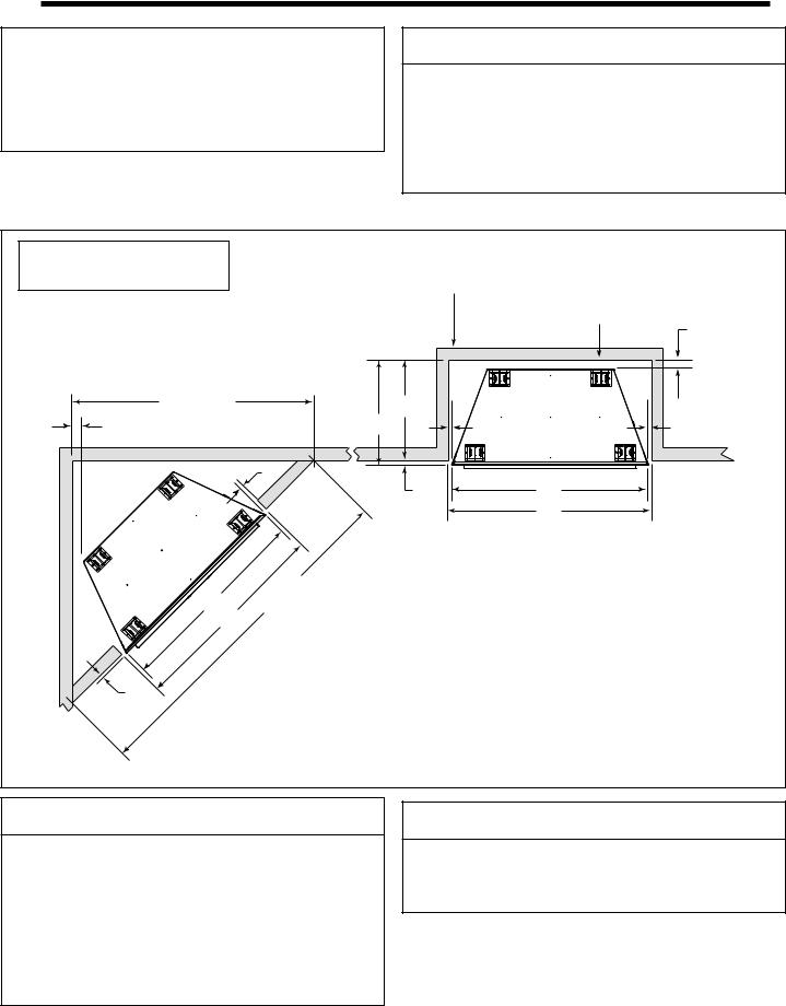
A. Select Appliance Location
When selecting a location for your appliance it is important to consider the required clearances to walls (See Figure 3.1).
 WARNING
Fire Risk
Provide adequate clearance:
•Around air openings.
•To combustibles.
•For service access.
Locate appliance away from traffic areas.
Note: For actual appliance dimensions refer to Section 13.
Note: If this surface is inside the building’s warm air envelope...
...then this surface must be an exterior wall system.
G
57-3/4 in. |
|
B |
|
(1467 mm) |
A |
|
|
G |
F |
F |
|
|
F |
|
|
|
|
E |
C |
|
|
|
D |
C |
81-3/4 in. |
(2076 mm) |
|
|
D |
|
|
A |
B |
C |
D |
E |
F |
G |
E |
in. |
24-3/4 |
24-1/8 |
48 |
49 |
5/8 |
1/2 |
1-1/2 |
|
mm |
629 |
613 |
1219 |
1245 |
16 |
13 |
38 |
Figure 3.1 Appliance Locations
 WARNING
Fire Risk
Odor Risk
•Install appliance on hard metal or wood surfaces extending full width and depth of appliance.
•Do NOT install appliance directly on carpeting, vinyl, tile or any combustible material other than wood.
 WARNING
Fire Risk
•Locate and install appliance to all clearance specifications in manual.
Heat & Glo LifeStyle Collection • Dakota 42-B/Dakota 42H-B • 4036-909 • Rev J 11/08 7

B. Clearances
|
B |
|
A |
Upper front can be |
|
covered with |
0 in. to level |
non-combustible |
|
material or removed |
of standoffs |
and replaced with |
|
non-combustible |
|
material. |
|
Object |
36 in. |
|
|
Combustible |
(914 mm) |
|
Figure 3.2 Framing Dimensions
|
|
Framing Dimensions |
|
||
|
|
A |
B |
C |
D |
|
in. |
24-1/8 |
43-7/8 |
49 |
43-7/8 |
|
mm |
613 |
1114 |
1245 |
1114 |
|
D |
|
|
|
|
|
Header height. |
|
|
|
|
C |
Use only noncombustible |
|
|
|
|
material below the top of |
|
|
|
||
|
the top standoffs. |
|
|
|
|
|
1-1/2 in. (38 mm) |
|
|
|
|
84 in. |
|
|
1-1/2 in. |
|
|
(2134 mm) |
|
|
|||
|
(38 mm) |
|
|||
to ceiling |
|
|
|||
|
|
|
|
||
|
|
|
|
1/2 in. (13 mm) |
|
|
|
|
|
Drywall |
|
0 in. |
|
|
|
0 in. |
|
Combustible flooring may be installed next |
|
|
|
||
|
|
|
|
||
|
to the front of the appliance. |
|
|
|
|
C. Mantel Projections
 WARNING
Fire Risk
•Comply with all minimum clearances to combustibles as specified.
•Framing or finishing material used on the front of, or in front of, the appliance closer than the minimums listed, must be constructed entirely of noncombustible materials (i.e., steel studs, concrete board, etc.).
Failure to comply may cause fire.
|
|
Then B |
|
If A is: |
must be at |
|
least: |
|
in. |
6 - 36 |
26 |
mm |
152 - 914 |
660 |
in. |
36 or more |
18 |
mm |
914 or more |
457 |
Roof or Overhang
12 in. (305 mm) 
 max. combustible
mantel depth
|
|
Structure |
|
|
Sidewall |
|
nal |
|
tio |
|
|
Addior |
|
|
A
Fireplace |
Structure |
|
Mantel |
||
|
84 in.
(2134 mm) minimum height
B
Figure 3.3 Clearances to Mantels or Other Combustibles Above Appliance
8 |
Heat & Glo LifeStyle Collection • Dakota 42-B/Dakota 42H-B • 4036-909 • Rev J 11/08 |
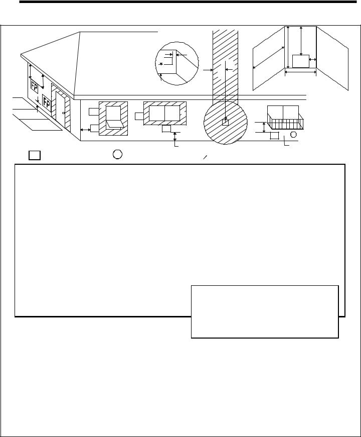
4 Termination Locations
A. Vent Termination Minimum Clearances
D
 E
E
B
L
B |
FP |
F FP |
G

 FP
FP
A
FP |
B |
|
|
|
FP |
A
FP = FIREPLACE OPENING |
X =AIR SUPPLY INLET |
|
O |
|
|
P |
|
R |
N |
|
FP |
||
|
||
H |
Q |
|
|
(See Note 2)
 I M
I M
FP
 X
X
 J or K
 =AREAWHERE FIREPLACE IS NOT PERMITTED
A |
= |
0 in. . . . . . . . . . |
clearances above grade, |
|
|
|
veranda, porch, deck or |
|
|
|
balcony. |
B |
= |
12 in. . . . . . . . . . |
clearances to window or door |
|
|
|
that may be opened, or to |
|
|
|
permanently closed window. |
|
|
36 in. . . . . . . . . . |
vinyl windows or siding. |
D** |
= |
47 in. . . . . . . . . . |
vertical clearance to unventi- |
|
|
|
lated soffit or to ventilated soffit |
|
|
|
located above the terminal. |
|
|
60 in. . . . . . . . . . |
vinyl clad soffits. |
F |
= |
9 in. . . . . . . . . . |
clearance to outside corner. |
G* |
= |
6 in. . . . . . . . . . |
clearance to inside corner. |
|
|
48 in. . . . . . . . . . |
vinyl windows or siding. |
H |
= |
3 ft. (Canada) . not to be installed above a gas |
|
|
|
|
meter/regulator assembly within |
|
|
|
3 ft (914 mm) horizontally from |
I |
= |
3 ft. (USA) |
the center line of the regulator. |
|
|||
|
|
6 ft. (Canada) . clearance to service regulator |
|
|
|
|
vent outlet and electric service. |
*48 in. minimum for vinyl windows or vinyl siding.
**Not allowed for vinyl clad soffits.
***a fireplace shall not open directly above a sidewalk or paved driveway which is located between two single family dwellings and services both dwellings.
****only permitted if veranda, porch, deck or balcony is fully open
on a minimum of 2 sides beneath the floor, or if the screened porch guidelines are followed.
Note 1: Local codes or regulations may require different clearances. Note 2: Termination in an alcove space (spaces open only on one side and with an overhang) are permitted with the dimensions specified for vinyl or non-vinyl siding and soffits. 1) There must be a 3 ft minimum between terminations or between the fireplace and termination. 2) All mechanical air intakes within 10 ft of a termination must be a minimum of 3 ft below the fireplace hood. 3) All gravity air intakes within 3 ft of the fireplace hood
must be a minimum of 1 ft below the termination.
Figure 4.1 Minimum Clearances
J |
= |
9 in. (USA) |
|
|
|
|
|
|
|
|
|
|
12 in. (Canada) . clearance to non-mechanical air |
||||||
|
|
|
|
supply inlet to building or the |
|||||
|
|
|
|
combustion air inlet to any other |
|||||
K |
= |
3 ft. (USA) |
appliance. |
|
|
|
|||
|
|
|
|
|
|
||||
|
|
|
6 ft. (Canada) . clearance to a mechanical air |
||||||
|
|
|
|
supply inlet. |
|
|
|
||
L*** |
= |
54 in. . . . . . . . . . clearance above paved sidewalk |
|||||||
|
|
(See note 1) |
or a paved driveway located on |
||||||
|
|
|
|
public property. |
|
|
|
||
M****= |
47 in. . . . . . . . . . clearance under veranda, porch, |
||||||||
|
|
|
|
deck, balcony or overhang. |
|||||
|
|
Not allowed: . . . . . . vinyl |
|
|
|
|
|||
N |
= |
6 in. . . . . . . . . . non-vinyl siding. |
|
|
|
||||
P |
= |
84 in. |
|
|
|
|
|
|
|
|
|
|
|
|
|
QMIN |
|
RMAX |
|
|
|
|
|
|
|
|
|||
|
Dakota |
|
|
10 feet |
|
2 x Q ACTUAL |
|||
|
1 additional termination cap |
|
Q + 3 feet |
|
1 x Q ACTUAL |
||||
|
2 additional termination caps |
|
Q + 6 feet |
|
2/3 x Q ACTUAL |
||||
|
3 additional termination caps |
|
Q + 9 feet |
|
1/2 x Q ACTUAL |
|
|||
RMAX = (2 / # caps plus fireplace ) x QACTUAL
This fireplace is approved for installation onto screen porches with the following guidelines:
Minimum porch area: 96 sq ft
Minimum ceiling height: 84 in.
Minimum of two walls must be screened
Minimum top of screen height, side walls: 6 ft 8 in.
Minimum screen area: 64 sq ft
Note 2: There may be some odor and small amounts of soot associated with burning the Dakota on a screened porch. Ensuring good cross draft ventilation and routine maintenance of the fireplace will maximize comfort and cleanliness.
Heat & Glo LifeStyle Collection • Dakota 42-B/Dakota 42H-B • 4036-909 • Rev J 11/08 9
5 Appliance Preparation
|
CAUTION |
B. Securing and Leveling Appliance |
|
|
WARNING |
||
Sharp Edges |
|||
• |
Wear protective gloves |
Fire Risk |
|
|
and safety glasses during |
• Prevent contact with sagging, loose |
|
|
installation. |
insulation. |
|
|
|
• Do NOT install against vapor barriers or |
|
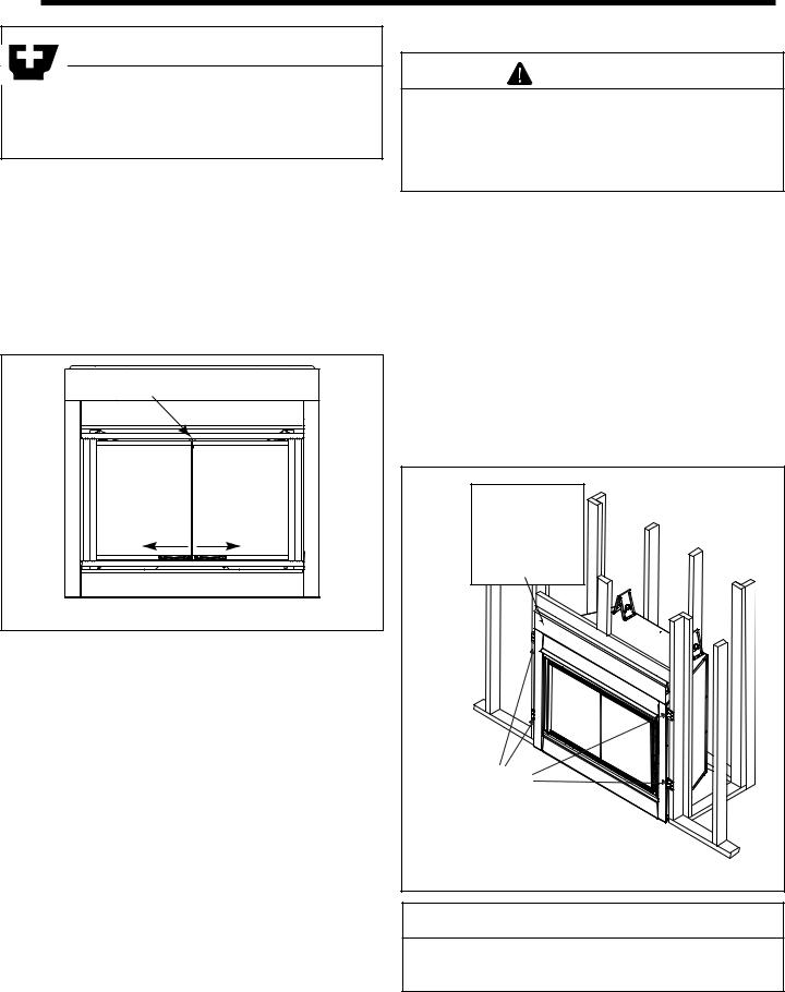
A. Remove Logs and Shipping Cover |
exposed insulation. |
||
The diagram shows how to properly position, level, and se- |
|||
Remove locking screw at the top of the doors (shown in Fig- |
|||
cure the appliance (see Figure 5.2). Nailing tabs are pro- |
|||
ure 5.1). |
|
||
|
vided to secure the appliance to the framing members. |
||
Open the doors by sliding the handles toward the outside |
|||
• Place the appliance into position on either a combustible |
|||
edges of the doors. Remove the cartons of logs from their |
|||
or non-combustible continuous flat surface. |
|||
shipping location in the appliance. |
|||
Note: Remove the top standoffs before sliding appliance |
|||
Set the logs and door lock bracket screw aside for later re- |
|||
into position if using an FPS prefab enclosure. |
|||
installation. |
|
• Level the appliance from side to side and front to back. |
|
|
|
||
|
|
• Shim the appliance with non-combustible material, such |
|
|
Locking Screw |
as sheet metal, as necessary. |
|
|
• Bend out nailing tabs on each side. |
||
|
|
• Keep nailing tabs flush with the framing. |
|
|
|
• Secure the appliance to the framing by using nails or |
|
|
|
screws through the nailing tabs. |
|
|
|
Upper front can be |
|
|
|
covered with |
|
|
Open Open |
non-combustible |
|
|
material or removed |
||
|
|
and replaced with |
|
|
|
non-combustible |
|
|
|
material. |
|
Figure 5.1 |
Door Operation |
|
|
NAILING TABS
Figure 5.2 Proper Positioning, Leveling and Securing of an
Appliance
CAUTION
Do NOT notch into the framing around the appliance spacers.
10 |
Heat & Glo LifeStyle Collection • Dakota 42-B/Dakota 42H-B • 4036-909 • Rev J 11/08 |
6 Gas Information
A. Fuel Conversion |
C. Gas Connection |
Before making gas connections ensure appliance being installed is compatible with the available gas type.
Any natural or propane gas conversions necessary to meet the appliance and locality needs must be made by a qualified technician using Hearth & Home Technologies specified and approved parts.
Note: Have the gas supply line installed in accordance with local building codes, if any. If not, follow ANSI 223.1. Installation should be done by a qualified installer approved and/or licensed as required by the locality. (In the Commonwealth of Massachusetts installation must be performed by a licensed plumber or gas fitter.)
B. Gas Pressure
Proper input pressures are required for optimum appliance performance. Gas line sizing requirements need to be made following NFPA51.
 WARNING
Fire Risk
Explosion Risk
High pressure will damage valve.
•Disconnect gas supply piping BEFORE pressure testing gas line at test pressures above 1/2 psig.
•Close the manual shutoff valve BEFORE pressure testing gas line at test pressures equal to or less than 1/2 psig.
Note: A listed (and Commonwealth of Massachusetts approved) 1/2 in. (13 mm) T-handle manual shut-off valve and flexible gas connector are connected to the 1/2 in. (13 mm) control valve inlet.
•If substituting for these components, please consult local codes for compliance.
Optional: A 5 ft flexible gas line is available to those regions which do not require black pipe to be used. See Service Parts List (Section 13).
Note: Gas line MUST be run from right side of appliance.
 WARNING
Fire Risk
Explosion Risk
Verify inlet pressures.
•High pressure may cause overfire condition.
•Low pressure may cause explosion.
Install regulator upstream of valve if line pressure is greater than 1/2 psig.
Pressure requirements for |
appliance are shown in table |
||||
below. |
|
|
|
||
|
|
|
|
|
|
|
Pressure |
|
Natural Gas |
Propane |
|
|
Minimum Inlet Pressure |
|
5.0 inches w.c. |
11.0 inches w.c. |
|
|
Maximum Inlet Pressure |
|
7.0 inches w.c. |
14.0 inches w.c. |
|
|
|
|
|
|
|
|
Manifold Pressure |
|
3.5 inches w.c. |
10.5 inches w.c. |
|
These pressures can be verified through the internal valve access panels as shown in Section E. Valve Access.
 WARNING
Gas Leak Risk
•Support control when attaching pipe to prevent bending gas line.
Note: The gap between supply piping and gas access hole may be plugged with non-combustible unfaced insulation to prevent cold air infiltration.
•Ensure that gas line does not come in contact with outer wrap of appliance. Follow local codes.
•Incoming gas line should be piped into the valve compartment and connected to the 1/2 in. connection on the manual shutoff valve.
Heat & Glo LifeStyle Collection • Dakota 42-B/Dakota 42H-B • 4036-909 • Rev J 11/08 11
 Loading...