


hatcocorp.com
Reg ine!
ine!
(see page 2)
S'inscrire en ligne!
 Slim(voir page 16) Refrigerated Drop-In Wells Cuves réfrigérées allongées libre-service
CWB-S Series • Série CWB-S
Installation and Operating Manual Manuel d'installation et d'utilisation
WARNING
Do not operate this equipment unless you have read and understood the contents of this manual! Failure to follow the instructions contained in this manual may result in serious injury or death. This manual contains important safety information concerning the maintenance, use, and operation of this product. If you’re unable to understand the contents of this manual, please bring it to the attention of your supervisor. Keep this manual in a safe location for future reference.
P/N 07.04.774.00
ADVERTENCIA
No opere este equipo al menos que haya leído y comprendido el contenido de este manual! Cualquier falla en el seguimiento de las instrucciones contenidas en este manual puede resultar en un serio lesión o muerte. Este manual contiene importante información sobre seguridad concerniente al mantenimiento, uso y operación de este producto. Si usted no puede entender el contenido de este manual por favor pregunte a su supervisor. Almacenar este manual en una localización segura para la referencia futura.
AVERTISSEMENT
Ne pas utiliser cet équipement sans avoir lu et compris le contenu de ce manuel ! Le non-respect des instructions contenues dans ce manuel peut entraîner de graves blessures ou la mort. Ce manuel contient des informations importantes concernant l'entretien, l'utilisation et le fonctionnement de ce produit. Si vous ne comprenez pas le contenu de ce manuel, veuillez le signaler à votre supérieur. Conservez ce manuel dans un endroit sûr pour pouvoir vous y référer plus tard.
Français = p 16
© 2016 Hatco Corporation
CONTENTS |
|
English |
Important Owner Information .............................................. |
2 |
Introduction........................................................................... |
2 |
Important Safety Information............................................... |
3 |
Model Description................................................................. |
4 |
Model Designation................................................................ |
5 |
Specifications........................................................................ |
5 |
Plug Configuration ............................................................... |
5 |
Electrical Rating Chart ......................................................... |
5 |
Refrigerant Information ........................................................ |
5 |
Dimensions .......................................................................... |
6 |
Installation ............................................................................. |
7 |
General ................................................................................ |
7 |
Preparing the Unit for Installation ........................................ |
7 |
Preparing the Installation Site.............................................. |
8 |
Installing the Unit ................................................................. |
8 |
Countertop Cutout Dimensions............................................ |
9 |
Operation............................................................................. |
10 |
General .............................................................................. |
10 |
Changing the Setpoint Temperature .................................. |
11 |
Setting the auto-Defrost Cycle........................................... |
11 |
Maintenance ........................................................................ |
12 |
General .............................................................................. |
12 |
Daily Cleaning.................................................................... |
12 |
monthly Cleaning ............................................................... |
12 |
Troubleshooting Guide ...................................................... |
13 |
Options and Accessories................................................... |
14 |
Limited Warranty................................................................. |
15 |
Authorized Parts Distributors............................ |
Back Cover |
IMPORTANT OWNER INFORMATION
Record the model number, serial number, voltage, and purchase date of the unit in the spaces below (specification label located on bottom of unit and back of control panel). Please have this information available when calling Hatco for service assistance.
model No. ________________________________________
Serial No. ________________________________________
Voltage __________________________________________
Date of Purchase __________________________________
Register your unit!
Completing online warranty registration will prevent delay in obtaining warranty coverage. access the Hatco website at www.hatcocorp.com, select the Parts & Service pull-down menu, and click on “Warranty Registration”.
7:00 am to 5:00 Pm Central Standard Time (CST) (Summer Hours: June to September—
7:00 am to 5:00 Pm CST monday–Thursday 7:00 am to 4:00 Pm CST Friday)
Telephone: 800-558-0607; 414-671-6350 e-mail: partsandservice@hatcocorp.com
24 Hour 7 Day Parts and Service
Assistance available in the United States and Canada by calling 800-558-0607.
additional information can be found by visiting our web site at www.hatcocorp.com.
INTRODUCTION
Hatco Slim Refrigerated Drop-In Wells are specially designed to hold cold foods at safe serving temperatures while providing easy, reachable access to all items in the well. The insulated, top-mount units are available in one through four pan configurations. a unique top bezel design allows cold air to effectively blanket the food product inside the refrigerated well. In addition, the bezel design provides clear viewing and easy access to the food contents of the refrigerated well.
all models are equipped with a condensing unit that can be rotated to accommodate the installation location. The condensing units on the two, three, and four pan models also can be moved between the center of the unit and the evaporator coil connection for additional installation flexibility.
Hatco Slim Refrigerated Drop-In Wells are a product of extensive research and field testing. The materials used were selected for maximum durability, attractive appearance, and optimum performance. Every unit is inspected and tested thoroughly prior to shipment.
This manual provides the installation, safety, and operating instructions for the Slim Refrigerated Drop-In Wells. Hatco recommends all installation, operating, and safety instructions appearing in this manual be read prior to installation or operation of a unit.
Safety information that appears in this manual is identified by the following signal word panels:
WARNING
WARNING indicates a hazardous situation which, if not avoided, could result in death or serious injury.
CAUTION
CAUTION indicates a hazardous situation which, if not avoided, could result in minor or moderate injury.
NOTICE
NOTICE is used to address practices not related to personal injury.
2 |
Form No. CWBSm-0616 |
|
|
IMPORTANT SAFETy INFORMATION |
English |
Read the following important safety information before using this equipment to avoid serious injury or death and to avoid damage to equipment or property.
WARNING
ELECTRIC SHOCK HAzARD:
• Plug unit into a properly grounded electrical receptacle of the correct voltage, size, and plug configuration. If plug and receptacle do not match, contact a qualified electrician to determine and install proper voltage and size electrical receptacle.
• Turn OFF power switch and disconnect unit from power source before performing any cleaning, adjustments, or maintenance.
• Unit is not weatherproof. Locate unit indoors.
• DO NOT submerge or saturate with water. Unit is not waterproof. Do not operate if unit has been submerged or saturated with water.
• This unit is not “jet-proof” construction. Do not use jetclean spray to clean this unit.
• Discontinue use if power cord is frayed or worn.
• Do not attempt to repair or replace a damaged power cord. The cord must be replaced by Hatco, an Authorized Hatco Service Agent, or a person with similar qualifications.
• This unit must be serviced by qualified personnel only. Service by unqualified personnel may lead to electric shock or burn.
• Use only Genuine Hatco Replacement Parts when |
|
||
service is required. Failure to use Genuine Hatco |
|
||
Replacement Parts will void all warranties and may |
|
||
subject operators of the equipment to hazardous |
|
||
electrical voltage, resulting in electrical shock or burn. |
|
||
Genuine Hatco Replacement Parts are specified to |
|
||
operate safely in the environments in which they are |
|
||
used. Some aftermarket or generic replacement parts |
|
||
do not have the characteristics that will allow them to |
|
||
operate safely in Hatco equipment. |
|
||
|
|
|
|
FIRE HAzARD: |
|
||
• Install unit with a minimum of 2″ (51 mm) of space |
|
||
between all sides of condensing unit and any |
|
||
combustible surfaces. |
|
||
• Do not use flammable cleaning solutions to clean this unit. |
|
||
ExPLOSION HAzARD: Do not store or use gasoline or |
|
||
other flammable vapors or liquids in the vicinity of this or |
|
||
any other appliance. |
|
||
This unit must be installed by qualified, trained installers. |
|
||
Installation must conform to all local electrical and |
|
||
plumbing codes. Check with local plumbing and electrical |
|
||
inspectors for proper procedures and codes. |
|
||
Make sure food product has been chilled to the proper |
|
||
food-safe temperature before placing in the unit. Failure to |
|
||
chill food product properly may result in serious health |
|
||
risks. This unit is for holding pre-chilled food product only. |
|
||
Hatco Corporation is not responsible for actual food |
|
||
product serving temperature. It is the responsibility of the |
|
||
user to ensure that food product is held and served at a |
|
||
safe temperature. |
|
||
Make sure all operators have been instructed on the safe |
|
||
and proper use of the unit. |
|
||
Form No. CWBSm-0616 |
3 |
||
|
|
|
|
WARNING
This unit is not intended for use by children or persons with reduced physical, sensory, or mental capabilities. Ensure proper supervision of children and keep them away from the unit.
Maintain proper cleanliness of the unit. Proper cleanliness and sanitation is critical for food-safe operation. Refer to the MAINTENANCE section for cleaning procedures.
This unit has no “user-serviceable” parts. If service is required on this unit, contact an Authorized Hatco Service Agent or contact the Hatco Service Department at 800-558-0607 or 414-671-6350.
CAUTION
Locate unit at the proper counter height in an area that is convenient for use. Location should be level and strong enough to support weight of unit and contents.
NOTICE
This unit is designed for use in environments where ambient temperature is between 65°F (18°C) and 86°F (30°C).
When shipped during cold weather months, store unit in proper ambient temperature environment for 10 hours to prevent compressor and/or refrigerant line damage. If unit is turned on and there is excessive noise and vibration, turn off immediately and allow additional warm up time.
Provide louvered or grill-style openings with a minimum size of 12" x 12"/144 square inches (31 x 31 cm/ 961 square cm) in the cabinetry in front of and behind the condensing unit for proper ventilation. Failure to provide adequate air flow through the condensing unit may cause unit failure and will void the unit warranty.
Do not recirculate exhaust air inside cabinet when multiple refrigerated wells are installed together. Intake air should enter from outside of cabinet.
Transport and install unit in upright position only. Failure to do so may result in damage to refrigeration system. Use caution and avoid hitting condensing unit hoses/lines when installing unit. Damage caused during installation is not covered under warranty.
Do not locate unit in an area subject to excessive temperatures or grease from grills, fryers, etc. Excessive temperatures could cause damage to the unit.
Clean unit daily to avoid malfunctions and maintain sanitary operation.
Use non-abrasive cleaners and cloths only. Abrasive cleaners and cloths could scratch finish of unit, marring its appearance and making it susceptible to soil accumulation. Do not use steel wool for cleaning. Steel wool will scratch the finish.
Do not use harsh chemicals such as bleach, cleaners containing bleach, or oven cleaners to clean the unit. This unit is intended for commercial use only—NOT for household use.
MODEL DESCRIPTION |
|
|
|
|
||
|
|
English |
||||
|
|
|
|
|
|
|
All Models |
|
|
The ecoization logo identifies products designed to reflect |
|||
Hatco Slim Refrigerated |
Drop-In Wells are reliable |
and |
Hatco’s commitment to improving, protecting, and preserving |
|||
the global environment. Hatco Slim Refrigerated Drop-In Wells |
||||||
versatile. Each unit has |
an insulated, stainless steel |
and |
||||
qualify for the ecoization logo through the use of green-friendly |
||||||
aluminized steel housing. The sides of the internal well are |
||||||
insulation as well as a highly efficient condensing unit. |
||||||
completely surrounded with a copper evaporator coil to provide |
||||||
|
|
|
||||
even chilling from top to bottom. The Slim Refrigerated Drop-In |
Each model of Slim Refrigerated Drop-In Well is supplied from |
|||||
Well is controlled with a digital temperature controller and a |
the factory with the appropriate number of 12″ (305 mm) Pan |
|||||
Power I/O (on/off) Switch housed in a single, remote-mountable |
Support Bars, depending on the model’s pan capacity. |
|||||
control panel. The control panel is connected to the condensing |
Each individual well is capable of holding a variety of pan |
|||||
unit with a 48″ (1219 mm) power cord. a 6′ (1829 mm) power |
||||||
combinations of full size, 1/2-size, 1/3-size, and/or 1/6-size pans |
||||||
cord and plug connected to the control panel provides power to |
||||||
with accessory adapter Bars. |
||||||
the entire unit. |
|
|
||||
|
|
|
|
|
||
all models are designed to be mounted to the topside of various |
Food Pans, Pan Support Bars, adapter Bars, and other |
|||||
accessories are available for the Slim Refrigerated Drop-In |
||||||
types of countertop material including stainless steel, wood, |
||||||
Wells. Refer to the OPTIONS aND aCCESSORIES section in |
||||||
Corian, Swanstone, etc... Hatco Slim Refrigerated Drop-In |
||||||
this manual for details. |
||||||
Wells are designed, manufactured, and tested to maintain safe |
||||||
food holding temperatures. |
|
|
|
|
||
CWB-S1 |
CWB-S2 |
CWB-S3 |
CWB-S4 |
Pans Not Included
4 |
Form No. CWBSm-0616 |
|
|
|
|
|
|
|
|
|
|
|
|
|
|
|
|
MODEL DESIGNATION |
English |
|||||||||||||||
|
|
|
|
|
|
|
|
|
|
|
|
|
|
|
|
|
Cold Well |
C W B - S X |
|||||||||||||
|
|
|
|
|
|
|
|
|
|
|
|
|
|
Full-Size Pan Capacity |
|
|
|
|
|
|
|
|
|
|
|
|
|
|
|
||
|
Built-In |
|
|
|
|
|
|
|
|
|
|
|
|
|
Slim |
|
|
|
|
|
|
|
|
|
|
|
|
|
|
||
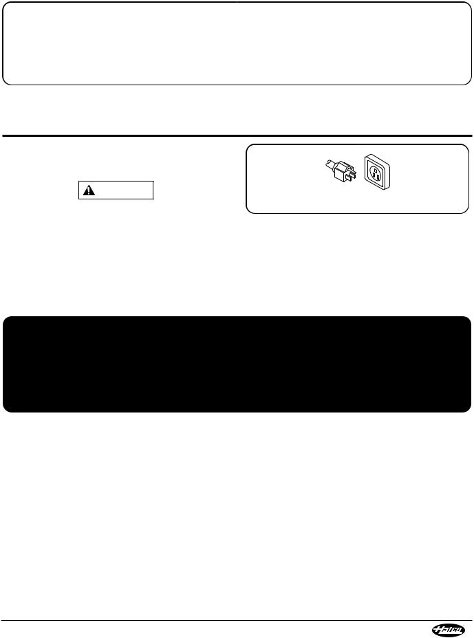
Plug Configuration
SPECIFICATIONS
Units are supplied from the factory with an electrical cord and plug installed. Plugs are supplied according to the application.
WARNING
ELECTRIC SHOCK HAzARD: Plug unit into a properly grounded electrical receptacle of the correct voltage, size, and plug configuration. If plug and receptacle do not match, contact a qualified electrician to determine and install proper voltage and size electrical receptacle.
NOTE: Receptacle not supplied by Hatco.
NEMA 5-15P
Plug Configuration
Electrical Rating Chart |
|
|
Model |
Compressor |
Voltage |
Size |
||
CWB-S1 |
1/4 hp |
120 |
CWB-S2 |
1/4 hp |
120 |
CWB-S3 |
1/3 hp |
120 |
CWB-S4 |
1/2 hp |
120 |
NOTE: Shipping weight includes packaging.
Watts |
Amps |
Plug |
Shipping |
Configuration |
Weight |
||
804 |
6.7 |
NEma 5-15P |
133 lbs. (60 kg) |
804 |
6.7 |
NEma 5-15P |
175 lbs. (79 kg) |
1044 |
8.7 |
NEma 5-15P |
213 lbs. (97 kg) |
1380 |
11.5 |
NEma 5-15P |
235 lbs. (107 kg) |
NOTE: The specification labels are located on the bottom of the unit and the back of the control panel. See the label for the serial number and verification of unit electrical information.
Refrigerant Information
all Hatco Slim Refrigerated Drop-In Wells use R-404a refrigerant in the condensing unit.
Form No. CWBSm-0616 |
5 |
|

SPECIFICATIONS |
|
|
|
|
|
||
|
|
|
English |
||||
|
|
|
|
|
|
|
|
Dimensions |
Width |
Depth |
Overall Height |
Well Height |
|||
Model |
(A) |
(B) |
(C) * |
(D) |
|||
CWB-S1 |
27-1/16″ |
18-15/16″ |
25-1/16″ |
12-1/16″ |
|||
(687 mm) |
(481 mm) |
(636 mm) |
(306 mm) |
||||
|
|||||||
CWB-S2 |
48-1/8″ |
18-15/16″ |
25-1/16″ |
12-1/16″ |
|||
(1222 mm) |
(481 mm) |
(636 mm) |
(306 mm) |
||||
|
|||||||
CWB-S3 |
68-3/16″ |
18-15/16″ |
25-1/16″ |
12-1/16″ |
|||
(1757 mm) |
(481 mm) |
(636 mm) |
(306 mm) |
||||
|
|||||||
CWB-S4 |
90-1/4″ |
18-15/16″ |
25-1/16″ |
12-1/16″ |
|||
(2292 mm) |
(481 mm) |
(636 mm) |
(306 mm) |
||||
|
|||||||
* add 7-5/8″ (193 mm) to Overall Height (C) when control box is installed on bottom of condensing unit (CWB-S1 model only).
A
2-3/4″ (70 mm)
Front View
(Model CWB-S4)
17-3/8″ |
9-1/8″ |
(441 mm) |
(232 mm) |
B |
|
|
D |
Side View |
C |
(Model CWB-S4) |
|
15-7/16″
(392 mm)
17″ (430 mm)
6 |
Form No. CWBSm-0616 |
|
|
English |
|
|
INSTALLATION |
|
General |
|
Preparing the Unit for Installation |
|||
Refrigerated Slim Drop-In Wells are shipped from the factory |
The orientation of the condensing unit on all CWB-S models can |
||||
completely assembled and ready for use. Use the following |
be adjusted to match the layout of the installation site. It can be |
||||
information and procedures to prepare the unit and installation |
rotated 90° or 180° from its factory-installed position. On |
||||
site. |
|
CWB-S2, -S3, and -S4 models, the condensing unit also can be |
|||
|
|
|
mounted in several positions between the center of the well and |
||
|
WARNING |
|
the evaporator coil connections. Rotating the condensing unit |
||
|
|
must be performed after installing the unit due to the dimension |
|||
ELECTRIC SHOCK HAzARD: |
|
of the countertop cutout. |
|
||
• |
Plug unit into a properly grounded electrical receptacle |
Survey the installation site and determine if adjustment to the |
|||
|
of the correct voltage, size, and plug configuration. If |
||||
|
orientation and/or position of the condensing unit is necessary. |
||||
|
plug and receptacle do not match, contact a qualified |
||||
|
Take into account the need for louvered or grill-style openings in |
||||
|
electrician to determine and install proper voltage and |
||||
|
the cabinetry to provide proper ventilation for the unit as well as |
||||
|
size electrical receptacle. |
|
|||
|
|
access to the control panel. One of these ventilation openings |
|||
• |
Unit is not weatherproof. Locate unit indoors. |
|
|||
|
must be in front of the condensing coils with the other on the |
||||
FIRE HAzARD: Install unit with a minimum of 2″ (51 mm) of |
opposite side. If multiple refrigerated wells are installed in the |
||||
same counter, each unit should intake cool air and expel hot air. |
|||||
space between all sides of condensing unit and any |
If adjustment to the orientation of the condensing unit is |
||||
combustible surfaces. |
|
||||
This unit must be installed by qualified, trained installers. |
necessary, use the “Rotating the Condensing Unit” procedure |
||||
after installing the unit. If adjustment to the position of the |
|||||
Installation must conform to all local electrical and |
condensing unit is necessary, use the following procedure. |
||||
plumbing codes. Check with local plumbing and electrical |
Moving the Condensing Unit |
||||
inspectors for proper procedures and codes. |
|
||||
|
This procedure can be performed on CWB-S2, CWB-S3, and |
||||
|
|
|
|||
|
CAUTION |
|
CWB-S4 models only. |
|
|
|
|
1. Remove the two control panel bolts that secure the control |
|||
Locate unit at the proper counter height in an area that is |
panel to the condensing unit support frame. Set aside the |
||||
convenient for use. Location should be level and strong |
control panel. |
|
|||
enough to support weight of unit and contents. |
|
2. Remove the four mounting screws that secure the condensing |
|||
|
NOTICE |
|
unit support frame to the underside of the well enclosure. |
||
|
|
3. move the condensing unit to the desired position. The |
|||
Transport and install unit in upright position only. Failure |
condensing unit can be installed in several positions using |
||||
to do so may result in damage to refrigeration system. |
pre-drilled holes at 6-1/2" (165 mm) increments between |
||||
This unit is designed for use in environments where ambient |
the center of the unit and the evaporator coil connections. |
||||
4. Reattach the condensing unit support frame to the well |
|||||
temperature is between 65°F (18°C) and 86°F (30°C). |
|
||||
|
enclosure using the four mounting screws. |
||||
When shipped during cold weather months, store unit in |
|||||
5. Reattach the control panel to the condensing unit support |
|||||
proper ambient temperature environment for 10 hours to |
|||||
frame using the two control panel bolts. |
|||||
prevent compressor and/or refrigerant line damage. If unit is |
|||||
|
|
||||
turned on and there is excessive noise and vibration, turn |
Condensing Unit in End Position |
||||
off immediately and allow additional warm up time. |
|
||||
|
|
|
|||
Provide louvered or grill-style openings with a minimum |
|
|
|||
size of 12" x 12"/144 square inches (31 x 31 |
cm/ |
|
|
||
961 square cm) in the cabinetry in front of and behind the |
|
|
|||
condensing unit for proper ventilation. Failure to provide |
|
|
|||
adequate air flow through the condensing unit may cause |
Mounting |
|
|||
unit failure and will void the unit warranty. |
|
Screw |
Control Panel Bolt |
||
Do not locate unit in an area subject to excessive |
|
||||
|
|
||||
temperatures or grease from grills, fryers, etc. Excessive |
Condensing Unit Moved to Center Position |
||||
temperatures could cause damage to the unit. |
|
||||
|
|
|
|||
all Slim Refrigerated Drop-In Wells are shipped in a wooden |
|
|
|||
frame for protection and stability. Keep the unit in the wooden |
|
|
|||
frame until the unit and the installation site are completely |
|
|
|||
prepared for the unit to be installed. |
|
|
|
||
1. Remove all external packaging from the unit. |
|
|
|
||
2. Remove tape, protective packaging, and literature from all |
|
|
|||
|
surfaces of the unit. |
|
moving a CWB-S4 model Condensing Unit |
||
NOTE: To prevent delay in obtaining warranty coverage, |
|||||
|
|
||||
|
complete online warranty registration. See |
the |
|
|
|
|
ImPORTaNT OWNER INFORmaTION section for details. |
|
|
||
Form No. CWBSm-0616 |
7 |
|
INSTALLATION
Preparing the Installation Site
1. Cut the appropriate opening in the countertop for the unit being installed. Refer to “Countertop Cutout Dimensions” in this section.
2. If installing the control panel remotely, cut and drill the appropriate holes in the vertical surface where the control panel will be installed. Refer to the “Installing the Control Panel Remotely” procedure for cutout dimensions.
3. make structural modifications or add bracing underneath the countertop to ensure the countertop will support the weight of the unit and its contents. make sure a minimum 2" (51 mm) clearance will be available between the condensing unit and any interior surface.
NOTE: The countertop must be level to ensure proper draining of the refrigerated well.
4. Cut two openings in the cabinetry to provide proper ventilation to the condensing unit as well as access to the control panel. Louvered or grill-style panels should be installed in the openings to protect the condensing unit.
• Openings should be a minimum of 12" x 12" (31 x 31 cm) or 144 square inches (961 square cm).
• One opening should be located in front of the condenser coils with the other opening on the opposite side.
5. make sure a grounded electrical receptacle of the correct voltage, size, and plug configuration is within 6′ (1829 mm) of the mounting location for the control panel. See the SPECIFICaTIONS section for details.
Installing the Unit
NOTICE
Use caution and avoid hitting condensing unit hoses/lines when installing unit. Damage caused during installation is not covered under warranty.
1. Lift the unit out of the wooden shipping frame and carefully lower it into the countertop cutout.This step requires two or more people, depending on the unit.
2. apply National Sanitation Foundation-approved (NSFapproved) silicone sealant around the edge of the unit to seal it to the countertop.
3. Install the control panel in the desired location.
• The control panel can be installed on one of three sides of the condensing unit support frame. Do not install the control panel in front of the condenser coils.
• The control panel can be installed remotely within 48″ (1219 mm) of the condensing unit. Refer to the “Installing the Control Panel Remotely” procedure in this section.
4. Connect the 1" drain fitting to a trap and drain line. If a trap and drain line are not available, a catch pan (not supplied) must be used under the drain fitting to contain water draining from the well enclosure.
NOTE: Consult a qualified plumber for proper trap and drain installation that conforms to local plumbing codes.
English
ountertop utout
|
Air F |
lo |
|
|
|
V n |
|
Contr |
Accessboth sides |
||
|
tilation/ |
|
|
Opening |
|
|
(on |
|
|
of cabinet) |
|
Installing a CWB-S2 model
5. Clean the well enclosure thoroughly in preparation for initial operation. Refer to the maINTENaNCE section for proper cleaning procedures.
NOTE: If a catch pan is used underneath the drain fitting, make sure the pan is emptied regularly to prevent over-flowing.
6. Rotate the condensing unit, if necessary. Refer to the “Rotating the Condensing Unit” in this section.
7. Plug the unit into a properly grounded electrical receptacle of the correct voltage, size, and plug configuration. See the SPECIFICaTIONS section for details.
Rotating the Condensing Unit
1. Remove the two control panel bolts that secure the control panel to the condensing unit support frame. Set aside the control panel.
2. Place blocks underneath the condensing unit for support during rotation.
3. Remove the 16 support bolts (four on each support) that secure the condensing unit vertical supports to the upper support brackets on the underside of the well enclosure.
4. Rotate the condensing unit 90° or 180°, depending on the installation site.
NOTE: Do not rotate the condensing unit in a direction that will put the evaporator lines or any other obstruction in front of the condenser coil.
5. Reattach the vertical supports to the upper support brackets on the well enclosure using the 16 support bolts.
6. Reattach the control panel to the condensing unit support frame using the two control panel bolts.
8 |
Form No. CWBSm-0616 |
|
English |
INSTALLATION |
Control Panel |
|
Upper |
Vertical |
Support |
|
Support |
Bolt |
Bracket |
|
Control |
|
Panel Bolt |
|
Vertical |
|
Support |
|
Installing the Control Panel Remotely
Use the following procedure to install the control panel remotely.
WARNING
Control panel must be mounted in a vertical surface. Mounting control panel in a horizontal surface may result in the collection of liquids and lead to electric shock.
1. Remove the four trim cover screws from the control panel, and remove the trim cover.
2. Position the control panel into the cutout opening through the backside.
3. Fasten the control panel to the vertical surface using four screws (not supplied).
4. Reinstall the trim cover on the control panel and secure in position using the four trim cover screws. Seal the trim cover to the mounting surface with silicone adhesive.
Condensing Unit rotated 90°.
Hoses removed for clarity.
Rotating the Condensing Unit
Countertop Cutout Dimensions |
||||
|
Width |
|
Depth |
|
Model |
(A) |
|
(B) |
|
CWB-S1 |
25-3/16″–26-1/16″ 17-1/16″–17-15/16″ |
|||
(641–662 mm) |
|
(433–456 mm) |
||
|
|
|||
CWB-S2 |
46-1/4″–47-1/8″ |
17-1/16″–17-15/16″ |
||
(1175–1196 mm) |
|
(433–456 mm) |
||
|
|
|||
CWB-S3 |
67-5/16″–68-1/8″ |
17-1/16″–17-15/16″ |
||
(1710–1731 mm) |
(433–456 mm) |
|||
|
||||
CWB-S4 |
88-3/8″–89-3/16″ |
17-1/16″–17-15/16″ |
||
(2245–2266 mm) |
(433–456 mm) |
|||
|
||||
|
|
|
|
|
1-1/16″
(27 mm)
5-5/8″
(143 mm) 3-1/2″
(89 mm)
7-7/16″
(189 mm)
7-3/4″
(196 mm)
Control Panel Cutout Dimensions
NOTE: Make sure the width of the control panel cutout does not exceed the above dimension.
B
|
A |
|
CWB-S Series Countertop Cutout Dimensions |
|
|
Form No. CWBSm-0616 |
9 |
|
OPERATION |
|
English |
Use the following procedures to operate the Slim Refrigerated |
Symbol |
Controller |
General |
Unit “Active” |
Digital Temperature |
Drop-In Wells. |
|
|
WARNING
Read all safety messages in the Important Safety Information section before operating this equipment. Make sure food product has been chilled to the proper food-safe temperature before placing in the unit. Failure to chill food product properly may result in serious health risks. This unit is for holding pre-chilled food product only.
|
|
NOTICE |
|
|
|
|
|
|
|
This unit is designed for use in environments where ambient |
|
|
|
|
|
||||
temperature is between 65°F (18°C) and 86°F (30°C). |
|
|
|
|
|
||||
When shipped during cold weather months, store unit in |
|
|
|
|
|
||||
proper ambient temperature environment for 10 hours to |
|
|
|
|
|
||||
prevent compressor and/or refrigerant line damage. If unit is |
|
|
|
|
|
||||
turned on and there is excessive noise and vibration, turn off |
Power I/O(On/Off) Switch |
|
|||||||
immediately and allow additional warm up time. |
|
||||||||
|
|
|
|
|
|||||
Startup |
|
|
|
|
CWB-S Series Control Panel |
|
|||
1. Fill the refrigerated well with empty food pans. The well will |
Shutdown |
|
|
|
|
||||
chill to the setpoint temperature more quickly and efficiently |
1. move the Power I/O (on/off) Switch to the “O” (off) position. |
||||||||
with empty pans in the well. |
|||||||||
The digital temperature controller and condensing unit will |
|||||||||
2. move the Power I/O (on/off) Switch to the “I” (on) position |
|||||||||
shut off. |
|
|
|
|
|||||
(located on the control panel). |
2. Perform the “Daily Cleaning” procedure |
in the |
|||||||
• The digital temperature controller will energize and “ON” |
|||||||||
maINTENaNCE section of this manual. |
|
||||||||
will appear on the display, followed by the current |
|
|
|
|
|
||||
temperature of the unit. |
|
|
NOTICE |
|
|
||||
• The |
symbol on the display will illuminate to show |
|
|
|
|
|
|||
Clean unit daily to avoid malfunctions and |
maintain |
||||||||
the c |
ensing unit is active and chilling the well. |
||||||||
sanitary operation. |
|
||||||||
NOTE: The |
unit is pre-set at the factory to a setpoint |
|
|||||||
NOTE: If a catch pan is used underneath the drain fitting, make |
|||||||||
temperature of 32°F (0°C). If ambient conditions require |
|||||||||
sure the pan is emptied regularly to prevent over- |
|||||||||
adjustment to the setpoint temperature, refer to the |
|||||||||
flowing. |
|
|
|
|
|||||
“Changing the Setpoint Temperature” in this section. |
|
|
|
|
|||||
|
|
|
|
|
|||||
3. allow the unit approximately 60 minutes to reach the |
|
|
|
|
|
||||
setpoint temperature before loading pre-chilled food |
|
|
|
|
|
||||
product. |
|
|
|
|
|
|
|
|
|
4. Verify on the display that the unit has reached the proper |
|
|
|
|
|
||||
setpoint temperature, and replace the empty pans in the |
|
|
|
|
|
||||
well with pans that are loaded with pre-chilled food product. |
|
|
|
|
|
||||
• always use a food pan. Do not place food directly into |
|
|
|
|
|
||||
the refrigerated well. |
|
|
|
|
|
||||
• Stir thick food items frequently to keep food chilled |
|
|
|
|
|
||||
uniformly. |
|
|
|
|
|
||||
|
|
|
|
|
|
|
|
||
|
|
WARNING |
|
|
|
|
|
|
|
Hatco Corporation is not responsible for actual food |
|
|
|
|
|
||||
product serving temperature. It is the responsibility of the |
|
|
|
|
|
||||
user to ensure that food product is held and served at a |
|
|
|
|
|
||||
safe temperature. |
|
|
|
|
|
||||
10 |
Form No. CWBSm-0616 |
|
 Loading...