


harman/kardon
SUB-TS7(HKTS 7 SUBWOOFER)
SUB-TS8(HKTS 8 SUBWOOFER)
SERVICE MANUAL
harman/kardon, Inc. |
|
250 Crossways Park Dr. |
|
Woodbury, New York 11797 |
Rev1 10/2006 |
SUB-TS7/TS8 |
harman/kardon |
|
|
CONTENTS
BASIC SPECIFICATIONS . |
. . . . . . . . . . . |
……………………………………. . . . 1 |
|
DETAILED SPECIFICATIONS . . . . . . . . . |
. . . . …. . . . . . . . . ………………….. 2 |
||
CONTROLS & CONNECTIONS………... . . . . . . . . . . . ………………. ……….. 4 |
|||
SPEAKER CONNECTIONS……………………….………..……. . . .. . .. . . . . . .. 6 |
|||
OPERATION……. . . . . .. . . . . . . . .. ………………………………………………..9 |
|||
BASIC TROUBLESHOOTING GUIDE . . . |
. . . . . ………………………………...10 |
||
UNIT EXPLODED VIEW. . . . |
…………… ……………. .. ………... . . .. .. .. . … . 11 |
||
AMPLIFIER EXPLODED VIEW. . . . ………………... . .. ………... . . .. . . .. . … . 12 |
|||
TEST SET-UP AND PROCEDURE. . . . . . |
. . ………………………….………...13 |
||
HKTS7 TECH TIP HK2004-04… …………………………………………………..14 |
|||
BLOCK DIAGRAM . . . . . . . |
. . . . . . .. . . . |
. . . ……………… . . . . . . .. . . . . . . |
15 |
PCB DRAWINGS. .. . . . . . . . |
. . . . . . .. . . . . |
……… . …………. . . . . .. .. . . . . . 16 |
|
ELECTRICAL PARTS LIST …………. .... . .. . . . . ………….…….. . . .. .. . . . . 20 |
|||
SEMICONDUCTOR PINOUTS . . . .. .. .. .. |
. . . .. . ……………………..………. .24 |
||
HKTS7 SCHEMATIC DIAGRAM . . . . . .. .. |
……………………………………….25 |
||
HKTS8 SCHEMATIC DIAGRAM . . . . . .. .. |
.. .. . . . .. . …………………………. 28 |
||
HKTS7 PACKAGING. .. . . . . |
. . . . . . . . . .. . |
. . ................................................. |
31 |
HKTS8 PACKAGING. .. . . . . . |
. . . . . . . . .. . |
. . ................................................. |
32 |
SPECIFICATIONS |
|
|
|
Amplifier Power (RMS) |
100 Watts |
|
|
Driver |
10" woofer, Bass Reflex Enclosure |
|
|
Inputs |
Stereo Line Level, dedicated Subwoofer (LFE) |
||
|
and Speaker Level with gold-plated binding posts |
||
Outputs |
Speaker Level with gold-plated binding posts |
||
Frequency Response |
35Hz – 120Hz (Filter switch ON) |
|
|
|
35Hz – 450Hz (Filter switch OFF) |
|
|
Dimensions (H x W x D) |
18-7/8" x 13-3/8" x 13-3/8" |
|
|
|
479mm x 340mm x 340mm |
|
|
Weight |
33 lb/15kg |
|
|
Occasional refinements may be made to existing products without notice but will always meet or exceed original specifications unless otherwise stated.
1
SUB-TS7/TS8 |
|
|
|
|
harman/kardon |
|
|
|
|
|
|
||
SUB-TS7 100W Powered Sub/ Plate Amp |
|
|
|
|
||
SUB-TS8 100W Powered Sub/ Plate Amp |
|
|
|
|
||
LINE VOLTAGE |
Yes/No |
Hi/Lo Line |
Nom. |
Unit |
Notes |
|
US 120vac/60Hz |
Yes |
108-132 |
120 |
Vrms |
Normal Operation |
|
|
|
|
|
|
|
|
Parameter |
Nonimal |
Unit |
QA Test |
Conditions |
Notes |
|
Specification |
Limits |
|
||||
|
|
|
|
|
||
Amp Section |
|
|
|
|
|
|
Type (Class AB, D, other) |
AB |
n/a |
n/a |
|
|
|
Load Impedance (speaker) |
4 |
Ohms |
n/a |
Nominal |
|
|
Rated Output Power |
100 |
Watts |
75 |
50 - 250 Hz, 1 input driven, limiter off |
|
|
THD @ Rated Power |
0.08 |
% |
0.1 |
22k filter |
|
|
THD @ 1 Watt |
0.15 |
% |
0.5 |
22k filter |
|
|
DC Offset |
5 |
mV-DC |
30 |
@ Speaker Outputs |
|
|
|
|
|
|
|
Measured at the speaker at speaker output |
|
Damping factor |
>100 |
n/a |
30 |
Measured at amplifier board |
terminals on the amp board. |
|
|
|
|
|
|
|
|
Input Sensitivity |
|
|
|
|
|
|
Input Frequency |
50 |
Hz |
n/a |
Nominal Freq. |
|
|
Line (L&R) Input |
220 |
mVrms |
154 - 308 |
To Rated Power |
Single input driven |
|
SUB (LFE) Input |
125 |
mVrms |
87 - 175 |
To Rated Power |
SUB (LFE) input driven only |
|
Speaker/Hi Level Input |
2.2 |
Vrms |
1.5 - 3.0 |
To Rated Power |
(20 dB below Line In), Single input driven |
|
|
|
|
|
|
|
|
Hi Level Max. Input Voltage |
32 |
Vrms |
30 |
Nominal Freq., Min. Volume |
|
|
|
|
|
|
|
|
|
Signal to Noise |
|
|
|
|
|
|
SNR-A-Weighted |
100 |
dB |
85 |
relative to rated power |
A-Weighting filter |
|
SNR-unweighted |
90 |
dB |
80 |
relative to rated power |
22k filter |
|
SNR rel. 1W-unweighted |
65 |
dB |
60 |
relative to 1W Output |
22k filter |
|
|
|
|
|
Volume @max, using RMS reading |
|
|
Residual Noise Floor |
1.2 |
mVrms |
3.0 |
DMM/VOM (or A/P) |
|
|
|
|
|
|
Volume @max, w/ A/P Swept Bandpass |
|
|
Residual Noise Floor |
0.8 |
mVrms |
2.0 |
Measurement (Line freq.+ harmonics) |
|
|
|
|
|
|
|
|
|
Input Impedance |
|
|
|
|
|
|
Line Input (L, R,LFE) |
10K |
ohms |
n/a |
Nominal |
|
|
Speaker/Hi Level Input |
4.7K |
ohms |
n/a |
Nominal |
|
|
|
|
|
|
|
|
|
Filters |
|
|
|
|
|
|
L&R Fixed Low-Pass Filter |
170 |
Hz |
150 - 200 |
@ -6dB ref. 100Hz |
2nd order fixed |
|
SUB (LFE) Low pass Filter |
270 |
Hz |
240 - 300 |
@ -3dB ref. 100Hz |
2nd order fixed |
|
Subsonic filter (HPF) 3rd Order |
28 |
Hz |
22 - 28 |
@ -3dB ref. 30Hz |
3rd order fixed |
|
|
|
|
|
|
|
|
Limiter |
|
|
|
|
|
|
THD at Max. Output Power |
2.0 |
% |
5.0 |
|
|
|
|
|
|
|
|
|
|
Features |
|
|
|
|
|
|
Auto - On -Off Selection Switch |
YES |
|
functional |
|
Refer to ATO section |
|
Phase Switch |
0-180 |
deg |
functional |
|
|
|
Filter On/Off Switch |
YES |
|
functional |
|
|
|
Volume Pot Taper (Lin/Log) |
LOG |
|
functional |
|
A Taper |
|
Speaker Out |
YES |
|
functional |
|
Binding post connector L&R |
|
2-Color LED power indicator |
YES |
|
functional |
|
Blue: On, Amber: Stand-by |
|
Power Switch |
YES |
|
functional |
|
|
|
Fuse Holder |
YES |
|
functional |
|
|
|
|
|
|
|
|
|
|
Input Configuration |
|
|
|
|
|
|
Line In (L,R) |
YES |
|
functional |
|
Dual RCA jack |
|
SUB (LFE) |
YES |
|
functional |
|
RCA jack |
|
Speaker/Hi Level In |
YES |
|
functional |
|
Binding post connector L&R |
|
|
|
|
|
|
|
|
|
|
|
|
|
|
|
Signal Sensing (ATO) |
|
|
|
|
|
|
Auto-Turn-On (yes/no) |
YES |
|
functional |
Auto - on selection switch in Auto |
|
|
ATO Input test frequency |
50 |
Hz |
n/a |
Auto - on selection switch in Auto |
|
|
ATO Level Line & SUB Input |
4.0 |
mV |
2.0 - 6.0 |
Auto - on selection switch in Auto |
|
|
ATO Level Speaker in |
40 |
mV |
25 - 55 |
Auto - on selection switch in Auto |
|
|
|
|
|
|
Amp connected and AC on, then input |
|
|
ATO Turn-on time |
5 |
ms |
functional |
signal applied |
|
|
|
|
|
|
Time before muting, after signal is |
|
|
ATO Turn-OFF Time |
15 |
minutes |
10 - 20 |
removed |
|
|
|
|
|
|
|
|
|
Power on Delay time |
3 |
sec. |
functional |
AC Power Applied |
|
|
|
|
|
|
|
|
|
Transients/Pops |
|
|
|
|
|
|
ATO Transient |
5 |
mV-peak |
10 |
@ Speaker Outputs |
|
|
Turn-on Transient |
50 |
mV-peak |
100 |
@ Speaker Outputs |
AC Line cycled from OFF to ON |
|
2
SUB-TS7/TS8 |
|
|
|
|
harman/kardon |
|
|
|
|
|
|
|
|
|
|
|
|
|
|
|
|
|
|
|
|
|
|
|
Parameter |
Nonimal |
Unit |
QA Test |
Conditions |
Notes |
|
Specification |
Limits |
||||
|
|
|
|
|
||
|
Turn-off Transient |
50 |
mV-peak |
100 |
@ Speaker Outputs |
AC Line cycled from ON to OFF |
|
|
|
|
|
|
|
|
Efficiency |
|
|
|
|
|
|
|
|
|
|
|
Maximum allowable input power under nominal |
|
|
|
|
|
|
input voltage and frequency, in stand-by mode (HOT |
|
Stand-by Input Power |
10 |
Watts |
12 |
@ nom. line voltage |
or COLD operation). |
|
Power Consumption @ rated pow |
170 |
Watts |
200 |
@ nom. line voltage |
100 Watts @ 4.0 ohms and nominal line voltage |
|
|
|
|
|
|
|
|
Protection |
|
|
|
|
|
|
|
|
|
|
|
Amplifier should resume operation after short circuit |
|
Short Circuit Protection |
YES |
|
functional |
Direct short at output |
condition is removed. |
|
|
|
|
|
|
Any user accessible metal parts should always |
|
|
|
|
functional |
|
remain at 65 degree C or less for domestic version |
|
Thermal Protection |
YES |
|
|
or 55 degree C or less for EU version. |
|
|
DC Offset Protection |
YES |
|
functional |
DC present at Speaker Out leads |
Relay or crowbar (for driver/fire protection), |
|
Primary Fuse Rating |
|
|
|
|
|
|
USA-Domestic (120V) |
2.5 |
Amps |
n/a |
Type-T or Slo Blo |
User-replacable fuse with UL/SEMCO rated holder. |
3

SUB-TS7/TS8 |
harman/kardon |
|
|
SUBWOOFER AMPLIFIER PANEL CONTROLS AND CONNECTIONS
¡
™
£
¢
∞
§
¶
•
ª
‚
SUBWOOFER
LEVEL
FILTER
ON 

MIN MAX
OFF 

ON 

AUTO 

PHASE
REVERSE 

NORMAL 

SUB
R L
LINE
LEVEL
IN
H
I L
G
H
L
E
V
E
L
R
OUT IN
IMPORTANT: CONNECT STRIPED WIRE TO RED ( ) SPEAKER TERMINAL.
CAUTIO N
RISK OF ELECTR IC SHO CK
D O NO T OPE N
WARNING: FOR CONTINUED PROTECTION AGAINST RISK OF FIRE, REPLACE ONLY WITH SAME TYPE T 2.5A L/250 VOLT FUSE
AVERTISSEMENT: UTILISEZ UN FUSIBLE DE RECHANGE DE MEME TYPE T 2.5A L/250V
POWER
AC 120V~60Hz
¡ Subwoofer-Level Control
™ High-Cut (Low-Pass) Filter Switch
£ Music-Sense On/Off Switch
¢ Phase Switch
¡ Subwoofer-Level Control: Volume may be adjusted using the Subwoofer-
Level Control. Turn the control clockwise to increase the Subwfr volume, or
counterclockwise to decrease it.
™ High-Cut (Low-Pass) Filter Switch:
Placing switch in the ON position activates
circuitry that cuts out all audio input signals above 120Hz. This allows the Subwfr
to focus its power on reproducing the lowfrequency portion of the signal, avoiding
∞ Line-Level Subwoofer (SUB) Input |
ª Master Power Switch |
§ Line-Level Full-Range Inputs |
‚ AC Power Cord |
¶ Speaker-Level Outputs |
|
• Speaker-Level Inputs |
|
inefficiency and distortion. Engage this filter when using the Speaker-Level Inputs •, or when using the Line-Level Full-Range Inputs §, unless your receiver or processor processes its line-level output using a lowpass filter. The filter has no effect when the
SUB Input ∞ is used.
£ Music-Sense On/Off Switch: When placed in the AUTO position, and when the
Master Power Switch ª is turned on, the
Subwfr will automatically turn itself on or
place itself in the Standby mode, depending on whether it is receiving an audio signal. When
this switch is placed in the ON position, the Subwfr will remain on, whether or not it is
receiving an audio signal.
An LED located on top of the Subwfr indicates whether the Subwfr is in the ON or
STANDBY state when used with the MusicSense On/Off Switch £ in the AUTO
position. The LED is lit blue to indicate that the Subwfr is receiving an audio signal
SUB-TS8 SUBWOOFER AMPLIFIER PANEL CONTROLS AND CONNECTIONS 5
4

SUB-TS7/TS8 |
harman/kardon |
|
|
SUBWOOFER AMPLIFIER PANEL CONTROLS AND CONNECTIONS
and is turned on, and the LED is lit amber to
indicate that no signal is being received and the Subwfr is in Standby mode.
When the Music-Sense On/Off Switch £ is in the ON position, the LED will be
lit blue, whether or not an audio signal is present.
When the Master Power Switch ª is turned off, the LED goes dark, no matter which position the Music-Sense On/Off Switch £ is in.
¢ Phase Switch: This switch determines whether the subwoofer’s piston-
like action moves in and out in phase with the main speakers. If the speakers were to play out of phase, the sound waves produced by the subwoofer would be cancelled out, reducing bass response. This phenomenon depends in part on the relative placement of the speakers in the room. In most cases, the Phase Switch ¢ should be left in the NORMAL position. However, it does no harm to experiment with the Phase Switch ¢, and you may leave it in the position that maximizes bass response.
∞ Line-Level Subwoofer (SUB) Input:
Connect the subwoofer output of a receiver with digital surround sound decoding, such
as Dolby* Digital or DTS®, to this input. This input bypasses the Subwfr’s internal
crossover circuitry, and should only be used with a filtered signal. If your receiver does not have digital decoding, you should use the
Line-Level Full-Range Inputs § instead.
§ Line-Level Full-Range Inputs: Connect the line-level subwoofer output or preamp output(s) of your receiver or amplifier to these inputs. If your receiver does not have a separate subwoofer output, use a Y-adapter (not supplied) to bridge the receiver’s preamp output to the main amp input for that channel, and connect the long end of the adapter
to the corresponding line-level input on the Subwfr. If your receiver has only a single
subwoofer output, you may connect it to
either the left or right line-level input on the Subwfr, and no Y-adapter is needed.
¶ Speaker-Level Outputs: If you are
using the Speaker-Level Inputs • on the
Subwfr, you should connect these bindingpost terminals to the front left and right speakers, remembering to maintain polarity by connecting the (+) terminal on the subwoofer to the (+) terminal
on the speaker, and the (–) terminal on the subwoofer to the (–) terminal
on the speaker. If you are not using the
Speaker-Level Inputs •, then connect your front left and right speakers directly to your receiver or amplifier. See pages
8 for further information on speaker connections.
• Speaker-Level Inputs: Connect these binding-post terminals to the main left and right speaker terminals of your receiver or amplifier, if your receiver or amplifier does not have a line-level subwoofer output. Remember to maintain polarity by connecting the (+) terminal on the receiver/amplifier to the
(+) terminal on the subwoofer, and
the (–) terminal on the receiver/amplifier to the
(–) terminal on the subwoofer.
ª Master Power Switch: Place this
switch in the “•” position to power-on the subwoofer. The Subwfr will then
be either in the Standby mode or completely on, depending on the position of the MusicSense On/Off Switch £.
‚AC Power Cord: Make sure to plug this
cord into an active, unswitched electrical outlet for proper operation of the Subwfr.
The cord should not be plugged into the accessory outlets found on some audio components.
5
SUB-TS7/TS8 |
harman/kardon |
|
|
SPEAKER CONNECTIONS
Dolby* Digital or DTS® (or Other Digital Surround Mode) Connection
USE THIS INSTALLATION METHOD FOR DOLBY DIGITAL, DTS OR OTHER DIGITAL SURROUND PROCESSORS:
Use the line-level input jack marked SUB ∞ for the Low-Frequency Effects channel. Connect this jack to the subwoofer output or LFE output on your receiver or amplifier. Connect each speaker to the corresponding speaker terminals on your receiver or amplifier.
Make sure you’ve configured your surround sound processor for “Subwoofer On.” The front left, front right, center and surround speakers should all be set to “Small.”
When all connections have been made, plug the AC power cord on the subwoofer into an AC outlet.
Center
Front
Left
Subwoofer
LINE LEVEL IN
SUB R L
Front |
|
Front |
Left |
|
Right |
|
SUB/LFE |
|
|
Out |
|
Surround |
|
Surround |
Left |
Center |
Right |
Surround |
|
|
Left |
Surround Back |
|
|
Receiver |
|
Surround
Back
Front
Right
Surround
Right
10 SPEAKER CONNECTIONS |
6 |
|
SUB-TS7/TS8 |
harman/kardon |
|
|
SPEAKER CONNECTIONS
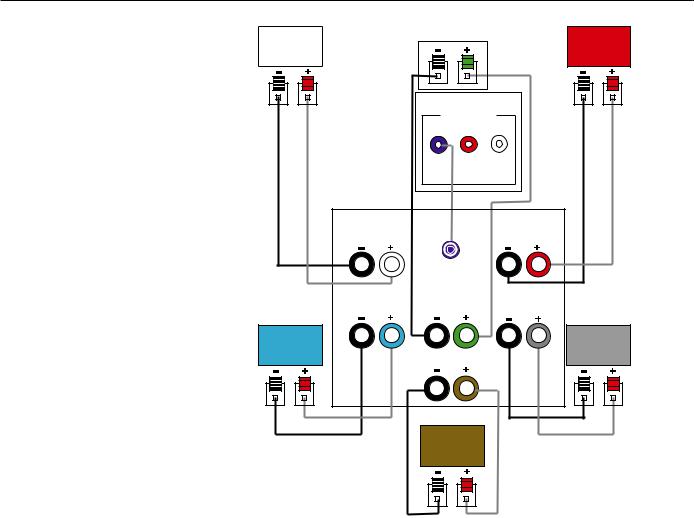
Dolby Pro Logic* (Non-Digital) – Line Level
USE THIS INSTALLATION METHOD FOR DOLBY PRO LOGIC APPLICATIONS (NOT DOLBY DIGITAL, DTS OR OTHER DIGITAL PROCESSING), WHERE THE RECEIVER/ PROCESSOR IS EQUIPPED WITH A SUBWOOFER OUTPUT, OR A VOLUMECONTROLLED PREAMP (LINE-) LEVEL OUTPUT:
Use the supplied RCA-type interconnect cable to connect the line-level subwoofer output on your receiver or amplifier to either the left or right Line-Level Full-Range Input § on the subwoofer. Use
both the left and right inputs on the subwoofer if your receiver or processor has both left and right line-level outputs. In that case, you will need to supply a second interconnect cable.
If your receiver is equipped with line-level outputs but does not have a separate subwoofer output, use a Y-adapter (not supplied) to bridge the receiver’s preamp output to the main amp input for that channel, and connect
the long end of the adapter to the corresponding line-level input on the Subwfr.
IMPORTANT: Do not use the SUB Input
∞ on the subwoofer with Dolby Pro Logic processors.
If your receiver/processor has a built-in low- pass-crossover filter for the subwoofer output, you may use the SUB Input ∞ to bypass the subwoofer’s internal crossover.
Connect each speaker to the corresponding speaker terminals on your receiver or amplifier.
Make sure that you have configured your surround sound processor for “Subwoofer On.” The front left, front right, center and surround speakers should all be set to “Small.”
When all connections have been made, plug the AC power cord on the subwoofer into an AC outlet.
|
Front |
|
|
|
Center |
|
|
Front |
||||||||||||||||||||
|
|
|
|
|
|
|
|
|
|
|
|
|
|
|
||||||||||||||
|
Left |
|
|
|
|
|
|
|
|
|
|
|
|
|
|
Right |
||||||||||||
|
|
|
|
|
|
|
|
|
|
|
|
|
|
|
||||||||||||||
|
|
|
|
|
|
|
|
|
|
|
|
|
|
|
|
|
|
|
|
|
|
|
|
|
|
|
|
|
|
|
|
|
|
|
|
|
|
|
|
|
|
|
|
|
|
|
|
|
|
|
|
|
|
|
|
|
|
|
|
|
|
|
|
|
|
|
|
|
|
|
|
|
|
|
|
|
|
|
|
|
|
|
|
|
|
|
|
|
|
|
|
|
|
|
|
8 |
|
|
|
|
|
|
|
|
|
|
|
|
|
|
|
|
|
||
|
|
|
|
|
|
|
|
|
Subwoofer |
|
|
|
|
|
|
|
|
|||||||||||
|
|
|
|
|
|
|
|
|
|
|
|
|
|
|
|
|||||||||||||
|
|
|
|
|
|
|
|
|
|
|
|
|
|
|
|
|
|
|
|
|
|
|
|
|
|
|
|
|
|
|
|
|
|
|
|
|
|
Line-Level |
|
|
|
|
|
|
|
|
|
|
|||||||||
|
|
|
|
|
|
|
|
|
|
R |
|
|
|
|
L |
|
|
|
|
|
|
|
|
|
|
|||
|
|
|
|
|
|
|
|
|
|
|
|
|
|
|
|
|
|
|
|
|
|
|
|
|
|
|
|
|
Front |
|
Front |
Left |
|
Right |
|
SUB/LFE |
|
|
Out |
|
Surround |
|
Surround |
Left |
Center |
Right |
Surround |
|
Surround |
Left |
Surround Back |
Right |
|
|
Receiver
Surround
Back
SPEAKER CONNECTIONS 11
7

SUB-TS7/TS8 |
harman/kardon |
|
|
SPEAKER CONNECTIONS
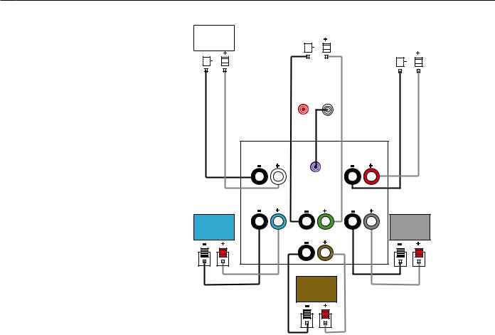
Dolby Pro Logic
(Non-Digital) – Speaker Level
USE THIS INSTALLATION METHOD FOR DOLBY PRO LOGIC APPLICATIONS (NOT DOLBY DIGITAL, DTS OR OTHER DIGITAL PROCESSING), WHERE THE RECEIVER/ PROCESSOR DOES NOT HAVE A SUBWOOFER OUTPUT, OR A VOLUMECONTROLLED PREAMP (LINE-) LEVEL OUTPUT:
Connect your receiver or amplifier’s front left and right speaker terminals to the left
and right Speaker-Level Input • terminals on the Subwfr subwoofer that are
marked “High Level In.” Connect the left and
right Speaker-Level Output ¶ terminals on the Subwfr subwoofer that are marked
“High Level Out” to the corresponding terminals on the back of your front left and right speakers.
Connect your receiver or amplifier’s center and surround speaker terminals to the corresponding terminals on the back of your center and surround speakers.
When all connections have been made, plug the AC power cord on the subwoofer into an AC outlet.
|
Front |
|
|
Center |
|
Front |
||||||||||||||||||
|
|
|
|
|
|
|
|
|
|
|
|
|||||||||||||
|
|
Left |
|
|
|
|
|
|
|
|
|
|
|
Right |
||||||||||
|
|
|
|
|
|
|
|
|
|
|
||||||||||||||
|
|
|
|
|
|
|
|
|
|
|
|
|
|
|
|
|
|
|
|
|
|
|
|
|
|
|
|
|
|
|
|
|
|
|
|
|
|
|
|
|
|
|
|
|
|
|
|
|
|
|
|
|
|
|
|
|
|
|
|
|
|
|
|
|
|
|
|
|
|
|
|
|
|
|
|
|
|
|
|
|
|
|
|
|
|
|
|
|
|
|
|
|
|
|
|
|
|
|
|
|
|
|
|
|
|
|
|
|
|
|
|
|
|
|
|
|
|
|
|
|
|
|
|
|
|
|
|
|
|
|
|
|
|
|
|
|
|
|
|
|
|
|
|
|
|
|
|
|
|
SUB-TS8
Subwoofer
H L
I
G
H
L
E
V
E
L R
Front Left |
|
Center |
Front Right |
|||
|
|
|
|
|
|
|
Surround Left |
Surround Back Surround Right |
|
|
Surround |
Receiver |
Surround |
|
Left |
Right |
||
|
|||
|
Surround |
|
|
|
Back |
|
12 SPEAKER CONNECTIONS
8

SUB-TS7/TS8 |
harman/kardon |
|
|
OPERATION
Move the Master Power Switch ª
(marked Power) to the “•” (On) position. The Subwfr subwoofer will automatically turn itself on or go into Standby mode, depending on whether or not a signal is being sent to it by your receiver or surround processor, and provided that the MusicSense On/Off Switch £ is moved down so that it is in the AUTO position.
When your receiver or amplifier is off, or is not sending program material to the subwoofer, the subwoofer will be in Standby mode and the LED Indicator on the top of the subwoofer will turn amber. When the subwoofer senses an audio signal, it will automatically turn itself on and the LED Indicator will turn blue. If the subwoofer does not sense a signal after approximately twenty minutes, it will automatically go into Standby mode.
When the Music-Sense On/Off Switch £ is switched to the ON position, the subwoofer will remain on, whether or not program material is playing, and the LED Indicator will remain lit blue.
If you’ll be away from home for an extended period of time, or if the subwoofer will not be used, switch the Master Power Switch ª to the OFF position.
Volume
Volume can be adjusted using the
Subwoofer-Level Control ¡, as shown. Turn the control knob clockwise to increase the volume of the subwoofer, and counterclockwise to decrease the subwoofer’s volume.
Subwoofer
Level
MIN MAX
Subwoofer
Level
MIN MAX
Additional Bass Adjustments
In addition to the volume adjustments described above, the Subwfr subwoofer includes a Phase Switch ¢ and a Filter Switch ™ that can be used to adjust the bass response to suit your listening environment or taste.
In most situations, the Phase Switch ¢ should be left in the NORMAL position. If you suspect that the subwoofer is playing out of phase with the other speakers, which would tend to diminish bass response, try placing this switch in the REVERSE position. There is no harm in experimenting, and you may return the switch to the NORMAL position at any time. If you rearrange your room and reposition the speakers, it would be a good idea to check whether they are in phase by flipping this switch.
The High-Cut (Low-Pass) Filter Switch
™ limits the frequencies of the audio signal inputted to the subwoofer to the low frequencies that the subwoofer reproduces best. This allows the subwoofer to perform more efficiently, and with superior bass reproduction, minimizing distortion that might occur if the subwoofer attempted to reproduce higher frequencies. This switch should be left in the ON position, except:
1.When the SUB Input ∞ is being used, in which case it has no effect, or
2.When the Speaker-Level Inputs • or the Line-Level Full-Range Inputs § are being used with a crossover or filter aboard the receiver or processor.
In these two circumstances, place the switch in the OFF position.
OPERATION 13
9
 Loading...