


SB-10-230

harman/kardon
SB 10 / 230V Service Manual
Page 1 of 16
Harman/kardon Service Manual
SB 10/230
Passive Soundbar with active subwoofer
CONTENTS
INCLUDED ITEMS 2
SUBWOOFER REAR PANEL
CONNECTIONS 5
OPERAT
TROUBLESHOOTING 8
SPECIFICATIONS
ION 7
9
3
SOUNDBAR PACKAGE LIST AND PARTS 10
PL
SOUNDBAR EX
SUBW
SUBW
SUBWOOFER SCHEMATIC DIAGRAMS
OOF
OOF
ER PA
ER EXPL
ODED VIEW / PARTS 11
CKAGE LIST A
ODED VIE
ND PARTS 12
W / PARTS 13
14
Released EU2010 Harman Consumer Group, Inc. Rev 0, 12/2010
8500 Balboa Boulevard
Northridge, California 91329

SB 10
harman/kardon
SB 10 / 230V Service Manual
Page 2 of 16
Included Items
Included Items
One SB 10 three-channel soundbar speaker
One 8" (203mm) 200-watt subwoofer
One combination LFE/trigger cable
Important: If anything is missing, or if any part of your SB 10 system fails to operate
properly, contact your dealer immediately.
Two wall-mount brackets for the SB 10 soundbar
Three speaker cables
5
SB 10
PL0004-01001
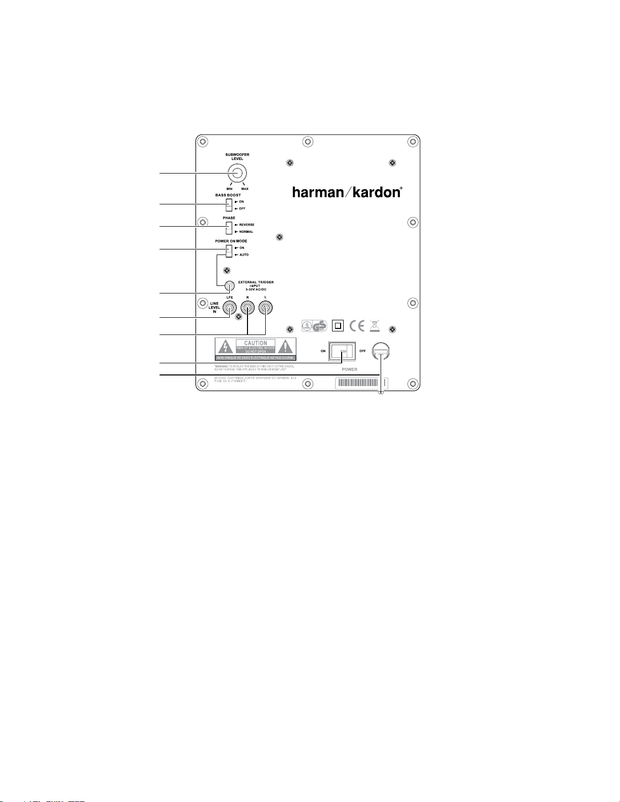
Subwoofer
Level Control
Bass Boost
Switch
Phase Switch
Power On Mode
Switch
External Trigger
Input Connector
Line-Level In
LFE Connector
Line-Level In
L/R Connectors
Power Switch
Power Cord
harman/kardon
SB 10 / 230V Service Manual
Page 3 of 16
Subwoofer Rear-Panel Connections
Subwoofer Rear-Panel Controls
Phase Switch: This switch determines whether the subwoofer driver’s piston-like action
moves in and out in phase with the satellite speakers. If the subwoofer were to play out
of phase with the satellite speakers, the sound waves from the satellites could cancel out
some of the sound waves from the subwoofers, reducing bass performance and sonic
impact. This phenomenon depends in part on the placement of all the speakers relative
to each other in the room.
Bass Boost Switch: Set this switch to “On” to enhance the subwoofer’s low-frequency
performance. Set this switch to “Off” for normal low-frequency performance.
Power-On Mode Switch: When this switch is set in the “Auto” position and when the
Power Switch is set to “On,” the subwoofer will automatically turn itself on when it
receives an audio signal and will enter the Standby mode when it has gone without
receiving an audio signal for 20 minutes. When this switch is set in the “On” position, the
subwoofer will remain on whether or not it is receiving an audio signal.
When the Power-On Mode Switch is in the “Auto” position, the LED light next to the
switch indicates whether the subwoofer is in the On or Standby mode:
When the LED glows blue, the subwoofer is in the On mode. •
When the LED is off, the subwoofer is in Standby mode. •
When the Power Switch is set to “Off,” the LED will not light up, no matter what setting
the Power-On Mode Switch is in.
Subwoofer Level Control: Use this control to adjust the subwoofer’s volume. Turn the
knob clockwise to increase the volume; turn the knob counterclockwise to decrease the
volume.
External Trigger Input Connector: Use the mini-plug of the supplied combination LFE
and trigger cable to connect the External Trigger Input Connector to the trigger output
of another compatible component. Whenever the subwoofer amplifier detects a trigger
signal between 3V and 30V (AC or DC) the amplifier will turn on. The subwoofer
amplifier will turn off after the trigger signal ceases, even when the Power-On Mode
Switch is in the “Auto” position.
Line-Level In LFE Connector: This input bypasses the subwoofer’s internal crossover
circuitry, so use it only with a receiver or processor subwoofer output that has been
low-pass filtered. If your receiver or processor does not have a dedicated subwoofer
output that is low-pass filtered, you should use the subwoofer’s Line-Level In L/R
Connectors instead (see below).
Use the supplied LFE cable (the one with purple connectors) to connect the Line-Level In
LFE Connector to the dedicated subwoofer output of a receiver or preamp/processor.
Line-Level In L/R Connectors: These inputs pass through the subwoofer’s built-in
crossover. Use them if your receiver or preamp/processor does not have a dedicated
subwoofer output that is low-pass filtered.
If your receiver or preamp/processor has a subwoofer output, use the supplied •
LFE/trigger cable to connect it to either one of the subwoofer’s Line-Level L/R In
Connectors.
If your receiver or preamp/processor does not have a separate subwoofer output, •
use two Y-adapters (not supplied). Connect an adapter’s single end to the unit’s
preamp output for that channel. Connect one of the adapter’s dual ends to the
main amp input for that channel, and connect the adapter’s other dual end to
one of the subwoofer’s Line-Level L/R In Connectors. Repeat the process with the
other Y-adapter, preamp channel, main amp input and subwoofer Line-Level L/R
In Connector.
Power Switch: Set this switch in the “On” position to turn the subwoofer on. The
subwoofer will then be in either On or Standby mode, depending on the setting of the
Power-On Mode Switch.
Power Cord: After you have made and verified all subwoofer and speaker connections
described in this manual, plug this cord into an active, unswitched electrical outlet for
proper operation of the subwoofer. DO NOT plug this cord into the accessory outlets
found in some audio components.
6
SB 10
SB 10 Soundbar
Listening Position
Subwoofer
600mm
25mm
harman/kardon
SB 10 / 230V Service Manual
Page 4 of 16
Speaker Placement
Speaker Placement
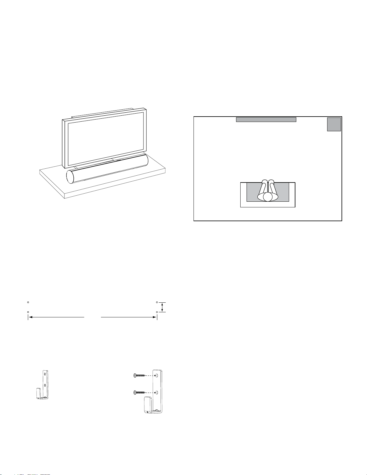
Placing the Soundbar on a Table
If your TV is placed on a table, you can place the soundbar on the table directly in front of
the TV stand, centered with the TV screen. As long as the surface of the table is flat, the
soundbar will rest on its rubber bumpers.
If your TV is located in an entertainment or media center, you can mount the soundbar in
a space directly above or below the TV.
Warning: Do NOT place the soundbar directly on top of a TV or at the front of a table or
cabinet. It could roll forward and injure someone.
Wall-Mounting the Soundbar
If your TV is attached to a wall, you can use the included wall-mount brackets to mount
the soundbar on the wall directly below the TV screen.
Determine the location for the soundbar on the wall. Make sure that the top
1.
of the soundbar will not block your view of the TV screen when it is mounted
on the wall.
Mark the locations of the soundbar wall-mount bracket holes on the wall. The
2.
holes for the left and right brackets are spaced 600mm (23-5/8") apart. The
top and bottom holes for each bracket are spaced 25mm (1") apart. See the
illustration below.
Placing the Subwoofer
Since our ears cannot locate the source of sounds at the low frequencies that the
subwoofer produces, it will perform well from just about any location in your room.
However, you are likely to hear the strongest bass reproduction when you place the
subwoofer in a corner along the same wall as the soundbar.
You can determine the best location for the subwoofer by temporarily placing it in the
listening position and playing music with strong bass content. Move around to various
locations in the room while the system is playing, and listen until you find the location
where the bass performance is best. Place the subwoofer in that location.
(n ot t o sc ale )
NOTE: To ensure that the soundbar will be level, use a carpenter’s level, laser sight or
other device to help you determine that the two sets of holes are at exactly the same
height.
Attach the two wall-mount brackets to the wall at the locations you marked, using
hardware that is appropriate for the wall’s construction and materials. Note that the
soundbar weighs 3.67kg (8.1 lb). Be sure to use hardware that can support this weight.
After making all of the connections described in the Connections section, on page 8,
attach the soundbar to the brackets by sliding the slots in its rubber bumpers onto the
brackets’ vertical tabs.
7
SB 10
+–
+–
+–
FRONT
LEFT
+–
+–
SURROUND
RIGHT
CENTER
L C R
–+–+–+
Speaker Wires
(included)
SB 10 Soundbar
Receiver or Amplifier
–+
1. Push Down on
Cap to Open Hole
2. Insert Wire Into
Open Hole
3. Release Cap to
Secure Wire
SUBWOOFER
LFE OUT
+–
+–
+–
FRONT
LEFT
RIGHT
+–
+–
SURROUND
LEFT
RIGHT
CENTER
LFE Cable
(included)
Receiver or Amplifier
Subwoofer
harman/kardon
SB 10 / 230V Service Manual
Page 5 of 16
Connections
Connections
CAUTION: Before making speaker connections, be sure that your receiver or amplifier
is turned off. If possible, make sure that its AC cord is unplugged from the AC power
outlet.
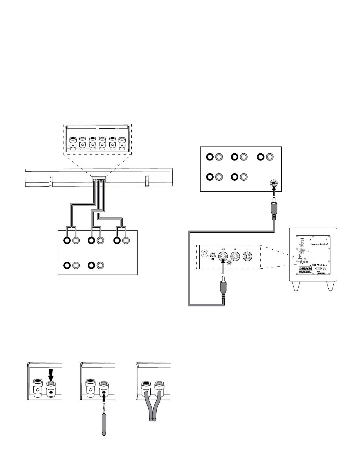
Soundbar Connections
The SB 10 soundbar contains left-, center- and right-channel speakers that connect
to your audio/video receiver or amplifier’s front left, center and front right speaker
outputs.
IMPORTANT: Make sure the (+) and (–) bare wires do not touch each other or the other
terminal. Touching wires can cause a short circuit that can damage your receiver or
amplifier.
Subwoofer Connections
1a. If your receiver/processor has a dedicated subwoofer output with low-pass
filtering (also called bass management), use the included LFE cable to connect
the
subwoofer
LFE output) of your receiver or preamp/processor.
Configure your receiver or preamp/processor’s setup menu for Subwoofer ON, and set
the front left, front right, center and surround speakers to Small.
’s Line-Level LFE In jack to the dedicated subwoofer output (or
To connect each wire to the soundbar:
Press down on the terminal cap to open the connection hole on the soundbar’s
1.
speaker terminal.
Insert the wire’s bare end all the way into the hole. Insert the conductor with the
2.
3.
8
colored band into the speaker’s red (+) terminal, and insert the other conductor
into the speaker’s black (–) terminal, as shown in the illustration.
Release the cap to secure the wire.
 Loading...