


AVR5
Harman Kardon
AVR5
Audio/V ideoReceiver
Owner’s Manual

Owner’s Manual
AVR5 Audio/Video Receiver
Table of Contents
Introduction. . . . . . . . . . . . . . . . . . . . . . . . . . . . . . . . . . . . . . . . . 1
Safety Information . . . . . . . . . . . . . . . . . . . . . . . . . . . . . . . . . 2–3
Front Panel Controls . . . . . . . . . . . . . . . . . . . . . . . . . . . . . . . 4–6
Rear Panel Connections . . . . . . . . . . . . . . . . . . . . . . . . . . . . . 7–8
Remote Control Functions . . . . . . . . . . . . . . . . . . . . . . . . . . 9–11
Installation and Connections. . . . . . . . . . . . . . . . . . . . . . . 12–13
System Configuration . . . . . . . . . . . . . . . . . . . . . . . . . . . . . 14–17
Operation. . . . . . . . . . . . . . . . . . . . . . . . . . . . . . . . . . . . . . . 18–22
Source Selection . . . . . . . . . . . . . . . . . . . . . . . . . . . . . . 18
Surround Mode Selection. . . . . . . . . . . . . . . . . . . . 19–20
Surround Mode Chart . . . . . . . . . . . . . . . . . . . . . . . . . . 19
6-Channel Direct Operation . . . . . . . . . . . . . . . . . . . . . 20
External Amplifier Connection. . . . . . . . . . . . . . . . . . . 20
Tuner Operation . . . . . . . . . . . . . . . . . . . . . . . . . . . 20–21
Tape Recording. . . . . . . . . . . . . . . . . . . . . . . . . . . . 21–22
Output Level Trim Adjustment . . . . . . . . . . . . . . . . . . . 22
Programming the Remote . . . . . . . . . . . . . . . . . . . . . . . . . 23–34
Direct Code Entry. . . . . . . . . . . . . . . . . . . . . . . . . . . . . . 23
Auto Search Method . . . . . . . . . . . . . . . . . . . . . . . . . . . 23
Code Readout. . . . . . . . . . . . . . . . . . . . . . . . . . . . . . . . . 24
Programmed Device Functions . . . . . . . . . . . . . . . 24–25
Function List. . . . . . . . . . . . . . . . . . . . . . . . . . . . . . 26–27
Setup Code Tables: TV. . . . . . . . . . . . . . . . . . . . . . . 28–30
Setup Code Tables: VCR . . . . . . . . . . . . . . . . . . . . . 31–32
Setup Code Tables: DVD . . . . . . . . . . . . . . . . . . . . . . . . 33
Setup Code Tables: LD. . . . . . . . . . . . . . . . . . . . . . . . . . 34
Troubleshooting Guide . . . . . . . . . . . . . . . . . . . . . . . . . . . . . . . 35
Technical Specifications . . . . . . . . . . . . . . . . . . . . . . . . . . . . . . 36
©1998 Harman Kardon, Incorporated
250 Crossways Park Drive
Woodbury, NY 11797

Congratulations! With the purchase
of the Harman Kardon AVR5 you are
about to begin many years of listening
enjoyment. The AVR5 has been custom
designed to provide all the excitement
and detail of movie sound tracks and
every subtle nuance of musical selections.
While complex systems are hard at work
within the AVR5 to make all of this hap-
pen, hookup and operation are simple.
Color-keyed connections and a compre-
hensive programmable remote control
make the AVR5 easy to use.
To obtain maximum enjoyment from
your new receiver, we urge you to take a
few minutes to read through this manual.
This will ensure that connections to
speakers, source playback units and other
external devices are made properly. In
addition, a few minutes spent learning
the functions of the various controls will
enable you to take advantage of all the
power the AVR5 is able to deliver.
Introduction
4
If you have any questions about this
product, its installation or operation,
please contact your dealer. They are your
best local source of information.
Description and Features
The AVR5 is a full-featured A/V receiver,
incorporating a wide variety of listening
options. In addition to Dolby
*
Pro Logic
*
and Dolby 3 Stereo, with “6-Channel
Direct” inputs, the AVR5 is ready for the
future. The AVR5 is digital ready, and
may be connected to an optional, exter-
nal digital decoder, or the outputs of a
DVD player, Digital TV or any product
that has its own Dolby Digital or DTS
†
decoder. A choice of Hall and Theater
modes is also available for use with
both encoded sources and traditional
two-channel stereo recordings.
A total of four audio/video inputs, as well
as two additional audio-only inputs, and
an FM stereo/FM/AM tuner provide for
the utmost flexibility. Front-panel A/V
inputs simplify connections to video
games or camcorders. A high-quality
phono input is available so that you may
continue to enjoy your existing record
collection as well as the latest surround
technologies.
The AVR5’s powerful amplifiers use
traditional Harman Kardon High-Current
Design philosophies to meet the wide
dynamic range of any program selection.
Harman Kardon invented the high-
fidelity receiver more than forty-five years
ago. With state-of-the-art features and
time-honored circuit designs, the AVR5 is
one of the finest receivers ever offered by
Harman Kardon.
■ Five Analog Surround Modes
■ Pre-Programmed Remote Control
■ Composite Video Switching
■ Six-Channel Direct Input Enables
Seamless Integration of Future
Decoding Systems
■ Preamp Output for ALL Channels
Permits Ease of Expansion
■ Phono Input Section
Safety Information
Important Safety Information
Verify Line Voltage Before Use
YourAVR5hasbeen designed for use with
120-volt ACcurrent. Connection toa line
voltage otherthan that forwhich it is
intended cancreate a safetyand fire haz-
ard, andmay damage theunit.
If you have any questions about the volt-
age requirements for your specific model,
or about the line voltage in your area,
contact your selling dealer before plug-
ging the unit into a wall outlet.
Do Not Use Extension Cords
To avoid safety hazards, use only the
power cord attached to your unit. We do
not recommend that extension cords be
used with this product. As with all electri-
cal devices, do not run power cords under
rugs or carpets or place heavy objects on
them. Damaged power cords should be
replaced immediately with cords meeting
factory specifications.
Handle the AC Power Cord Gently
When disconnecting the power cord from
an AC outlet, always pull the plug, never
pull the cord. If you do not intend to use
the unit for any considerable length of
time, disconnect the plug from the AC
outlet.
Do Not Open the Cabinet
There are no user-serviceable compo-
nents inside this product. Opening the
cabinet may present a shock hazard, and
any modification to the product will void
your guarantee. If water or any metal
object such as a paper clip, wire or
staple accidentally falls inside the unit,
disconnect it from the AC power source
immediately, and consult an authorized
service station.
CATV or Antenna Grounding
If an outside antenna or cable system is
connected to this product, be certain that
it is grounded so as to provide some pro-
tection against voltage surges and static
charges. Section 810 of the National
Electrical Code, ANSI/NFPA No. 70-1984,
provides information with respect to
proper grounding of the mast and sup-
porting structure, grounding of the lead-
in wire to an antenna discharge unit,
size of grounding conductors, location of
antenna discharge unit, connection to
grounding electrodes and requirements
of the grounding electrode.
NOTE TO CATV SYSTEM INSTALLER:
This reminderis provided tocall the
CATV(Cable TV)system installer’satten-
tion toarticle 820-40 ofthe NEC that
provides guidelinesfor proper grounding
and, inparticular,specifies that thecable
ground shallbe connected tothe ground-
ing systemof the building,as close to the
point ofcable entry aspossible.
Installation Location
■ To assure proper operation, and to
avoid the potential for safety hazards,
place the unit on a firm and level sur-
face. When placing the unit on a shelf,
be certain that the shelf and any
mounting hardware can support the
weight of the product.
■ Make certain that proper space is pro-
vided both above and below the unit
for ventilation. If this product will be
installed in a cabinet or other enclosed
area, make certain that there is suffi-
cient air movement within the cabinet.
Under some circumstances a fan may
be required.
■ Do not place the unit directly on a
carpeted surface.
■ Avoid installation in extremely hot or
cold locations, or an area that is
exposed to direct sunlight or heating
equipment.
■ Avoid moist or humid locations.
■ Do not obstruct the ventilation slots on
the top of the unit, or place objects
directly over them.
5
CAUTION:
TO REDUCE THE RISK OF ELECTRIC SHOCK, DO NOT REMOVE
COVER (OR BACK). NO USER-SERVICEABLE PARTS INSIDE. REFER
SERVICING TO QUALIFIED SERVICE PERSONNEL.
WARNING:
TO REDUCE THE RISK OF FIRE OR ELECTRIC SHOCK,
DO NOT EXPOSE THIS APPLIANCE TO RAIN OR MOISTURE.
CAUTION:
TO PREVENT ELECTRIC SHOCK, MATCH WIDE
BLADE OF PLUG TO WIDE SLOT, FULLY INSERT.
ATTENTION:
POUR EVITER LES CHOCS ELECTRIQUES, INRODUIRE LA
LAME LA PLUS LARGE DE LA FICHE DANS LA BORNE CORRESPONDANTE DE
LA PRISE ET POUSSER JUSQU'AU FOND.
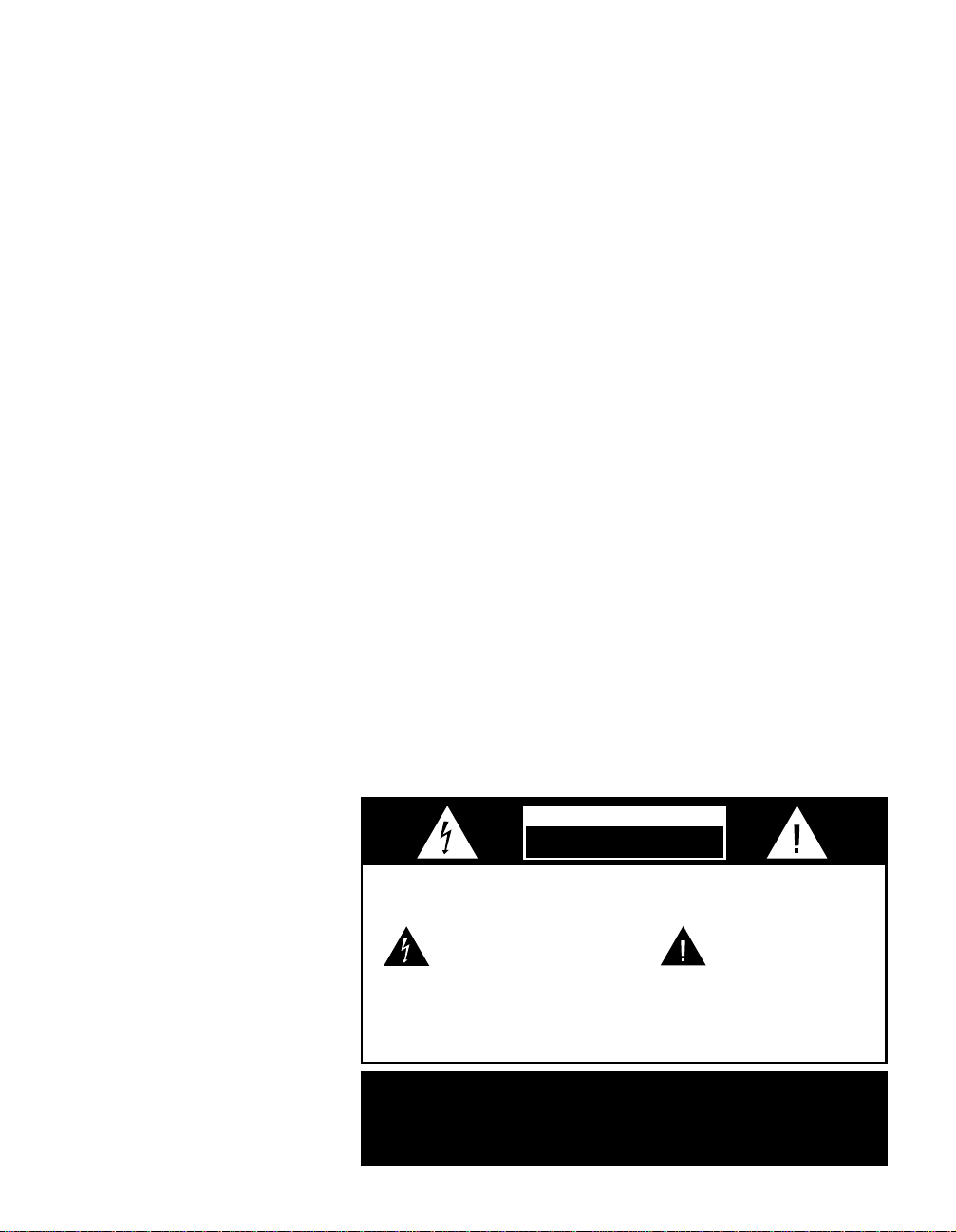
The lightning flash with arrowhead
symbol, within an equilateral triangle, is
intended to alert the user to the
presence of uninsulated “dangerous voltage”
within the product’s enclosure that may be of
sufficient magnitude to constitute a risk of
electric shock to persons.
The exclamation point within an
equilateral triangle is intended to
alert the user to the presence of
important operating and maintenance
(servicing) instructions in the literature
accompanying the appliance.
CAUTION
RISK OF ELECTRIC SHOCK
DO NOT OPEN

Safety Information
Cleaning
When the unit gets dirty, wipe it with a
clean, soft, dry cloth. If necessary, wipe it
with a soft cloth dampened with mild
soapy water, then a fresh cloth with clean
water. Wipe dry immediately with a dry
cloth. NEVER use benzene, aerosol
cleaners, thinner, alcohol or any other
volatile cleaning agent. Do not use
abrasive cleaners, as they may damage
the finish of metal parts. Avoid spraying
insecticide near the unit.
Moving the Unit
Before moving the unit, be certain to dis-
connect any interconnection cords with
other components, and make certain
that you disconnect the unit from the
AC outlet.
Important Information For the User
NOTE: This equipment has been tested
and found to comply with the limits for
a Class-B digital device, pursuant to Part
15 of the FCC Rules. The limits are
designed to provide reasonable protection
against harmful interference in a
residential installation. This equipment
generates, uses and can radiate radio-
frequency energy and, if not installed and
used in accordance with the instructions,
may cause harmful interference to radio
communication. However, there is no
guarantee that harmful interference will
not occur in a particular installation.
If this equipment does cause harmful
interference to radio or television recep-
tion, which can be determined by turning
the equipment off and on, the user
is encouraged to try to correct the inter-
ference by one or more of the following
measures:
■ Reorient or relocate the receiving
antenna.
■ Increase the separation between the
equipment and receiver.
■ Connect the equipment into an outlet
on a circuit different from that to
which the receiver is connected.
■ Consult the dealer or an experienced
radio/TV technician for help.
Thisdevice complies withPart 15 ofthe
FCCRules. Operation issubject to the
followingtwo conditions: (1)this device
maynot cause harmfulinterference, and
(2)this device mustaccept interference
received,including interference thatmay
causeundesired operation.
NOTE: Changes or modifications may
cause this unit to fail to comply with
Part 15 of the FCC Rules and may void
the user’s authority to operate the
equipment.
Unpacking
The carton and shipping materials used
to protect your new receiver during ship-
ment were specially designed to cushion
it from shock and vibration. We suggest
that you save the carton and packing
materials for use in shipping if you move,
or should the unit ever need repair.
To minimize the size of the carton in
storage, you may wish to flatten it. This
is done by carefully slitting the tape
seams on the bottom and collapsing the
carton down to a more two-dimensional
appearance. Other cardboard inserts may
be stored in the same manner. Packing
materials that cannot be collapsed
should be saved along with the carton in
a plastic bag.
If you do not wish to save the packaging
materials, please note that the carton
and other sections of the shipping protec-
tion are recyclable. Please respect the
environment and discard those materials
at a local recycling center.
Typographic Conventions
In order to help you use this manual
with the remote control, front panel
controls and rear panel connections,
certain conventions have been used.
Example – (bold type) indicates a
specific remote control or front panel
button, or rear panel connection
Example – (OCR type) indicates a
message that is visible on the front panel
information display
EXAMPLE – (bold type) indicates a lit
indicator in the front panel information
display
1 – (number in a square) indicates a
specific front panel control
¡ – (number in a circle) indicates
a rear panel connection
å – (letter in a circle) indicates a
button on the main portion of the
remote control
A – (letter in a square) indicates a
button under the sliding panel on the
lower portion of the remote control
6
Front Panel Controls
7
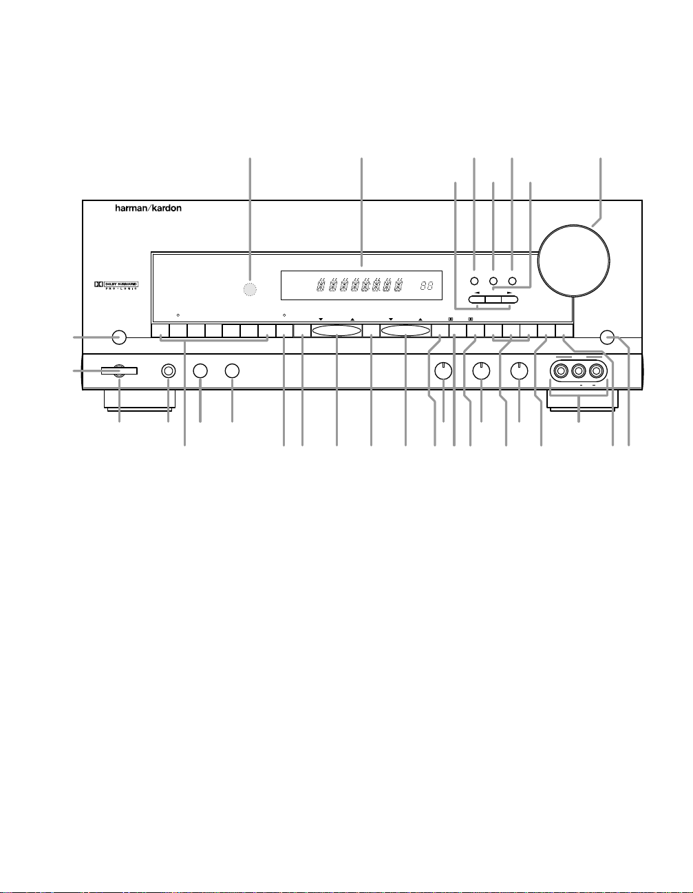
1 Main Power Switch
2 System Power Control
3 Power Indicator
4 Headphone Jack
5 Speakers ON
6 Speakers OFF
7 Bass Control
8 Treble Control
9 Balance Control
) Video 3 Inputs
! Input Selectors
@ 6-Channel Direct Selector
# AM/FM
$ Tuning Button
% Preset Scan
^ Preset Stations Selector
& FM Mode
* Dolby Pro Logic Selector
( Dolby 3 Stereo Selector
Ó Analog Surround Mode Selectors
Ô Test Tone
Surround Off
Ò Mute
Ú Volume Control
Û Set Button
Ù Delay
ı Channel Select
ˆ Center Speaker Select Button
˜ Selector Buttons
¯ Information Display
˘ Remote Sensor Window
AVR 5
PHONO CD DVD VID 1 VID 2 VID 3
AM/FM PRESET SCAN FM MODE
PRO LOGIC
3-STEREO
HALL 1 HALL 2 THEATER TEST TONE SURR. OFF
PRESET
TUNING
Phones
Power
Mute
RLMaxMinMaxMin
Bass Treble Balance
Volume
Center Channel Delay
Set
VIDEO 3
Video Audio RL
T•MON 6 CH
Speakers
OffOn
TUNED STEREO MONO MEMO PRO
MIN
MHz
PRESET
MHz
LOGIC
SURROUND
SLEEP
!
@
# $ % ^
*
3
4
5 6
7 8 9 )
1
2
&( Ô Ò
Ú
˜
ˆ
Û
Ù
ı
Ó
¯˘

Front Panel Controls
8
1 Main Power Switch: Press this
button to apply power to the AVR5.
When the switch is pressed in the
unit is placed in a Standby mode,
as indicated by the amber LED 3
surrounding the System Power
Control 2. This button MUST be
pressed in to operate the unit. To turn
the unit off and prevent the use of the
remote control, this switch should be
pressed until it pops out from the
front panel so that the word “OFF”
may be read at the top of the switch.
NOTE: In normal operation this
switch is left in the “ON” position.
2 System Power Control: When
the Main Power Switch
1
is “ON,”
press this button to turn on the
AVR5; press it again to turn the unit
off. Note that the Power Indicator
surrounding the switch
3
will turn
green when the unit is on.
3 Power Indicator: This LED will
illuminate in amber when the unit is
in the Standby mode to signal that
the unit is ready to be turned on.
When the unit is in operation, the
indicator will turn green. A red indi-
cator means that the unit is in the
Protect mode, and should be turned
off and then checked for a possible
speaker wire short circuit.
4 Headphone Jack: This jack may
be used to listen to the AVR5’s out-
put through a pair of headphones.
Be certain that the headphones
have a standard
1
⁄4" stereo phone
plug.
7 Bass Control: Turn this control to
modify the low-frequency output of
the left/right channels by as much as
±10dB. Set this control to a suitable
position for your taste and room
acoustics.
5 Speakers ON Button: This
button turns the speakers on for
normal listening.
6 Speakers OFF Button: This but-
ton turns the speakers off for private
listening when the headphones are
in use.
8 Treble Control:Turn this control
to modify the high-frequency output
of the left/right channels by as much
as ±10dB. Set this control to a
suitable position for your taste and
room acoustics.
9 Balance Control: Turn this
control to change the relative volume
for the front left/right channels.
NOTE: For proper operation of the
surround modes this control should
be at the midpoint, or “12 o’clock”
position.
) Video 3 Inputs: These
audio/video inputs may be used
for temporary connection of video
games, camcorders, digital still
cameras or portable audio products.
To select a source connected to
these jacks, press the Vid 3 Input
Selector !.
! Input Selectors: Press one of
these buttons to select or change
the input source. If the unit is in the
Standby mode, pressing one of these
buttons will also turn the AVR5 on.
@ 6-Channel Direct Selector:
Press this button to select the output
of an optional, external 6-channel
decoder connected to the 6 Ch
Direct inputs ° as the listening
source.
# AM/FM: Press this button to
select the tuner as the AVR5’s input
source. When it is first pressed the
last station tuned will be heard.
Press it again to change between
AM and FM bands.
$ Tuning Button: Press the left
side of the button to tune lower
frequency stations and the right side
of the button to tune higher frequency
stations. When a station with a strong
signal is tuned, the TUNED indicator
will illuminate in the Information
Display ¯. A brief (1/2 second)
press of the button will manually
tune to the next frequency incre-
ment, while pressing and holding
the button for a longer period will
automatically tune to the next station
with a signal strong enough for
acceptable reception.
% Preset Scan: Press this button
to automatically scan through the
stations that have been programmed
in the AVR5’s memory. The tuner will
play five seconds of each station
before moving to the next preset
station. To stop the scan when the
desired station is heard, press the
button again. (See page 21 for more
information on the tuner memory
system.)
^ Preset Stations Selector: Press
this button to select stations that
have been entered into the preset
memory. (See page 21 for more
information on tuner programming.)

Front Panel Controls
& FM Mode: Press this button to
select the stereo or mono mode for
FM tuning. In the STEREO mode a
Stereo indicator will illuminate in the
Information Display ¯, and stereo
reception will be provided when sta-
tions are transmitting stereo signals.
In the MONO mode the left and right
signals from stereo broadcasts will
be mixed together and reproduced
through all channels. Select MONO
for better reception of weak signals.
* Dolby Pro Logic Selector: Press
this button to select the Dolby Pro
Logic surround mode when listening
to an analog program that is encoded
with surround-sound information. (See
page19 for more information on
surround modes.)
( Dolby 3 Stereo Selector: Press
this button to select the Dolby 3
Stereo listening mode. This mode
is used primarily when a program
has surround information when a
center channel speaker, but no
surround speakers, is installed.
(See page 19 for more information
on surround modes.)
Ó Analog Surround Mode
Selectors: Press one of these
buttons to select the analog sur-
round modes. These modes may
be used with any analog program
source to create a pleasing surround
effect. (See page 19 for more
information on surround modes.)
Ô Test T one: Press this button to
begin the sequence of steps used to
set the AVR5’s output levels. When this
button is pressed, a test tone will
replace the currently selected listening
source and the Information Display
¯ will show the channel where the
test tone appears. The test tone will
automatically switch to the next chan-
nel after three seconds. (See page 16
for more information on using the test
tone to set the output levels.)
Surround Off: Press this button
to turn off all surround processing,
and to listen to a program in tradi-
tional stereo from the left front and
right front speakers only.
Ò Mute: Press this button to
momentarily silence the speaker
output of the AVR5.
Ú Volume Control: Turn the knob
clockwise to increase volume,
counterclockwise to decrease the
volume.
Û Set Button: This button has
two functions. If this button is
pressed while in normal operation,
the Information Display ¯ will
show the Surround mode for three
seconds. This button is also used to
enter an output level setting when
using the Test T one and Selector
Buttons Ô˜. (See pages 15–17
for more information on setting
output levels.)
Ù Delay: Press this button to enter
delay time settings. (See page 17 for
more information on delay times.)
ı Channel Select: Press this
button during normal operation, or
during the Test Tone operation, to
begin the process that adjusts the
output levels.
NOTE: Be sure to select the Dolby
Pro Logic surround mode before cal-
ibration so that all five channels will
be adjusted. (See page16 for more
information on setting output levels.)
ˆ Center Speaker Select Button:
Press this button to select the center
channel speaker . When it is first
pressed, the Information Display
¯ will show the currently selected
speaker type. Press it again to show
another speaker type or no speaker
option (this option is available with the
Dolby Pro Logic surround mode only).
Release this button when a desired
selection is shown in the Information
Display ¯. (See page 15 for more
information on setting the center
channel type.)
˜ Selector Buttons: Press these
buttons to adjust the AVR5’s output
levels. You may use these buttons
while you are checking the output
levels by pressing either the Test
Tone ButtonÔ or the Channel
Select Button ı.
NOTE: Be sure to press the Set Button
Û to enter a new output level each
time you adjust the channel. (See
pages 15–17 for information on set-
ting output levels using the test tone,
or page 22 for information on output
level trim using a normal program
source.)
¯ Information Display: This
display delivers messages and
status indications to help you
operate the receiver.
˘ Remote Sensor Window: The
sensor behind this window receives
infrared signals from the remote con-
trol. Aim the remote at this area and
do not block or cover it unless an
external remote sensor is installed.
9
Rear Panel Connections
10
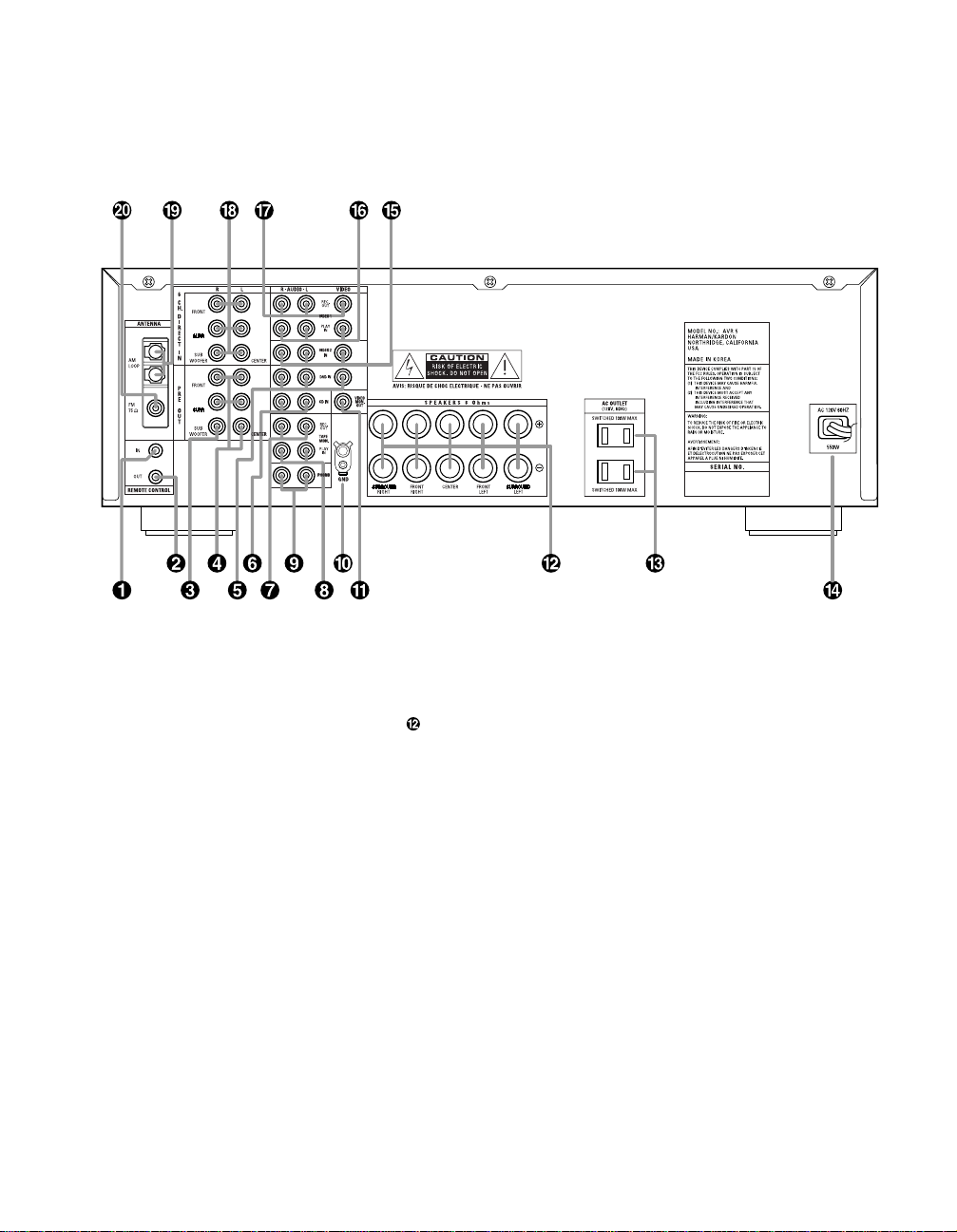
¡ Remote IR In
™ Remote IR Out
£ Subwoofer Pre-Out
¢ Pre-Outs
∞ DVD Inputs
§ CD Inputs
¶ Tape Monitor Out
• Tape Monitor In
ª Phono Inputs
‚ Phono Ground
⁄ TV Monitor Video Output
Speaker T erminals
‹ Switched AC Outlets
› Power Cable
fi Video 2 Inputs
fl Video 1 Inputs
‡ Video Outputs 1
° 6-Channel Direct Inputs
· AM Antenna
a FM Antenna
¡ Remote IR In: If the AVR5’s front
panel IR sensor is blocked due to
cabinet doors or other obstructions,
an external IR sensor may be used.
Connect the output of the sensor to
this jack.
™ Remote IR Out: This connection
permits the IR sensor in the receiver
to serve other remote controlled
devices. Connect this jack to the “IR
IN” jack on Harman Kardon or other
compatible equipment.
£ Subwoofer Pre-Out: Connect
this jack to the line level input of a
powered subwoofer. If an external
subwoofer amplifier is used, connect
this jack to the subwoofer amplifier
input.
¢ Pre-Outs: If external power
amplifiers are used for any channels,
connect them to these jacks.
∞ DVD Inputs: Connect the analog
audio outputs and composite video
output of a DVD or LV player to
these jacks.
§ CD Inputs: Connect these jacks
to the output of a compact disc
player or CD changer.
¶ Tape Monitor Out: Connect these
jacks to the RECORD/INPUT jacks of
an audio recorder.
• Tape Monitor In: Connect these
jacks to the PLAY/OUT jacks of an
audio recorder.

Rear Panel Connections
11
ª Phono Inputs: Connect the out-
puts of your turntable or tone arm to
these jacks. Note that only Moving
Magnet (MM) type cartridges may
be used.
‚ Phono Ground: Connect the
ground wire from a turntable to this
terminal to reduce system hum.
⁄ TV Monitor Video Output:
Connect this jack to the standard
(composite) video input of a TV
monitor or video projector to view
the output of any standard video
source selected by the receiver’s
video switcher.
Speaker Terminals: Connect
these terminals to the appropriate
terminals on your speakers.
‹ Switched AC Outlets: These out-
lets may be used to power any
device that you wish to have turn on
when the unit is turned on with the
System Power Control switch 2.
NOTE: The power consumption of
the device plugged into each of
these outlets should not exceed
100 watts.
› Power Cable: Connect the AC
plug to a non-switched AC wall
output
fi Video 2 Inputs: Connect these
jacks to the audio and video outputs
of a TV Tuner, Cable TV converter
box, satellite receiver or any other
audio/video source.
fl Video 1 Inputs: Connect these
jacks to the audio and video
PLAY/OUT jacks of a VCR.
‡ Video Outputs 1: Connect these
jacks to the audio and video
RECORD/IN jacks of a VCR.
° 6-Channel Direct Inputs: If an
external digital audio decoder is
used for 5.1 (Dolby Digital, DTS,
etc.) audio, connect the outputs of
that decoder to these terminals.
· AM Antenna: Connect the AM
loop antenna supplied with the
receiver to these terminals.If an
external AM antenna is used, make
connections to the AM and GND
terminals in accordance with the
instructions supplied with the
antenna.
a FM Antenna: Connect an indoor
or external FM antenna to this
terminal.

Remote Control Functions
12
1
2
3
4
5
6
7
8
9
0
DIRECT
CTR.
PRESET
AUTO
CHAN.
SET
DELAY
MEMORY
TONE
TEST
AVR 5 RC
ON OFF
MASTER VOL.
VOLUME
DWN - TUNING - UP
DWN - PRESET - UP
AVR DVD VCR TV
SURR./CH.
MAIN POWER
6 CH.
DISC SKIP P. SCAN
FM MODE
MUTE
SLEEP
DIMMER
CLEAR
SOURCE POWER
/
AM/FM DVD
V1PHONO
TAPE V2
V3CD
:
<
>
"
}
{
å
≠
∫
∂
ƒ
ç
©
˙
∆
V
W
X
Y
Z
¬
µ
π
ø
œ
®
ß
†
å LED Indicator
∫ Main Power Off
ç Main Power On
∂ Device Control Selectors
≠ AVR Selector
ƒ Source Selectors
© 6-Channel Direct
˙ Disc Skip
Sleep Button
∆ Dimmer
Surround/Channel Selectors
¬ Clear Button
µ Master Volume
Mute
ø P•Scan
π Volume
œ FM Mode
® Transport Controls
ß Tuning Up/Down
† Preset Up/Down
Source Power
V Numeric Keys
W Direct
X Auto Preset
Y Center
Z Secondary Control Cover
{
‹
/
›
Buttons
} Set Button
: Channel Button
" Test Tone
< Delay
> Memory
Remote Control Functions
IMPORTANT NOTE: The AVR5’s
remote may be programmed to con-
trol up to three additional devices,
including the AVR5. Befor e using the
remote, it is important to remember to
press the Device Control Selector
button ∂≠that corresponds to the
unit you wish to operate. The remote
is capable of operating a wide variety
of products using the control codes
that are part of the remote. Before
using the remote with other products,
follow the instructions on pages
23–26 to program the proper codes
for the products in your system.
It is also important to remember that
many of the buttons on the remote
take on different functions, depend-
ing on the product selected using
the Device Control Selectors. The
descriptions shown here primarily
detail the functions of the remote
when it is used to operate the AVR5.
(See page 24 for information about
alternate functions for the remote’s
buttons.)
å LED Indicator: This indicator
will flash whenever a button is
pressed to confirm that a remote
command is being transmitted. It will
also flash while the remote is being
programmed to assist in entering or
reading remote codes. Note that this
is NOT a standard remote button,
and has no function when pressed.
∫ Main Power Off: When the AVR5
is turned on, press this button to
place it in the Standby mode. Note
that in this condition, the unit is still
connect to AC Power.
ç Main Power On: When the AVR5
is in the Standby mode, as indicated
by the Power Indicator 3 glowing
green, press this button to turn the
AVR5 on.
∂ Device Control Selectors: Press
one of these buttons to use the
remote to control the functions of
another audio/video device. Note
that the button will briefly turn red
after it has been pressed to confirm
your selection. (See pages 23–25 for
information on programming the
AVR5’s remote to operate these
devices.)
≠ AVR Selector: Press this button to
use the remote control for operation of
the AVR5. Note that the button will
briefly turn red after it has been
pressed to confirm your selection.
ƒ Source Selectors:Press these
buttons to select an input source for
the AVR5. The AM/FMbutton is also
used to switch between frequency
bands when the tuner is in use.
NOTE: Pressing one of these buttons
selects the source only. In order to
control the actual source machine
using the remote you must press the
Device Control Selector button ≠
for the desired product.
© 6-Channel Direct: Press this but-
ton to use the output of an optional,
external digital decoder as the
AVR5’s input source.
˙ Disc Skip: These buttons do not
have any functions when controlling
the AVR5, but they operate the Disc
Skip functions of compatible Harman
Kardon compact disc changers. The
Disc Skip Up button will also function
as the Open/Close button for certain
DVD and LD equipment when the
remote is properly programmed to
control them.
Sleep Button: Press this button
to place the unit in the Sleep mode.
After the time shown in the display,
the AVR5 will automatically go into
the Standby mode. Each press of
the button changes the time until
turn-off in the following order:
∆ Dimmer: Press this button once
to reduce the brightness of the front
panel display to half the normal
intensity. Press it again to turn the
front panel display completely off.
When the display is completely off,
press the button to return to normal
brightness.
90
min
80
min
70
min
60
min
50
min
40
min
30
min
20
min
10
min
OFF
Surround/Channel Selectors:
Press these buttons to check or
change the current Surround mode.
When either one of these two buttons
is first pressed, the Information
Display ¯ will show the current
Surround mode. Press either button
again to change the current
Surround mode by scrolling the list
of available modes as they appear
in the Information Display ¯.
When the remote is being used to
control a VCR or TV set, these but-
tons are used to change channels.
These buttons are also used when
the remote is being programmed to
“find” the correct codes via the
Search mode. (See page 23 for
more information on programming
the remote.)
¬ Clear Button: This button is used
to clear preset memory information
for the AVR5’s tuner. (See pages
21–22 for more information on tuner
presets.)
µ Master V olume: Press these
buttons to raise or lower the AVR5’s
volume. These buttons are also used
to obtain the IR code numbers for a
device that has been programmed
into the remote. (See page 23 for
more information on programming
the remote.)
Mute: Press this button to momen-
tarily silence the AVR5. When the
AVR5 r emote is being pr ogrammed to
operate another device, this button is
pressed with the Device Control
Selector button ∂ to begin the pro-
gramming process. (See page 23 for
more information on programming
the remote.)
ø P•Scan: Press this button to
automatically scan through the list of
stations that are programmed into
the AVR5’s tuner memory. When the
button is pressed, each preset sta-
tion will play for five seconds before
the next station is selected. Press
the button again when the desired
station is heard to stop the preset
scan.
13
 Loading...