


HK 3470 Stereo Receiver |
|
|
|
OWNER’S MANUAL |
|
|
|
MUTE T-MON |
AUTO |
TUNED ST |
MEMORY PRESET |
|
|
|
SLEEP |
|
VMAx |
|
|
|
|
|
® |
Power for the digital revolution.™

HK 3470 Stereo Receiver
3 Introduction
3Safety Information
4Unpacking
5Front Panel Controls
7Front Panel Information Display
8Rear Panel Connections
10 Remote Control Functions
12 Installation and Connections
14 Operation
14Basic Operation
14Source Selection
14Tuner Operation
15Tape Recording
16Remote Control Operation
17Programming the Remote
19Memory Backup
19Processor Reset
19Troubleshooting Guide
20Technical Specifications
Typographical Conventions
In order to help you use this manual with the remote control, front panel controls and rear panel connections, certain conventions have been used.
EXAMPLE – (bold type) indicates a specific remote control or front panel button, or rear panel connection jack
EXAMPLE – (OCR type) indicates a message that is visible on the front panel information display
EXAMPLE – (outlined type) indicates a lit indicator in the front panel information display
1 – (number in a square) indicates a specific front panel control
å – (letter in a circle) indicates a button or indicator on the remote
¡ – (number in a circle) indicates a rear panel connection
A – (letter in a square) indicates an indicator in the front panel display
2 TABLE OF CONTENTS
Introduction
Congratulations! With the purchase of the Harman Kardon HK 3470 you are about to begin many years of listening enjoyment. The HK 3470 has been custom-designed to provide all the excitement and power of rock, jazz and popular music, and every nuance of classical selections.
While sophisticated systems are hard at work within the HK 3470 to make all of this happen, hookup and operation are simple. Color-keyed connections and a comprehensive remote control make the HK 3470 easy to use.
To obtain maximum enjoyment from your new receiver, we urge you to take a few minutes to read through this manual. This will ensure that connections to speakers, source playback units and other external devices are made properly. In addition, a few minutes spent learning the functions of the various controls will enable you to take advantage of all the power the HK 3470 is able to deliver.
If you have any questions about this product, its installation or operation, please contact your dealer, your best local source of information.
Description and Features
Harman Kardon’s HK 3470 is the world’s first stereo receiver to offer VMAx®. VMAx is a proprietary signal-processing technique that creates an open, spacious sound field when only two loudspeakers are available. VMAx circuitry is able to decode the ambience of a concert hall or theater from a stereo recording.
The HK 3470 is a full-featured stereo receiver, with five inputs and an FM Stereo/FM/AM tuner with capabilities that provide for the utmost flexibility. A high-quality phono input is available so that you may continue to enjoy your existing record collection as well as the latest CD recordings.
The HK 3470’s powerful amplifier uses traditional Harman Kardon High-Current Design philosophies to meet the wide dynamic range of any program selection.
Harman Kardon invented the high-fidelity receiver more than forty-seven years ago. With state-of-the-art features and time-honored circuit designs, the HK 3470 is one of the finest receivers ever offered by Harman Kardon.
■Harman Kardon-Designed HighCurrent, Ultrawide-Bandwidth Amplifier
■VMAx Processing Mode – Exclusive to Harman Kardon Receivers
■Phono Input Section
■Speaker 1/Speaker 2 Outputs for HighQuality Sound in Two Locations
■Pre-Out/Main-In Jacks for Use With External Amplifiers, Equalizers or Speaker Processors
■Programmable Learning Remote Control
■Subwoofer Outputs
Important Safety Information
Verify Line Voltage Before Use
Your HK 3470 has been designed for use with 120-volt AC current. Connection to a line voltage other than that for which it is intended can create a safety and fire hazard, and may damage the unit.
If you have any questions about the voltage requirements for your specific model, or about the line voltage in your area, contact your selling dealer before plugging the unit into a wall outlet.
Do Not Use Extension Cords
To avoid safety hazards, use only the power cord attached to your unit. We do not recommend that extension cords be used with this product. As with all electrical devices, do not run power cords under rugs or carpets or place heavy objects on them. Damaged power cords should be replaced immediately with cords meeting factory specifications.
Handle the AC Power Cord Gently
When disconnecting the power cord from an AC outlet, always pull the plug – never pull the cord. If you do not intend to use the unit for any considerable length of time, disconnect the plug from the AC outlet.
CAUTION
RISK OF ELECTRIC SHOCK
DO NOT OPEN
CAUTION: To prevent electric shock, do not use this (polarized)
plug with an extension cord, receptacle or other outlet unless the blades can
be fully inserted to prevent blade exposure.
The lightning flash with arrowhead symbol, within an equilateral triangle, is intended to alert the user to the presence of uninsulated “dangerous voltage” within the product’s
enclosure that may be of sufficient magnitude to constitute a risk of electric shock to persons.
The exclamation point within an equilateral triangle is intended to alert the user to the presence of important operating and maintenance (servicing) instructions in the
literature accompanying the appliance.
3 INTRODUCTION

Safety Information
Do Not Open the Cabinet
There are no user-serviceable components inside this product. Opening the cabinet may present a shock hazard, and any modification to the product will void your guarantee. If water or any metal object such as a paper clip, wire or staple accidentally falls inside the unit, disconnect it from the AC power source immediately and consult an authorized service station.
CATV or Antenna Grounding
If an outside antenna or cable system is connected to this product, be certain that it is grounded so as to provide some protection against voltage surges and static charges. Section 810 of the National Electrical Code, ANSI/NFPA No. 70-1984, provides information with respect to proper grounding of the mast and supporting structure, grounding of the lead-in wire to an antenna discharge unit, size of grounding conductors, location of antenna discharge unit, connection to grounding electrodes and requirements of the grounding electrode.
NOTE TO CATV SYSTEM INSTALLER: This reminder is provided to call the CATV (Cable TV) system installer’s attention to article 820-40 of the NEC that provides guidelines for proper grounding and, in particular, specifies that the cable ground shall be connected to the grounding system of the building, as close to the point of cable entry as possible.
Installation Location
■To ensure proper operation and to avoid the potential for safety hazards, place the unit on a firm and level surface. When placing the unit on a shelf, be certain that the shelf and any mounting hardware can support the weight of the product.
■Make certain that proper space is provided both above and below the unit for ventilation. If this product will be installed in a cabinet or other enclosed area, make certain that there is sufficient air movement within the cabinet. Under some circumstances a fan may be required.
■Do not place the unit directly on a carpeted surface.
■Avoid installation in extremely hot or cold locations, or an area that is exposed to direct sunlight or heating equipment.
■Avoid moist or humid locations.
■Do not obstruct the ventilation slots on the top of the unit or place objects directly over them.
Cleaning
When the unit gets dirty, wipe it with a clean, soft, dry cloth. If necessary, wipe it with a soft cloth dampened with mild soapy water, then a fresh cloth with clean water. Wipe dry immediately with a dry cloth. NEVER use benzene, aerosol cleaners, thinner, alcohol or any other volatile cleaning agent. Do not use abrasive cleaners, as they may damage the finish of metal parts. Avoid spraying insecticide near the unit.
Moving the Unit
Before moving the unit, be certain to disconnect any interconnection cords with other components and make certain that you disconnect the unit from the AC outlet.
Important Information for the User
NOTE: This equipment has been tested and found to comply with the limits for a Class-B digital device, pursuant to Part 15 of the FCC Rules. The limits are designed to provide reasonable protection against harmful interference in a residential installation. This equipment generates, uses and can radiate radio-frequency energy and, if not installed and used in accordance with the instructions, may cause harmful interference to radio communication. However, there is no guarantee that harmful interference will not occur in a particular installation.
If this equipment does cause harmful interference to radio or television reception, which can be determined by turning the equipment off and on, the user is encouraged to try to correct the interference by one or more of the following measures:
■Reorient or relocate the receiving antenna.
■Increase the separation between the equipment and receiver.
■Connect the equipment into an outlet on a circuit different from that to which the receiver is connected.
■Consult the dealer or an experienced radio/TV technician for help.
This device complies with Part 15 of the FCC Rules. Operation is subject to the following two conditions: (1) this device may not cause harmful interference and (2) this device must accept interference received, including interference that may cause undesired operation.
NOTE: Changes or modifications may cause this unit to fail to comply with Part 15 of the FCC Rules and may void the user’s authority to operate the equipment.
Unpacking
The carton and shipping materials used to protect your new receiver during shipment were specially designed to cushion it from shock and vibration. We suggest that you save the carton and packing materials for use in shipping if you move, or should the unit ever need repair.
To minimize the size of the carton in storage, you may wish to flatten it. This is done by carefully slitting the tape seams on the bottom and collapsing the carton down to a more twodimensional appearance. Other cardboard inserts may be stored in the same manner. Packing materials that cannot be collapsed should be saved along with the carton in a plastic bag.
If you do not wish to save the packaging materials, please note that the carton and other sections of the shipping protection are recyclable.
Please respect the environment and discard those materials at a local recycling center.
4 SAFETY INFORMATION
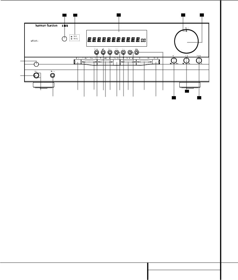
Front Panel Controls
27 |
26 |
25 |
24 |
23 |
MUTE T-MON |
AUTO TUNED ST |
MEMORY PRESET |
|
|
SLEEP |
1 |
|
|
|
2 |
|
|
|
3 |
5 |
7 |
9 ! |
4 |
6 |
8 |
) |
VMAx |
|
|
VMAx |
# % |
|
@ $ |
^ |
& |
( |
21 |
* |
20 |
22 |
1 Main Power Switch |
) Tuning Button |
( Sleep Button |
2 System Power Control |
! Tape Input Selector |
Ó Bass Control |
3 Power Indicator |
@ Preset Scan |
Ô Treble Control |
4 Headphone Jack |
# CD Input Selector |
Balance Control |
5 Mute |
$ Aux Input Selector |
Ò Volume Control |
6 Speaker 1 Selector |
% Preset Selector |
Ú Volume/Mute Indicator |
7 Speaker 2 Selector |
^ VMAx Selector |
Û Main Information Display |
8 Phono Input Selector |
& FM/AM Selector |
Ù Speaker Selection Indicators |
9 T-Mon (Tape Monitor) Input Selector |
* FM Mode Selector |
ı Remote Sensor Window |
1 Main Power Switch: Press this button to apply power to the HK 3470. When the switch is pressed in, the unit is placed in a Standby mode, as indicated by the Power Indicator 3 surrounding the System Power Control 2. This button MUST be pressed in to operate the unit. To turn the unit off and prevent the use of the remote control, this switch should be pressed until it pops out from the front panel so that the word “OFF” may be read at the top of the switch.
NOTE: In normal operation this switch is left in the “ON” position.
2 System Power Control: When the Main Power Switch 1 is “ON,” press this button to turn on the HK 3470; press it again to turn the unit off. Note that the Power Indicator
3surrounding the switch will turn green when the unit is on.
3Power Indicator: This LED will light in amber when the unit is in the Standby mode to signal that the unit is ready to be turned on. When the unit is in operation, the indicator will briefly turn red, and then change to green. A red indicator during normal operation means that the unit is in the Protect mode, and should be turned off and then checked for a possible speaker-wire short circuit.
4 Headphone Jack: This jack may be used to listen to the HK 3470’s output through a pair of headphones. Be certain that the headphones have a standard 1⁄4" stereo phone plug.
5 Mute: Press this button to momentarily silence the speaker output of the HK 3470.
6 Speaker 1 Button: Press this button to turn the speakers connected to the Speaker 1 output terminals ‡ on or off.
7 Speaker 2 Button: Press this button to turn the speakers connected to the Speaker 2 output terminals ° on or off.
5 FRONT PANEL CONTROLS
Front Panel Controls
8 Phono Input Selector: Press this button to select the output of a turntable that is connected to the Phono inputs §.
9T-Mon (Tape Monitor) Input Selector:
Press this button to listen to the output of a tape recorder connected to the Tape Monitor inputs ª. The T-Mon indicator will light to indicate that the input source is being monitored when the HK 3470 is connected to a three-head tape deck or another unit with offhead playback.
)Tuning Button: Press the left side of the button to tune lower-frequency stations and the right side of the button to tune higher-frequency stations. When a station with a strong signal is tuned, the TUNED indicator will light in the
Main Information Display Û. A brief (1/2 second) press of the button will manually tune to the next frequency increment, while pressing and holding the button for a longer period will automatically tune to the next station with a signal strong enough for acceptable reception.
!Tape Input Selector: Press this button to listen to the output of a tape recorder or other device connected to the Tape 2 inputs ⁄.
@ Preset Scan: Press this button to automatically scan through the stations that have been programmed in the HK 3470’s memory.
The tuner will play five seconds of each station before moving to the next preset station. To stop the scan when the desired station is heard, press the button again. (See page 15 for more information on the tuner memory system.)
# CD Input Selector: Press this button to listen to the output of a CD player connected to the CD inputs ¶.
$Aux Input Selector: Press this button to listen to the output of a device connected to the Aux inputs •.
% Preset Selector: Press this button to step up or down through the list of stations that has been entered into the preset memory. (See page 15 for more information on tuner programming.)
^VMAx Selector: Press this button to engage VMAx processing of a stereo input. The
VMAx Mode Indicator A will light, and you will notice a wider, more spacious sound field. In order to obtain maximum benefit, you should
be seated midway between the two loudspeakers, and the same distance from the speakers as the speakers are from each other. The speakers must be placed facing parallel and evenly with each other so that their baffles are in the same plane. Press the button again to return to Stereo mode.
& FM/AM Selector: Press this button to select the tuner as the input to the receiver. When the tuner is in use, press this button to change between the AM and FM frequency bands.
* FM Mode Selector: Press this button to select the Stereo or Mono mode for FM tuning. In the STEREO mode, a Stereo indicator will light in the Main Information Display Û, and stereo reception will be provided when stations are transmitting stereo signals. In the MONO mode, the left and right signals from stereo broadcasts will be mixed together and reproduced through all channels. Select MONO for better reception of weak signals. VMAx will have no effect in MONO mode.
( Sleep Button: Press this button to place the unit in the Sleep mode. Each press of the button selects the amount of time that will remain before the unit automatically goes into the Standby mode, as shown in the Main Information Display Û, in the following order:
|
|
|
90 |
|
80 |
|
|
70 |
|
60 |
|
50 |
|
|||
|
|
|
min |
|
|
min |
|
min |
|
|
min |
|
|
min |
|
|
|
|
|
|
|
|
|
|
|
|
|
|
|
|
|
|
|
|
|
40 |
|
|
30 |
|
|
20 |
|
|
10 |
|
|
OFF |
||
|
|
|
min |
|
|
min |
|
min |
|
|
min |
|
|
|||
|
|
|
|
|
|
|
|
|
|
|
|
|||||
Ó Bass Control: Turn this control to modify the low-frequency output of the left and right channels by as much as ±10dB. Set this control to a suitable position for your taste and room acoustics.
ÔTreble Control: Turn this control to modify the high-frequency output of the left and right channels by as much as ±10dB. Set this control to a suitable position for your taste and room acoustics.
Balance Control: Turn this control to change the relative volume for the left and right channels.
ÒVolume Control: Turn the knob clockwise to increase volume, counterclockwise to decrease the volume.
ÚVolume/Mute Indicator: This indicator will glow green when the HK 3470 is turned on. Its position will enable you to judge the relative volume of the unit even when the speakers are muted or turned off. When the indicator is pointing toward the left, as in an “8 o’clock” position, the volume is low; when it is pointing to the right, as in a “3 o’clock” position, the volume is loud. When the unit has been muted by pressing the Mute button 5, the indicator will flash.
Û Main Information Display: This display delivers messages and status indications to help you operate the receiver.
Ù Speaker Selection Indicators: These indicators light as a green LED next to the designation for each speaker pair to show when they are active. Press the Speaker 1 6 or
Speaker 2 7 Selectors to activate either pair of speakers. Both sets of speakers may be selected simultaneously as long as all speakers have a nominal impedance of 8 ohms or greater. However, occasionally the actual impedance will vary, depending upon the program material. If the impedance drops to a point where there may be potential damage to the equipment, the HK 3470 will go into protect mode.
ı Remote Sensor Window: The sensor behind this window receives infrared signals from the remote control. Aim the remote at this area and do not block or cover it unless an external remote sensor is installed.
6 FRONT PANEL CONTROLS
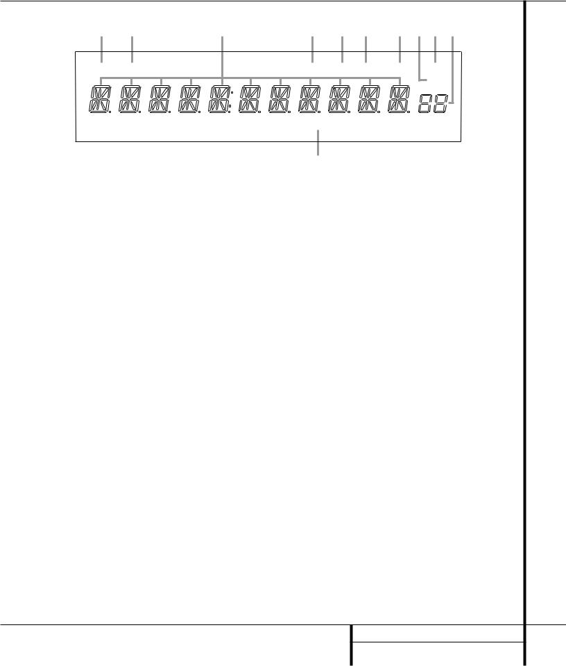
Front Panel Information Display
K |
J |
I |
H |
G F |
E D C B |
MUTE |
T-MON |
|
AUTO |
TUNED ST |
MEMORY PRESET |
|
|
|
|
|
SLEEP |
|
|
|
VMAx |
|
|
|
|
|
A |
|
|
A VMAx Mode Indicator |
|
E Memory Indicator |
|
I Main Information Display |
|
B Preset Number/Sleep Timer |
F Stereo Indicator |
|
J Tape Monitor (T-Mon) Indicator |
||
C Preset Indicator |
|
G Tuned Indicator |
|
K Mute Indicator |
|
D Sleep Indicator |
|
H Auto Indicator |
|
|
|
AVMAx Mode Indicator: This indicator lights when the VMAx mode is in use. (See page 14 for a description of the VMAx Mode.)
B Preset Number/Sleep Timer: When the tuner is in use, these numbers indicate the specific preset memory location in use. (See page 15 for more information on preset stations.) When the Sleep function is in use, these numbers show how many minutes remain before the unit goes into the Standby mode.
C Preset Indicator: This indicator lights when the tuner is in use to show that the
Preset Number/Sleep Timer B is showing the station’s preset memory number. (See page 15 for more information on tuner presets.)
D Sleep Indicator: This indicator lights when the Sleep function is in use. The numbers in the Preset Number/Sleep Timer Indicators will show the minutes remaining before the HK 3470 goes into the Standby mode. (See page 14 for more information on the Sleep function.)
E Memory Indicator: This indicator flashes when entering presets and other information into the tuner’s memory.
F Stereo Indicator: This indicator lights when an FM station is being tuned in stereo.
G Tuned Indicator: This indicator lights when a station is being received with sufficient signal strength to provide acceptable listening quality.
HAuto Indicator: This indicator lights when the tuner’s Auto mode is in use.
I Main Information Display: This display shows messages relating to the status, input source, tuner or other aspects of the HK 3470’s operation.
JTape Monitor (T-Mon) Indicator: When used with three-head cassette decks, or other recording devices that offer immediate playback of the recording as it is being made, the
HK 3470 allows you to monitor a recording rather than merely listening to the input source, or waiting until the recording session is complete in order to hear the recording. Press the
Tape Monitor Input Selector 9ç, and the
T-Mon Indicator J will light to remind you that you are monitoring the recording. Press the
Tape Monitor Input Selector 9ç again to hear the input source.
K Mute Indicator: This indicator lights to remind you that the HK 3470’s output has been silenced by pressing the Mute button 5®. Press the Mute button again to return to the previously selected output level.
7 FRONT PANEL INFORMATION DISPLAY
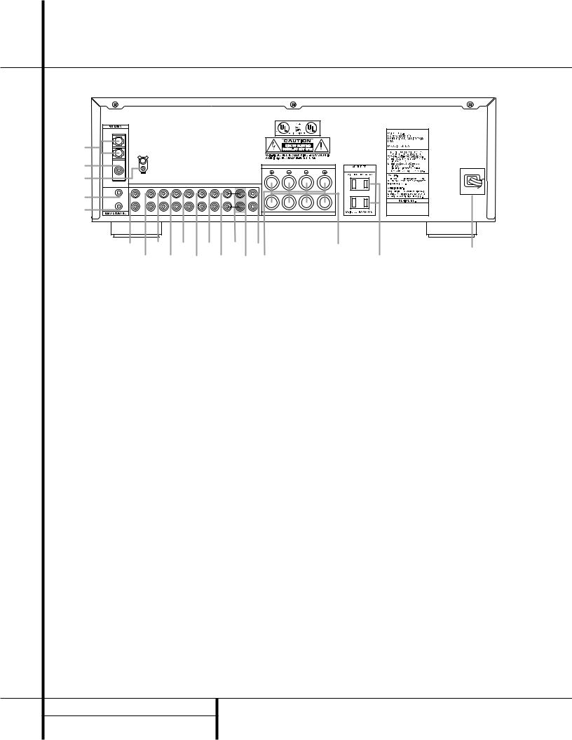
Rear Panel Connections |
|
|
|
|
|
|
|
|
|
|||||
|
|
|
|
|
|
|
|
|
|
|
|
|
|
HK3470 |
¡ |
AM |
|
|
|
|
|
|
|
|
|
|
|
|
|
LOOP |
|
|
|
|
|
|
|
|
|
|
|
|
|
|
|
|
|
|
|
|
|
|
|
|
|
|
|
|
|
™ |
FM |
|
|
|
|
|
|
|
|
S P E A K E R 1 ( 8 O h m s ) |
|
(120V, 60Hz) |
|
|
|
|
|
|
|
|
|
|
|
|
|
AC 120V 60HZ |
|||
£ |
75 Ω |
GND |
|
|
|
|
|
|
RIGHT |
LEFT |
|
|
|
|
|
|
|
|
|
|
|
|
|
|
|
|
|
||
|
|
|
|
|
|
|
|
|
|
|
|
|
|
|
|
PHONO |
CD |
AUX |
TAPE MON. |
|
TAPE 2 |
MAIN IN PRE OUT SUB OUT |
|
|
|
|
|
||
|
IN |
|
|
|
|
|
|
|
L |
|
|
|
|
400W |
¢ |
|
|
|
|
|
|
|
|
|
|
|
|
||
|
|
|
|
|
|
|
|
|
|
|
|
|
|
|
∞ |
OUT |
|
|
|
|
|
|
|
R |
|
|
|
|
|
IN |
IN |
IN |
PLAY REC. OUT |
PLAY |
REC. OUT |
|
MONO |
S P E A K E R 2 ( 8 O h m s ) |
|
|
|
|
||
|
§ |
|
• |
|
‚ |
¤ |
› |
fl |
|
° |
|
|
a |
|
|
|
¶ |
|
ª |
⁄ |
‹ |
fi ‡ |
|
|
|
· |
|||
|
|
|
|
|
|
|
||||||||
¡ AM Antenna |
|
|
|
|
|
|
• Aux Inputs |
|
|
|
|
fi Preamp Out |
||
™ FM Antenna |
|
|
|
|
|
|
ª Tape Monitor Play/In |
|
|
|
fl Subwoofer Out |
|||
£ Phono Ground |
|
|
|
|
|
|
‚ Tape Monitor Record/Out |
|
|
|
‡ Speaker 1 Terminals |
|||
¢ Remote IR In |
|
|
|
|
|
|
⁄ Tape 2 Play/In |
|
|
|
|
° Speaker 2 Terminals |
||
∞ Remote IR Out |
|
|
|
|
|
|
¤ Tape 2 Record/Out |
|
|
|
· Accessory Outlets |
|||
§ Phono Inputs |
|
|
|
|
|
|
‹ Main In |
|
|
|
|
a Power Cable |
||
¶ CD Inputs |
|
|
|
|
|
|
|
› Pre-Out/Main-In Jumper Pins |
|
|
|
|
||
8 REAR PANEL CONNECTIONS |
|
|
|
|
|
|
|
|
|
|||||
 Loading...