


Harman Kardon
AVR85
Audio/VideoReceiver
|
|
|
|
|
|
|
|
|
|
|
|
|
|
|
|
|
Volume |
|
|
AL |
TV DVD V1 |
V2 |
V3 |
|
TEST MEMO |
AUTO |
TUNED |
STEREO |
|
|
|
|
|
|
|
|
|||
|
|
|
|
|
|
|
|
|
|
|
dB |
|
|
|
|
|
|
|
|
|
|
|
|
|
|
|
|
|
|
|
kHz |
|
|
|
|
|
|
|
|
PCM |
|
|
|
|
|
|
|
|
|
|
MHz |
|
|
|
|
|
|
|
|
GITAL |
PRO•LOGIC 3•STEREO MOVIE |
RF |
OPT |
COAX |
MULTI NIGHT |
LFE |
ATT |
|
|
|
|
|
|
|
|
||||
O |
HALL |
MATRIX |
|
|
|
|
|
SLEEP |
P-SCAN |
DISP |
|
|
|
|
|
|
|
|
|
|
MULTI |
OSD |
ATT |
|
MEMO |
|
CLR |
MODE |
|
P•SET |
|
P•SCN |
TUNE |
MUTE |
|
|
|||
ode |
|
|
|
|
|
|
|
|
|
|
Bass |
|
Treble |
|
Balance |
|
VIDEO3 |
|
|
|
|
|
|
|
|
|
|
|
Min |
|
Max |
Min |
Max |
L |
R |
Video |
L Audio |
R |
|
|
|
|
|
|
|
|
|
|
|
|
|
|
|
|
|
|
|||
Owner’s Manual

Staple or clip original invoice here. ▼

Owner’s Manual
AVR85 Audio/Video Receiver
Table of Contents
Introduction . . . . . . . . . . . . . . . . . . . . . . . . . . . . . . . . . . 1
Safety Information . . . . . . . . . . . . . . . . . . . . . . . . . . . 2–3
Unpacking and Installation . . . . . . . . . . . . . . . . 3
Front Panel Controls. . . . . . . . . . . . . . . . . . . . . . . . . . 4–5
Front Panel Information Display . . . . . . . . . . . . . . . . 6–7
Rear Panel Connections . . . . . . . . . . . . . . . . . . . . . . . 8–9
Remote Control Functions . . . . . . . . . . . . . . . . . . . 10–12
Installation, Setup and Configuration . . . . . . . . . . 13–14
Remote Control Programming and Operation . . . 15–16
System Configuration . . . . . . . . . . . . . . . . . . . . . . . 17–20
Basic Operation. . . . . . . . . . . . . . . . . . . . . . . . . . . . 21–24
Source Selection . . . . . . . . . . . . . . . . . . . . . . . . 21
Surround Mode Selection . . . . . . . . . . . . . . . . . 21
Digital Audio Sources . . . . . . . . . . . . . . . . . . . . 22
Tuner Operation . . . . . . . . . . . . . . . . . . . . . 22–24
On-Screen Display. . . . . . . . . . . . . . . . . . . . . . . . . . 25–27
Advanced Features. . . . . . . . . . . . . . . . . . . . . . . . . . 28–31
Audio Tape Dubbing . . . . . . . . . . . . . . . . . . . . . 28
Delay Time Adjust. . . . . . . . . . . . . . . . . . . . 28–29
Digital Audio Playback. . . . . . . . . . . . . . . . 29–30
Surround Mode Chart . . . . . . . . . . . . . . . . . . . . 31
Multiroom Operation . . . . . . . . . . . . . . . . . . . . . . . 32–34
Troubleshooting Guide . . . . . . . . . . . . . . . . . . . . . . . . . 35
Technical Specifications . . . . . . . . . . . . . . . . . . . . . . . . 36
80 Crossways Park West
Woodbury, NY 11797
www.harmankardon.com
©1997 Harman Kardon, Incorporated

Introduction
1
Congratulations! With the purchase of a Harman Kardon AVR85 you are about to begin many years of listening enjoyment. The AVR85 has been custom designed to provide all the excitement and detail of movie sound tracks and every subtle nuance of musical selections. With on board Dolby* Digital Decoding, the AVR85 delivers six discrete channels of audio that take advantage of the digital sound tracks from the latest DVD and LV releases.
While complex digital systems are hard at work within the AVR85 to make all of this happen, hook-up and operation are simple. Color-keyed connections, a comprehensive remote control and on-screen menus make the AVR85 easy to use.To obtain the maximum enjoyment from your new receiver we urge you to take a few minutes to read through this manual. This will ensure that connections to speakers, source playback units and other external devices are made properly. In addition, a few minutes spent learning the functions of the various controls will enable you to take advantage of all the power the AVR85 is able to deliver.
If you have any questions about this product, its installation or operation, please contact your retailer or custom installer. They are your best local source of information.
Description and Features
The AVR85 is a full-featured A/V receiver, incorporating a wide variety of listening options. In addition to Dolby Digital decoding, Dolby Pro Logic* and Dolby 3 Stereo are available for compatibility with the tens of thousands of movies and television programs encoded with analog surround information. A choice of Hall, Matrix and Movie modes is also available for use with both encoded sources and traditional two-channel stereo recordings.
A total of five audio/video inputs, each with both composite and S-Video, as well as three additional audio only inputs are selected through a learning remote control and an easy to read front panel display or on-screen graphics through a TV monitor. Multiroom operation is available with independent source and volume selection.
The AVR85’s powerful amplifier uses traditional Harman Kardon High Current design philosophies to meet the wide dynamic range of any program selection.
Harman Kardon invented the highfidelity receiver over forty years ago. With state-of-the-art circuitry and timehonored circuit designs, the AVR85 is undoubtedly the finest receiver ever offered by Harman Kardon.
■On-Board Dolby Digital Decoding
■Coax, Optical or RF Digital Inputs
■On-Screen Menu Displays
■Learning Remote Control
■Composite and S-Video Switching
■Complete Multiroom Control
■Preamp Output for ALL Channels Permits Ease of Expansion
Safety Information
2
Important Safety Information
Verify Line Voltage Before Use
Your AVR85 has been designed for use with 120-volt AC current. Connection to a line voltage other than that for which it is intended can create a safety and fire hazard, and may damage the unit.
If you have any questions about the voltage requirements for your specific model, or about the line voltage in your area, contact your selling dealer before plugging the unit into a wall outlet.
Do Not Use Extension Cords
To avoid safety hazards, use only the power cord attached to your unit. We do not recommend that extension cords be used with this product. As with all electrical devices, do not run power cords under rugs or carpets or place heavy objects on them. Damaged power cords should be replaced immediately with cords meeting factory specifications.
Handle the AC Power Cord Gently
When disconnecting the power cord from an AC outlet, always pull the plug, never pull the cord. If you do not intend to use the unit for any considerable length of time, disconnect the plug from the AC outlet.
Do Not Open The Cabinet
There are no user-serviceable components inside this product. Opening the cabinet may present a shock hazard, and any modification to the product will void your guarantee. If water or any metal object such as a paper clip, wire or a staple accidentally falls inside the unit, disconnect it from the AC power source immediately, and consult an authorized service station.
CATV or Antenna Grounding
If an outside antenna or cable system is connected to this product, be certain that it is grounded so as to provide some protection against voltage surges and static charges. Section 810 of the National Electrical Code, ANSI/NFPA No. 70-1984, provides information with respect to proper grounding of the mast and supporting structure, grounding of the leadin wire to an antenna discharge unit, size of grounding conductors, location of antenna discharge unit, connection to grounding electrodes and requirements of the grounding electrode.
NOTE TO CATV SYSTEM INSTALLER:
This reminder is provided to call the CATV (Cable TV) system installer’s attention to article 820-40 of the NEC that provides guidelines for proper grounding and, in particular, specifies that the cable ground shall be connected to the grounding system of the building, as close to the point of cable entry as possible.
Installation Location
■To assure proper operation, and to avoid the potential for safety hazards, place the unit on a firm and level surface. When placing the unit on a shelf, be certain that the shelf and any mounting hardware can support the weight of the product.
■Make certain that proper space is provided both above and below the unit for ventilation. If this product will be installed in a cabinet or other enclosed area, make certain that there is sufficient air movement within the cabinet. Under some circumstances a fan may be required.
■Do not place the unit directly on a carpeted surface.
■Avoid installation in extremely hot or cold locations, or an area that is exposed to direct sunlight or heating equipment.
■Avoid moist or humid locations.
■Do not obstruct the ventilation slots on the top of the unit, or place objects directly over them.
CAUTION
RISK OF ELECTRIC SHOCK
DO NOT OPEN
CAUTION: TO REDUCE THE RISK OF ELECTRIC SHOCK, DO NOT REMOVE COVER (OR BACK). NO USER-SERVICEABLE PARTS INSIDE. REFER SERVICING TO QUALIFIED SERVICE PERSONNEL.
The lightning flash with arrowhead |
The exclamation point within an |
symbol, within an equilateral triangle, is |
equilateral triangle is intended to |
intended to alert the user to the |
alert the user to the presence of |
presence of uninsulated “dangerous voltage” |
important operating and maintenance |
within the product’s enclosure that may be of |
(servicing) instructions in the literature |
sufficient magnitude to consittute a risk of |
accompanying the appliance. |
electric shock to persons. |
|
WARNING: TO REDUCE THE RISK OF FIRE OR ELECTRIC SHOCK, DO NOT EXPOSE THIS APPLIANCE TO RAIN OR MOISTURE.
CAUTION: TO PREVENT ELECTRIC SHOCK, MATCH WIDE
BLADE OF PLUG TO WIDE SLOT, FULLY INSERT.
ATTENTION: POUR EVITER LES CHOCS ELECTRIQUES, INRODUIRE LA LAME LA PLUS LARGE DE LA FICHE DANS LA BORNE CORRESPONDANTE DE LA PRISE ET POUSSER JUSQU'AU FOND.

Safety Information
3
Cleaning
When the unit gets dirty, wipe it with a clean, soft dry cloth. If necessary, wipe it with a soft cloth dampened with mild soapy water, then a fresh cloth with clean water. Wipe dry immediately with a dry cloth. NEVER use benzene, aerosol cleaners, thinner, alcohol or any other volatile cleaning agent. Do not use abrasive cleaners, as they may damage the finish of metal parts. Avoid spraying insecticide near the unit.
Moving The Unit
Before moving the unit, be certain to disconnect any interconnection cords with other components, and make certain that you disconnect the unit from the AC outlet.
Important information for the user
NOTE: This equipment has been tested and found to comply with the limits for a Class B digital device, pursuant to Part 15 of the FCC Rules. The limits are designed to provide reasonable protection against harmful interference in a residential installation. This equipment generates, uses and can radiate radio frequency energy and, if not installed and used in accordance with the instructions, may cause harmful interference to radio communication. However, there is no guarantee that harmful interference will not occur in a particular installation.
If this equipment does cause harmful interference to radio or television reception, which can be determined by turning the equipment off and on, the user
is encouraged to try to correct the interference by one or more of the following measures:
■Reorient or relocate the receiving antenna.
■Increase the separation between the equipment and receiver.
■Connect the equipment into an outlet on a circuit different from that to which the receiver is connected.
■Consult the dealer or an experienced radio/TV technician for help.
This device complies with Part 15 of the FCC Rules. Operation is subject to the following two conditions: (1) this device may not cause harmful interference, and
(2) this device must accept interference received, including interference that may cause undesired operation.
NOTE: Changes or modifications may cause this unit to fail to comply with Part 15 of the FCC Rules and may void the user’s authority to operate the equipment.
Unpacking and Installation
The carton and shipping materials used to protect your new receiver during shipment were specially designed to cushion it from shock and vibration. We suggest that you save the carton and packing materials for use in shipping if you move or should the unit ever need repair.
To minimize the size of the carton in storage, you may wish to flatten it. This is done by carefully slitting the tape seams on the bottom and collapsing the carton down to a more two-dimensional appearance. Other cardboard inserts may be stored in the same manner. Packing materials that cannot be collapsed should be saved along with the carton in a plastic bag.
If you do not wish to save the packaging materials, please note that the carton and other sections of the shipping protection are recyclable. Please respect the environment and discard those materials at a local recycling center.
Typographic Conventions
In order to help you use this manual with the remote control, front panel controls, rear panel connections and on-screen menus, certain conventions have been used.
EXAMPLE – (bold type) indicates a specific remote control or front panel button, or rear panel connection jack
EXAMPLE – (OCR type) indicates a message that is visible through the onscreen menu system
1– (number in a square) indicates a specific front panel control
a– (number in an oval) indicates a button or indicator on the remote
¡– (number in a circle) indicates a rear panel connection
A– (letter in a square) indicates an indicator in the front panel display
Front Panel Controls
|
|
|
|
|
|
|
|
|
|
|
4 |
|
|
|
|
|
|
|
|
|
|
|
|
|
|
|
|
˜ |
|
|
|
|
|
|
ˆ |
|
|
|
|
|
|
|
|
|
ı |
|
|
|
|
|
AVR 85 |
|
|
|
|
|
|
|
|
|
|
|
|
|
|
|
|
|
|
|
|
|
|
|
|
|
|
|
|
|
|
|
|
|
|
|
|
|
|
|
|
|
Volume |
|
|
|
|
|
|
|
|
|
|
|
VISUAL |
TV DVD V1 |
V2 |
V3 |
TEST MEMO |
AUTO TUNED |
STEREO |
|
|
|
|
|
|
|
|
|
|
|
|
|
|
|
|
|
|
|
|
|
|
|
|
dB |
|
|
|
|
|
|
|
|
|
|
|
|
|
|
|
|
|
|
|
|
|
|
|
kHz |
|
|
|
|
|
|
|
|
|
|
|
|
|
|
|
|
AC-3 PCM |
|
|
|
|
|
|
MHz |
|
|
|
|
|
|
|
|
|
|
|
|
|
|
|
|
DIGITAL |
PRO•LOGIC 3•STEREO MOVIE |
RF OPT COAX MULTI NIGHT |
LFE |
ATT |
|
|
|
|
|
|
|
|||
|
|
|
|
|
|
|
|
|
STEREO |
HALL |
MATRIX |
|
|
SLEEP P-SCAN |
DISP |
|
|
|
|
|
|
|
|
|
AM•FM |
CD |
T•MON |
T•2 |
TV |
DVD |
V1 |
V2 |
V3 |
MULTI |
OSD |
ATT |
MEMO |
CLR |
MODE |
P•SET |
|
P•SCN |
TUNE |
MUTE |
|
|
|
|
|
|
|
|
|
Digital Input |
|
|
Mode |
|
|
|
|
|
|
Bass |
Treble |
|
Balance |
|
VIDEO3 |
|
|
Power |
Phones |
|
Night |
RF |
OPT |
|
Coax |
|
|
|
|
|
|
|
|
|
|
|
|
|
|
|
|
|
|
|
|
|
|
|
|
|
|
|
|
|
|
Min |
Max |
Min |
Max |
L |
R |
Video |
L Audio |
R |
|
|
|
|
|
|
|
|
|
|
|
|
|
|
|
|
|
|
|
|
|
|
|||
|
2 4 68 |
|
|
) @ $ ^ * Ó Ú |
|
|
Ù |
||||||||||||||||
1 3 57 9 ! # % & ( Ô Ò |
|
Û |
|
||||||||||||||||||||
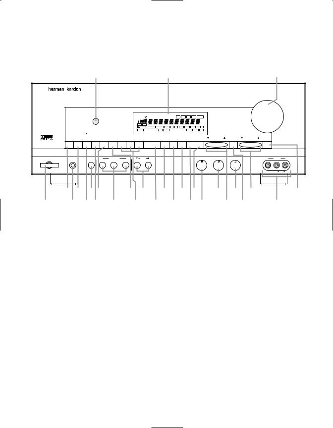
1Power |
!Video Sources |
ÔP-Set |
2AM/FM Tuner Mode Selector |
@Mode |
Balance |
3Headphone Jack |
#Multiroom Control |
ÒP-Scan |
4CD |
$OSD (On Screen Display) |
ÚTune |
5Tape1/Monitor |
%ATT (Attenuation) Mode Select |
ÛVideo 3 Input |
6Night Mode |
^Memo |
ÙMute |
7Tape 2 |
&Clear |
ıVolume Control |
8TV Input |
*FM Mode |
ˆInformation Display |
9Digital Input Selectors |
(Bass |
˜Remote Sensor Window |
)DVD Input |
ÓTreble |
|

1Power: Press this button once to turn the unit on and off. Once the unit is turned on, it may be turned off and then on again from the remote, if desired.
Note: When the remote is used to turn the unit off the LED surrounding the Power Switch will turn amber, indicating that the AVR85 is in a Standby mode. In this condition the unit is NOT disconnected from the AC main power supply.
2AM/FM Tuner Selector: Press this button once to select the tuner. Press it again to switch between AM and FM.
3Headphone Jack: Plug standard stereo headphones into this jack for private listening.
NOTE: When the headphones are in use the output to the speakers is muted and the surround mode is automatically switched to STEREO. When the headphones are removed from the jack, sound to the speakers is restored and the unit returns to the previous sound mode.
4CD: Press this button to select the CD player.
5Tape1/ Monitor: Press this button to select Tape One as the input source. A red LED above the button will illuminate to indicate that the Tape Monitor has been selected.
6Night Mode: Press this button to activate the “Night” mode, preventing loud playback when the digital modes are in use.
7Tape 2: Press this button to select Tape 2 input.
8TV Input: Press this button to select the source connected to the
TV Input ª.
9Digital Input Selectors: Press one of these buttons to select a digital input source. The digital audio source may be the same as, or different from, the analog audio of the selected video source.
Front Panel Controls
5
)DVD Input: Press this button to select the source connected to the DVD Input •. Note that if the DVD or LV player’s digital audio output is used, it must be selected separately using the Digital Input Selectors
9g.
!Video Sources: Press any of these buttons to select a video input source.
@Mode: Press these buttons to scroll up ⁄ or down ¤ through the list of available surround modes.
#Multiroom Control: Press the button to turn the remote room feed on or off. The Multi indicator Dwill light or flash when the remote feed is on. Note that the remote zone feed will remain on after the main room power is turned off until it is switched off by pressing this button again
$OSD (On Screen Display): Press the button briefly to display a system status report on your video screen.
%ATT (Attenuation) Mode Select:
Press this button to activate the Attenuation mode which cuts the analog input signal by 50% to compensate for high-level input sources.
^Memo: The memo button is used to enter stations to the tuner’s preset memory in either the manual or automatic modes.
&Clear: The clear button is used to cancel tuning, memory input or when clearing the unit’s memories.
*FM Mode: Press this button to select the tuning mode for FM stations.
(Bass: This knob adjusts the tone of low-frequency sounds. Turn it to the right to boost bass frequencies or to the left to cut bass frequencies.
ÓTreble: This knob adjusts
the tone of high-frequency sounds. Turn to it the right to boost high frequencies or to the left to cut high frequencies.
ÔP-Set: Press this button to manually scroll up ⁄ or down ¤ through the FM or AM stations programmed into the receiver’s preset memory.
Balance: This knob adjusts the balance between the front left and right speakers.
ÒP-Scan: Press this button to automatically scan through the FM or AM stations preset into the
receiver’s memory. Press the button again to stop the scan when the tuner is at the desired station.
ÚTune: Press this button to manually scan up ⁄ or down ¤ through the FM or AM bands.
ÛVideo 3 Input: Audio or Video sources connected to these jacks may be selected by pressing the
Video Source button !.
ÙMute: Press this button to cut the output to the speakers. Press it again to return to the previous volume level.
ıVolume Control: Turn the knob clockwise to increase volume, counterclockwise to decrease the volume. Note that approximately two revolutions of the knob are required to go from no output to maximum volume.
ˆInformation display: This display delivers messages and status indications to help you operate the receiver. Refer to the separate diagram for complete explanation of the FL display.
˜Remote Sensor Window: The sensor behind this window receives infrared signals from the remote control. Aim the remote at this area and do not block or cover it unless an external remote sensor is installed.
Front Panel Information Display
6
S |
R |
Q |
|
|
P O N M L |
|
||
VISUAL |
|
TV DVD V1 |
V2 |
V3 |
TEST MEMO AUTO TUNED STEREO |
|
||
|
|
|
|
|
|
|
dB |
|
|
|
|
|
|
|
|
kHz |
K |
AC-3 |
PCM |
|
|
|
|
|
MHz |
|
DIGITAL |
PRO•LOGIC 3•STEREO MOVIE RF OPT |
COAX MULTI NIGHT LFE ATT |
J |
|||||
STEREO |
|
HALL |
MATRIX |
|
|
SLEEP P-SCAN DISP |
|
|
A |
|
|
B |
|
|
C |
DEFGH I |
|
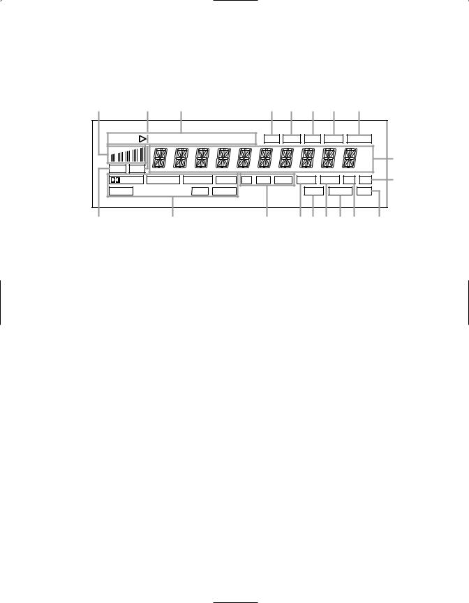
AAC-3 Indicator |
HLFE Indicator |
OMemo |
BSurround Mode Status |
IDISP |
PTest |
CDigital Mode Indicators |
JATT Indicator |
Q“Visual” Indicator |
DMulti |
KMain Information Display |
RPCM Indicator |
ESleep Indicator |
LStereo |
SSignal Level Indication |
FNight Indicator |
MTuned |
|
GP-Scan |
NAuto |
|

Front Panel Information Display
7
AAC-3 Indicator: This indicator illuminates when the AVR85 is decoding a Dolby Digital input source.
BSurround Mode Status: These indicators display the currently selected surround mode.
CDigital Mode Indicators: These indicators show which digital input is in use.
DMulti: This indicator signifies that the AVR85 is sending a program source to a remote room location. Note that it may be illuminated even when the unit is “off” in the main listening room, signifying that operation continues at another location. When a remote command is being received via the Multi IR connection b, this indicator will flash.
ESleep Indicator: This indicator lights when the AVR85 is in the Sleep mode.
FNight Indicator: This indicator lights when the AVR85 is in the Night mode, which prevents the AVR85 from loud playback when digital sources are in use.
GP-Scan: This indicator flashes when the stations programmed into the tuner memory are being automatically reviewed.
HLFE Indicator: This indicator will illuminate when the Low-Frequency Effects (LFE) option has been turned on through the controls in SETUP MENU 3.
IDISP: This indicator lights when the FL display has been turned
off using the Display button pto remind you that the unit is still turned on.
JATT Indicator: This indicator lights when the Attenuation function has been engaged to cut the input from analog sources by approximately 50%.
KMain Information Display: This ten-digit display shows messages relating to the status, input source, surround mode, tuner, volume level or other aspects of unit’s operation.
LStereo: This indicator lights when an FM station is broadcasting in stereo.
MTuned: This indicator lights when an AM or FM station is properly tuned and locked.
NAuto: This indicator signifies that the Automatic Tuning mode is in use for FM broadcasts.
OMemo: This indicator flashes when the Memo button is pressed when entering presets and other information into the tuner’s memory.
PTest: This indicator flashes when the output levels are being set using the built-in test signal generator.
Q“Visual” Indicator: These indicators display which input source is being fed to the video monitor output.
RPCM Indicator: This indicator illuminates to show that a standard PCM (SP/DIF) digital audio signal is being decoded by the digital-to- analog converter.
SSignal Level Indication: This is a visual indication of the strength of a radio station signal. The more bars visible, the stronger the station.

Rear Panel Connections
|
|
|
|
|
|
|
8 |
|
|
|
|
|
|
k j i h g fed c b a · ° |
|
‡ |
|
||||||
|
|
|
|
|
|
|
MULTI |
|
|
MODEL NO.: AVR85 |
AC 120V |
|
|
|
|
|
|
|
|
|
|
HARMAN KARDON |
|
|
|
|
|
|
|
|
|
AC-3 |
|
NORTHRIDGE |
60 Hz |
|
|
|
|
MULTI |
TV |
|
REMOTE |
|
CALIFORNIA, U.S.A. |
4.5 A |
|
|
|
|
|
OUT |
MONI |
|
CONT. |
RF IN |
|
|
|
|
|
|
|
OUT |
IN |
|
CENTER |
MADE IN JAPAN |
|
||
|
|
|
|
|
|
|
|
||||
|
ANTENNA |
|
|
|
|
|
|
|
|
|
|
|
|
|
|
|
|
|
AC-3/PCM |
|
SERIAL NO. |
|
|
|
|
|
|
OUT |
OUT |
|
|
COAXIAL |
8 OHMS |
|
|
|
|
|
|
|
|
|
|
||||
|
|
|
|
VIDEO2 |
VIDEO2 |
|
AC-3/PCM |
|
|
|
|
|
AM |
|
OUT |
IN |
IN |
PRE OUT |
|
|
|
|
|
¡ |
|
|
OPTICAL |
|
|
|
|||||
|
|
|
|
|
|
||||||
GND |
|
TAPE2 |
|
|
L |
R |
L |
SURR. |
|
|
|
|
|
IN |
OUT |
|
|
|
DIGITAL INPUT |
|
|
|
|
|
|
|
OUT |
|
FRONT |
|
8 OHMS |
AC OUTLETS (120V 60Hz) |
|
||
|
|
|
|
VIDEO1 |
VIDEO1 |
|
|
SWITCHED 120W 1.0A |
|
||
™ |
FM |
|
|
|
R |
|
|
||||
|
|
|
|
|
|
|
|
|
|||
(75Ω ) |
|
OUT |
IN |
IN |
|
SURR. |
|
|
|
|
|
£ |
|
|
TAPE1 |
|
|
|
|
|
|
|
|
|
|
|
|
|
|
|
|
|
|
||
|
|
IN |
DVD |
DVD |
|
SUB |
L |
FRONT |
UNSWITCHED 120W 1.0A |
|
|
¢ |
|
|
|
|
|
|
|
|
|
||
|
|
|
|
|
CENTER |
WOOFER |
|
8 OHMS |
|
|
|
|
|
CD |
TV |
TV |
|
|
|
|
|
||
|
|
|
|
|
|
|
|
||||
|
L |
R |
L |
R |
|
|
|
R |
|
|
|
|
|
|
|
|
|
|
|||||
§ |
|
|
AUDIO |
|
VIDEO |
S-VIDEO |
|
|
|
|
|
|
|
|
|
|
|
|
SPEAKERS |
|
|
|
|
¶ |
|
|
|
|
|
|
|
|
|
|
|
|
|
|
• |
ª |
|
‚ ⁄ |
¤ ‹ |
› fi |
fl |
||
¡ AM Antenna |
⁄ Subwoofer Pre-Out |
b Multi IR |
||
™ FM Antenna |
¤ Center |
c Remote IR In |
||
£ Tape 2 Out |
‹ Surround |
d Remote IR Out |
||
¢ Tape 2 |
In |
› Front |
e VCR 1 |
Inputs |
Tape 1 |
Out |
fi Switched AC Outlet |
f VCR 1 |
Outputs |
§ Tape 1 |
In |
fl Unswitched AC Outlet |
g TV Monitor S-Video Output |
|
¶ CD IN |
|
‡ Power Cable |
h TV Monitor Video Output |
|
• DVD Inputs |
° AC-3/PCM Optical Input |
i Multiroom Audio Outputs |
||
ª TV Inputs |
· AC-3/PCM Coaxial Input |
j VCR 2 |
Outputs |
|
‚ Pre-Outs |
a AC-3 RF Input |
k VCR 2 |
Inputs |
|

Rear Panel Connections
9
¡ AM Antenna: Connect the AM loop antenna supplied with the receiver to these terminals. If an external AM antenna is used, make connections to the AM and GND terminals in accordance with the instructions supplied with the antenna.
™ FM Antenna: Connect an indoor or external FM antenna to this terminal.
£Tape 2 Out: Connect these jacks to the RECORD/INPUT jacks of a second audio recorder.
¢Tape 2 In: Connect these jacks to the PLAY/OUT jacks of a second audio recorder.
Tape 1 Out: Connect these jacks to the RECORD/INPUT jacks of an audio recorder.
§Tape 1 In: Connect these jacks to the PLAY/OUT jacks of an audio recorder.
¶ CD IN: Connect these jacks to the output of a compact disc player or CD changer.
• DVD Inputs: Connect the analog audio outputs and composite S-Video output of a DVD or LV player to these jacks.
ªTV Inputs: Connect these jacks to the audio and video outputs of a TV Tuner, Cable TV converter box, satellite receiver, or any other audio/video source.
‚ Pre-Outs: If external power amplifiers are used for any channels, connect them to these jacks
⁄ Subwoofer Pre-Out: Connect this jack to the line level input of a powered subwoofer. If an external subwoofer amplifier is used, connect this jack to the subwoofer amplifier input.
¤ Center: Connect these terminals to the center speaker.
‹ Surround: Connect these terminals to the surround speakers.
› Front: Connect these terminals to the front speakers.
fi Switched AC Outlet: This outlet may be used to power any device that you wish to have on when the unit is turned on.
fl Unswitched AC Outlet: This outlet may be used to power any AC device. The power will remain on at this outlet regardless of whether the AVR85 is on or off.
NOTE: The power consumption of the device plugged into each of these outlets should not exceed 120 watts.
‡ Power Cable: Connect the AC plug to a non-switched AC wall output.
° AC-3/PCM Optical Input:
Connect the optical digital output from a DVD player, HDTV receiver, LV player or CD player to this jack. The signal may be either a Dolby Digital (AC-3) signal or a standard PCM digital source.
· AC-3/PCM Coaxial Input:
Connect the coax digital output from a DVD player, HDTV receiver, LV player or CD player to this jack. The signal may be either a Dolby Digital (AC-3) signal or a standard PCM digital source.
a AC-3 RF Input: Connect the AC-3 RF output of an LV player equipped for digital audio to this jack.
NOTE: Do not connect standard analog audio sources to these jacks.
b Multi IR: Connect the output of an IR sensor in a remote room to this jack to operate the AVR85’s multiroom control system.
c Remote IR In: If the AVR85’s front panel IR sensor is blocked due to cabinet doors or other obstructions, an external IR sensor may be used. Connect the output of the sensor to this jack.
d Remote IR Out: This connection permits the IR sensor in the receiver to serve other remote controlled devices. Connect this jack to the “IR IN” jack on Harman Kardon or other compatible equipment.
eVCR 1 Inputs: Connect these jacks to the audio, video and S-Video PLAY/OUT jacks of a VCR.
fVCR 1 Outputs: Connect these jacks to the audio, video and S-Video RECORD/IN jacks of a VCR.
gTV Monitor S-Video Output:
Connect this jack to the S-Video input of a TV monitor or video projector to view S-Video sources selected by the receiver’s video switcher.
NOTE: Standard (composite) video and S-Video signals will appear only at their respective output. The AVR85 does not convert one video format to another.
hTV Monitor Video Output:
Connect this jack to the standard (composite) video input of a TV monitor or video projector to view the on-screen menus and the output of any standard video source selected by the receiver’s video switcher.
i Multiroom Audio Outputs:
Connect these jacks to the optional audio power amplifier that powers remote room speakers with the input selected by the multiroom control system.
jVCR 2 Outputs: Connect these jacks to the audio, video and S-Video RECORD/IN jacks of a second VCR.
kVCR 2 Inputs: Connect these jacks to the audio, video and S-Video PLAY/OUT jacks of a second VCR.
 Loading...