


ENGLISH |
AVR 155 Audio/VideoReceiver |
OWNER’S MANUAL |
Table of Contents
3Introduction
4Safety Information
4Unpacking
5Front Panel Controls
7 Rear Panel Connections
9 Main Remote Control Functions
13Installation and Connections
13Audio Connections
13Video Connections
14HDMI Connections
14SCART A/V Connections
15Power Connections
16Speaker Selection
16Speaker Placement
17System Configuration
17First Turn On
17Using the On-Screen Display
17System Setup
18Input Setup
19Surround Setup
19Night Mode Settings
20Configuring the Surround Off (Stereo) Modes
21Automated Speaker Setup Using EzSet/EQ
23Manual Setup
23Speaker Setup
26Delay Settings
27 |
Output Level Adjustment |
30 |
Operation |
30 |
Surround Mode Chart |
32Basic Operation
32Source Selection
326-Channel Direct Input
32Controls and Use of Headphones
33Surround Mode Selection
33 Digital Audio Playback
33 Dolby Digital
33DTS
34PCM Audio Playback
34Selecting a Digital Source
34Digital Bitstream Indicators
34Surround mode Types
35Surround Mode Post Processing
35PCM Playback Indications
35Speaker/Channel Indicators
36Night Mode
37Tape Recording
37Output Level Adjustment With Source Signals
38Dim function
38Memory backup
39System Setup
39 Front Panel Display Fade
39Turn-On Volume Level
39Semi-OSD Settings
40Full-OSD Time Out Adjustment
40Default Surround Mode
40Full-OSD Background Color
41Tuner Operation
41 Basic Tuner Operation
41 Station Selection
41Preset Tuning
42RDS Operation
42 |
RDS Tuning |
42RDS Display Options
42Program Search (PTY)
43Programming the Remote
43 Programming the Remote with Codes
43 |
Direct Code Entry |
48 |
Troubleshooting Guide |
43 |
Auto Search Method |
48 |
Processor Reset |
43 |
Code Readout |
49 |
Technical Specifications |
44 |
Macro Programming |
50 |
Appendix - Settings Worksheet |
44Programmed Device Functions
44Volume Punch-Through
45Channel Control Punch-Through
45Transport Control Punch-Through
45Resetting the Remote Memory
46Function List
Declaration of Conformity
We, Harman Consumer Group, Inc.
2, route de Tours
72500 Château-du-Loir,
FRANCE
declare in own responsibility, that the product described in this owner’s manual is in compliance with technical standards:
EN 55013:2001 + A1:2003
EN 55020:2002 + A1:2003
EN 61000-3-2:2000
EN 61000-3-3:1995 + A1:2001
EN 60065:2002
Jurjen Amsterdam
Harman Consumer Group, Inc.
02/08
Typographical Conventions
In order to help you use this manual with the remote control, front-panel controls and rear-panel connections, certain conventions have been used.
EXAMPLE – (bold type) indicates a specific remote control or front-panel button, or rear-panel connection jack
EXAMPLE – (OCR type) indicates a message that is visible on the front-panel information display
1 – |
(number in a square) indicates a specific front-panel control |
– |
(number in a circle) indicates a rear-panel connection |
0 – (number in an oval) indicates a button or indicator on the remote
The appearance of the text or cursor for your receiver’s on-screen menus may vary slightly from the illustrations in this manual. Whether the text appears in all uppercase or upperand lowercase characters, performance and operation remain the same.
2 TABLE OF CONTENTS

Introduction
Thank you for choosing Harman Kardon!
With the purchase of a Harman Kardon AVR 155 you are about to begin many years of listening enjoyment. Designed to provide all the excitement and detail of movie soundtracks and every nuance of musical selections, the AVR is truly a multichannel receiver for the new millennium. In addition to the traditional 5.1 digital decoding modes such as Dolby Digital and DTS, it offers the latest advancements in surround technology such as Dolby Pro Logic II, the full suite of DTS modes, DTS Neo:6 and the latest 5.1 channel versions of Harman's own Logic 7 technology.
The AVR has been engineered so that it is easy to take advantage of all the power of its digital technology. On-screen menus, fully color coded connection jacks and terminals make installation fast and simple. However, to obtain the maximum enjoyment from your new receiver, we urge you to read this manual. A few minutes spent learning the functions of the various controls will enable you to take advantage of all the power the AVR is able to deliver.
If you have any questions about this product, its installation or its operation, please contact your retailer or custom installer. They are your best local sources of information.
Description and Features
The AVR 155 is among the most versatile and multifeatured A/V receivers available, incorporating a wide range of listening options. In addition to Dolby Digital and DTS decoding for digital sources, a broad choice of surround modes for Matrix surround-encoded or Stereo recordings are available for use with sources such as CD, VCR, TV broadcasts and the AVR’s own FM/AM tuner. Along with Dolby Digital, Dolby Pro Logic II, DTS Neo:6, DTS 96/24, Dolby 3 Stereo, 5 Channel Stereo and Hall and Theater modes, the AVR offers Harman International’s exclusive Logic 7 process in 5.1 versions to create a wider, more enveloping field environment and more defined fly-overs and pans.
Dolby Virtual Speaker is available to create enveloping sound fields from front left and right speakers, and the latest Dolby Headphone circuitry creates an amazing sense of openness with headphones.
In addition to providing a wide range of listening options, the AVR is easy to configure so that it provides the best results with your speakers and specific listening-room environment.
A Stereo-Direct mode bypasses the digital processor to preserve all of the subtleties of older analog, two-channel materials, while bass management, available in the surround and Stereo-Digital modes,improves your ability to tailor the sound to suit your room acoustics or taste.
The AVR 155 takes the “video” part of its name seriously. Along with three HDMI inputs and two 100MHz analog component video inputs, the
AVR 155 provides A/V sync delay so that the lip sync errors – commonly seen when digital video processing is used in a source, program or video display – are eliminated. For the ultimate in flexibility, the AVR features connections for three video devices, all with both composite and S-Video inputs. Two additional audio inputs are available, and a total of four digital inputs and two outputs make the AVR 155 capable of handling all the latest digital audio sources.
For compatibility with the latest HDTV video sources and progressive scan DVD players, the AVR also features wide-bandwidth, low-crosstalk component video switching.
Coax and optical digital outputs are available for direct connection to digital recorders. A video recording output and a color-coded six-channel input make the AVR 155 virtually future-proof, with everything needed to accommodate tomorrow’s new formats right on board.
An important addition to the AVR 155’s impressive list of features is EzSet/EQ™, which automates the configuration process to make it quicker, easier and more precise. Using the special microphone supplied with the unit, EzSet/EQ takes the guesswork out of entering speaker “size” and crossover information, delay times for all channels and output levels. In addition to the configuration settings, EzSet/EQ also includes room equalization so that the signals sent to each speaker are tailored to provide accurate sonic quality with your specific combination of speaker type, room size and other factors that influence room acoustics. With EzSet/EQ, your system is custom-configured in a few minutes with accuracy that previously required expensive and hard-to-use test equipment.
In tandem with EzSet/EQ, the AVR 155 includes a full set of manual configuration settings for those who wish to custom-trim their system even further. A Triple Crossover bass management system makes it possible to enter different crossover settings for each speaker group.
The AVR 155’s powerful amplifier uses traditional Harman Kardon high-current design technologies to meet the wide dynamic range of any program selection.
Harman Kardon invented the high-fidelity receiver more then fifty years ago. With state-of-the-art circuitry and time-honored circuit designs, the AVR 155 is the perfect combination of the latest in digital audio technology, a quiet yet powerful analog amplifier in an elegant, easy-to-use package.
νDolby* Digital, Dolby Pro Logic* II Decoding, and DTS®.
νFive channels of high-current amplification
νHarman Kardon’s exclusive Logic 7® processing, along with a choice of Dolby Virtual Speaker processing for use when only two speakers are available
νDolby Headphone to create spacious, open sound fields when using headphones
νHarman Kardon’s advanced EzSet/EQ™ automatically configures speaker settings and sets room equalization for quick, easy and accurate system setup
νThree HDMI 1.3 and two assignable high-bandwidth analog component inputs for compatibility with the latest high-definition video sources
νStereo-Direct Mode for Two-Channel Sources Bypasses DSP Processing to Preserve the Integrity of Analog Materials
νStereo-Digital Mode for Programmable Bass Management of Low Frequencies Between Main Speakers and Subwoofer
νFront panel analog A/V inputs
νFront panel digital inputs for easy connection to portable digital devices and the latest video game consoles
νInput titling for all input sources (except tuner)
νMultiple digital inputs and outputs
νOn-screen menu and display system with choice of blue or black background screen
νA/V Sync delay adjustable for each input delivers perfect lip sync with digital programs or video displays
ν6-Channel Direct Input for Use with Future Audio Formats
νExtensive bass management options, including three separate crossover groupings
νMain Remote with Internal Codes
INTRODUCTION 3
ENGLISH

Safety Information
Important Safety Information
READ THIS BEFORE OPERATING YOUR UNIT
Do not install this equipment in a confined space such as a case or similar – away from direct sunlight, heat sources, vibration, dust, moisture, and/or cold. Avoid installing this unit where foreign object may fall onto this unit and/or this unit may be exposed to liquid dripping or splashing. On the top of this unit, do not place:
–Burning objects (i.e. candles), as they may cause fire, damage to this unit, and/or personal injury.
–Containers with liquid in them, as they may fall and liquid may cause electrical shock to the user and/or damage to this unit.
Do not cover this unit with a newspaper, tablecloth, curtain, etc. in order not to obstruct heat radiation. If the temperature inside this unit rises, it may cause fire, damage to this unit, and/or personal injury.
Install this unit near the AC outlet and where the AC power plug can be reached easily.
This unit is not disconnected from the AC power source as long as it is connected to the wall outlet, even if this unit itself is turned off. This state is called the standby mode. In this state, this unit is designed to consume a very small quantity of power.
WARNING. TO REDUCE THE RISK OF FIRE OR ELECTRIC SHOCK, DO NOT EXPOSE THIS APPLIANCE TO RAIN OR MOISTURE.
Verify Line Voltage Before Use
Your AVR has been designed for use with 220-230-Volt AC current. Connection to a line voltage other than that for which it is intended can create a safety and fire hazard and may damage the unit. If you have any questions about the voltage requirements for your specific model, or about the line voltage in your area, contact your dealer before plugging the unit into a wall outlet.
Do Not Use Extension Cords
To avoid safety hazards, use only the power cord attached to your unit. We do not recommend that extension cords be used with this product. As with all electrical devices, do not run power cords under rugs or carpets or place heavy objects on them. Damaged power cords should be replaced immediately by an authorized service depot with a cord meeting factory specifications.
Handle the AC Power Cord Gently
When disconnecting the power cord from an AC outlet, always pull the plug, never pull the cord. If you do not intend to use the unit for any considerable length of time, disconnect the plug from the AC outlet.
Do Not Open the Cabinet
There are no user-serviceable components inside this product. Opening the cabinet may present a shock hazard, and any modification to the product will void your guarantee. If water or any metal object such as a paper clip, wire or a staple accidentally falls inside the unit, disconnect it from the AC power source immediately, and consult an authorized service station.
Installation Location
νTo assure proper operation and to avoid the potential for safety hazards, place the unit on a firm and level surface. When placing the unit on a shelf, be certain that the shelf and any mounting hardware can support the weight of the product.
νMake certain that proper space is provided both above and below the unit for ventilation. If this product will be installed in a cabinet or other enclosed area, make certain that there is sufficient air movement within the cabinet. Under some circumstances a fan may be required.
νDo not place the unit directly on a carpeted surface.
νAvoid installation in extremely hot or cold locations, or an area that is exposed to direct sunlight or heating equipment.
νAvoid moist or humid locations.
|
νDo not obstruct the ventilation slots on the top of the unit, or place objects directly over them.
νDue to the weight of the AVR 155 and the heat generated by the amplifiers, there is the remote possibility that the rubber padding on the bottom of the unit’s feet may leave marks on certain wood or veneer materials. Use caution when placing the unit on soft woods or other materials that may be damaged by heat or heavy objects. Some surface finishes may be particularly sensitive to absorbing such marks due to a variety of factors beyond
Harman Kardon's control, including the nature of the finish, cleaning materials used, and normal heat and vibration caused by the use of the product, or other factors. We recommend that caution be exercised in choosing an installation location for the component and in normal maintenance practices, as your warranty will not cover this type of damage to furniture.
Cleaning
When the unit gets dirty, wipe it with a clean, soft, dry cloth. If necessary, wipe it with a soft cloth dampened with mild soapy water, then a fresh cloth with clean water. Wipe dry immediately with a dry cloth. NEVER use benzene, aerosol cleaners, thinner, alcohol or any other volatile cleaning agent. Do not use abrasive cleaners, as they may damage the finish of metal parts. Avoid spraying insecticide near the unit.
Moving the Unit
Before moving the unit, be certain to disconnect any interconnection cords with other components, and make certain that you disconnect the unit from the AC outlet.
Unpacking
The carton and shipping materials used to protect your new receiver during shipment were specially designed to cushion it from shock and vibration. We suggest that you save the carton and packing materials for use in shipping if you move, or should the unit ever need repair.
To minimize the size of the carton in storage, you may wish to flatten it. This is done by carefully slitting the tape seams on the bottom and collapsing the carton. Other cardboard inserts may be stored in the same manner. Packing materials that cannot be collapsed should be saved along with the carton in a plastic bag.
If you do not wish to save the packaging materials, please note that the carton and other sections of the shipping protection are recyclable. Please respect the environment and discard those materials at a local recycling center.
It is important that you remove the protective plastic film from the front-panel lens. Leaving the film in place will affect the performance of your remote control.
4 SAFETY INFORMATION
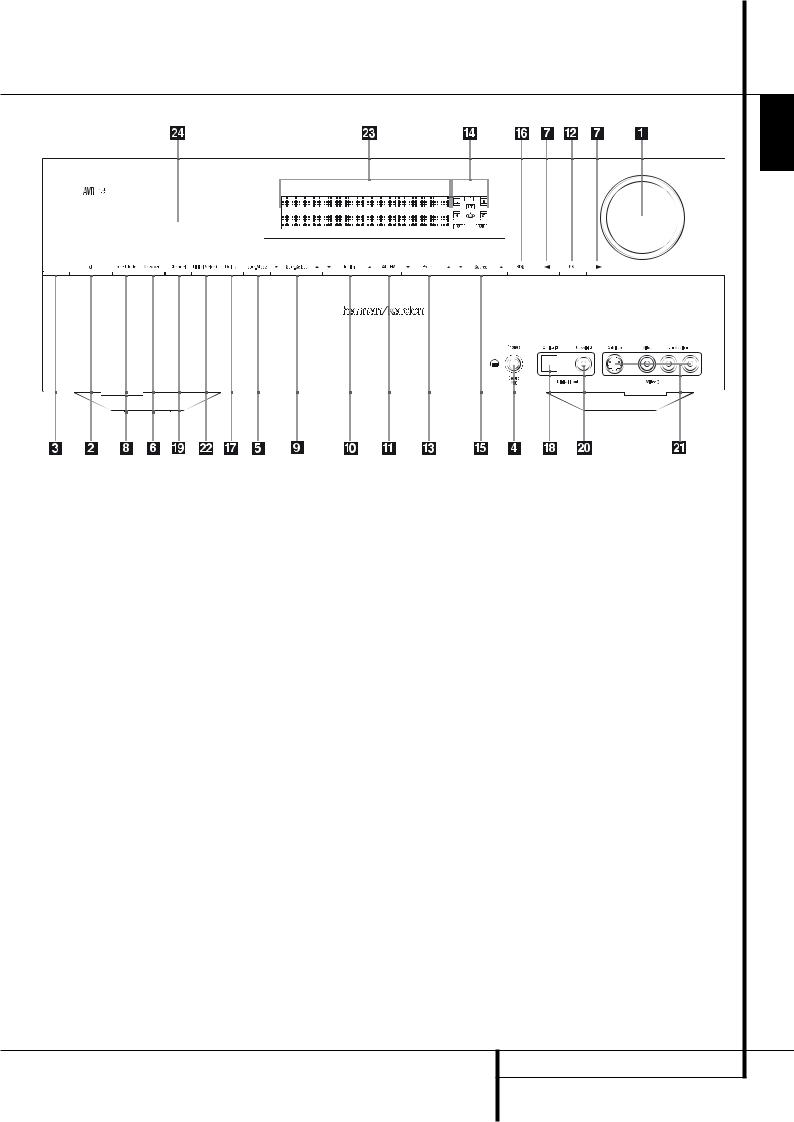
Front Panel Controls
ENGLISH
|
|
|
|
|
|
Ô Video 3 input jacks |
|
|
|
|
|
|
|
||
1 Volume Control |
! Tuner Band Selector |
||||||
2 System Power Control |
@ OK Button |
Digital Input Selector |
|||||
3 Power Indicator |
# Preset Stations Selector |
Ò Main Information Display |
|||||
4 Headphone Jack |
$ Speaker/Channel Input Indicator |
Ú Remote Sensor Window |
|||||
5 Surround Mode Group Selector |
% Input Source Selector |
|
|||||
6 Speaker Select Button |
^ RDS Select Button |
|
|||||
7 Selector Buttons |
& Delay |
|
|||||
8 Tone Mode |
* Digital Optical 3 Input |
|
|||||
9 Surround Mode Selector |
( Channel Select Button |
|
|||||
) Tuning Up/Down |
Ó Digital Coax 3 Input |
|
|||||
1 Volume Control: Turn this knob clockwise |
3 Power Indicator: This LED will be illuminated |
5 Surround Mode Group Selector: Press this |
|||||
to increase the volume, counterclockwise to |
in amber when the unit is in the Standby mode |
button to select the top-level group of surround |
|||||
decrease the volume. If the AVR is muted, adjust- |
to signal that the unit is ready to be turned on. |
modes. Each press of the button will select a |
|||||
ing volume control will automatically release the |
When the unit is in operation, the indicator will |
major mode grouping in the following order: |
|||||
unit from the silenced condition. |
turn white. |
Dolby Modes ‹ DTS Digital Modes ‹ DSP Modes |
|||||
|
|
|
|
|
|
||
2 System Power Control: When the Main |
4 Headphone Jack: This jack may be used to |
‹ Stereo Modes ‹ Logic 7 Modes |
|||||
Power Switch on the rear panel is “ON,” |
listen to the AVR’s output through a pair of head- |
Once the button is pressed so that the name of |
|||||
press this button to turn on the AVR; press it |
phones. Be certain that the headphones have a |
||||||
the desired surround mode group appears in the |
|||||||
again to turn the unit off (to Standby). Note that |
standard 6.3 mm stereo phone plug. Note that |
||||||
Main Information Display Ò, press the |
|||||||
the Power Indicator 3 will turn white when |
the speakers will automatically be turned off |
||||||
Surround Mode Selector 9 to cycle through |
|||||||
the unit is on. |
when the headphones are connected. |
||||||
the individual modes available. For example, press |
|||||||
|
|
|
|
|
|
||
|
|
|
When configuring your system using EzSet/EQ, |
this button to select Dolby modes, and then press |
|||
|
|
|
the calibration microphone should be plugged |
the Surround Mode Selector 9 to choose |
|||
|
|
|
into this jack 4 using the supplied adaptor that |
from the various mode options. |
|||
|
|
|
converts the small mini-plug at the end of the |
6 Speaker Select Button: Press this button |
|||
|
|
|
microphone’s cord to a 1/4" plug. |
||||
|
|
|
to begin the process of selecting the speaker |
||||
|
|
|
|
|
|
||
|
|
|
|
|
|
positions that are used in your listening room. |
|
|
|
|
|
|
|
(See page 17 for more information on setup and |
|
|
|
|
|
|
|
configuration.) |
|
FRONT PANEL CONTROLS 5

Front Panel Controls
7 Selector Buttons: When you are establishing the AVR’s configuration settings, use these buttons to select from the choices available, as shown in the Main Information Display Ò.
8 Tone Mode: Pressing this button enables or disables the Balance, Bass and Treble tone controls. When the button is pressed so that the words TONE IN appear in the Main Information Display Ò, the settings of the
Bass and Treble controls and of the Balance control will affect the output signals.
If you press 8 until TONE IN or TONE OUT appear in the Display, you can switch between these two functions with the Selector Buttons 7 the words TONE OUT appear in the Main Information Display Ò, the output signal will be “flat,” without any balance, bass or treble alteration.
9 Surround Mode Selector: Press this button to select from among the available surround mode options for the mode group selected. The specific modes will vary based on the number of speakers available, the mode group and if the input source is digital or analog. For example, press the Surround Mode Group Selector 5 to select a mode grouping such as Dolby or Logic 7, and then press this button to see the mode choices available. For more information on mode selection, see page 30.
) Tuning Selector: Press the left side of the button to tune lower frequency stations and the right side of the button to tune higher frequency stations. When a station with a strong signal is reached, MANUAL TUNED or AUTO TUNED will appear in the Main Information Display Ò (see page 41 for more information on tuning stations).
! Tuner Band Selector: Pressing this button will automatically switch the AVR to the Tuner mode. Pressing it again will switch between the AM and FM frequency bands, holding it pressed for some seconds will switch between stereo and mono receiving and between automatic and manual tuning mode (See page 41 for more information on the tuner).
@ OK Button: When making choices during the setup and configuration process, press this button to enter the desired setting as shown in the
Main Information Display Ò into the AVR’s memory.
# Preset Stations Selector: Press this button to scroll up or down through the list of stations that have been entered into the preset memory (See page 41 for more information on tuner programming).
$ Speaker/Channel Input Indicators: These indicators are multipurpose, indicating either the speaker type selected for each channel or the incoming data-signal configuration. The left, center, right, right surround and left surround speaker indicators are composed of three boxes, while the subwoofer is a single box. The center box lights when a “Small” speaker is selected, and the two outer boxes light when “Large” speakers are selected. When none of the boxes are lit for the center, surround or subwoofer channels, no speaker has been selected for that position. (See page 23 for more information on configuring speakers.) The letters inside each of the center boxes display active input channels. For standard analog inputs, only the L and R will light, indicating a stereo input. When a digital source is playing, the indicators will light to display the channels begin received at the digital input. When the letters flash, the digital input has been interrupted.
(See page 35 for more information on the Channel Indicators).
% Input Source Selector: Press this button to change the input by scrolling through the list of input sources.
^ RDS Select Button: Press this button to display the various messages that are part of the RDS data system of the AVR’s tuner.
(See page 42 for more information on RDS).
& Delay: Press this button to begin the sequence of steps required to enter delay time settings (See page 26 for more information on delay times).
* Digital Optical 3 Input: Connect the optical digital audio output of an audio or video product to this jack. The Input is protected by a spring-acti- vated closing flap, which opens when you insert an optical (TOS) plug and closes again when you remove it. You may hide this input and the one next to it with the supplied trim panel..
( Channel Select Button: Press this button to begin the process of trimming the channel output levels using an external audio source. (For more information on output level trim adjustment, see page 37).
Ó Digital Coax 3 Input: This jack is normally used for connection to the output of portable digital audio devices, video game consoles or other products that have a coax digital jack.
Ô Video 3 Input Jacks: These audio/video jacks may be used for temporary connection to video games or portable audio/video products such as camcorders and portable audio players.
Digital Input: When playing a source that has a digital output, press this button to select between the Optical (28) and Coaxial (24) digital inputs. (See pages 17 and 33 for more information on digital audio).
Ò Main Information Display: This display delivers messages and status indications to help you operate the receiver.
Ú Remote Sensor Window: The sensor behind this window receives infrared signals from the remote control. Aim the remote at this area and do not block or cover it unless an external remote sensor is installed.
6 FRONT PANEL CONTROLS
Rear Panel Connections
|
|
|
|
|
|
|
|
|
|
|
|
|
|
|
|
|
|
|
||||||||||||||||||||||||||
|
|
|
|
|
|
|
|
|
|
|
|
|
|
|
|
|
|
|
|
|
|
|
|
|
|
|
|
|||||||||||||||||
|
|
|
|
|
|
|
|
|
|
|
|
|
|
|
|
|
|
|
|
|
|
|
|
|
|
|
|
|
|
|
|
|
|
|
|
|
|
|
|
|
|
|
|
|
|
|
|
|
|
|
|
|
|
|
|
|
|
|
|
|
|
|
|
|
|
|
|
|
|
|
|
|
|
|
|
|
|
|
|
|
|
|
|
|
|
|
|
|
|
|
|
|
|
|
|
|
|
|
|
|
|
|
|
|
|
|
|
|
|
|
|
|
|
|
|
|
|
|
|
|
|
|
|
|
|
|
|
|
|
|
|
|
|
|
|
|
|
|
|
|
|
|
|
|
|
|
|
|
|
|
|
|
|
|
|
|
|
|
|
|
|
|
|
|
|
|
|
|
|
|
|
|
|
|
|
|
|
|
|
|
|
|
|
|
|
|
|
|
|
|
|
|
|
|
|
|
|
|
|
|
|
|
|
|
|
|
|
|
|
|
|
|
|
|
|
|
|
|
|
|
|
|
|
|
|
|
|
|
|
|
|
|
|
|
|
|
|
|
|
|
|
|
|
|
|
|
|
|
|
|
|
|
|
|
|
|
|
|
|
|
|
|
|
|
|
|
|
|
|
|
|
|
|
|
|
|
|
|
|
|
|
|
|
|
|
|
|
|
|
|
|
|
|
|
|
|
|
|
|
|
|
|
|
|
|
|
|
|
|
|
|
|
|
|
|
|
|
|
|
|
|
|
|
|
|
|
|
|
|
|
|
|
|
|
|
|
|
|
|
|
|
|
|
|
|
|
|
|
|
|
|
|
|
|
|
|
|
|
|
|
|
|
|
|
|
|
|
|
|
|
|
|
|
|
|
|
|
|
|
|
|
|
|
|
|
|
|
|
|
|
|
|
|
|
|
|
|
|
|
|
|
|
|
|
|
|
|
|
|
|
|
|
|
|
|
|
|
|
|
|
|
|
|
|
|
|
|
|
|
|
|
|
|
|
|
|
|
|
|
|
|
|
|
|
|
|
|
|
|
|
|
|
|
|
|
|
|
|
|
|
|
|
|
|
|
|
|
|
|
|
|
|
|
|
|
|
|
|
|
|
|
|
|
|
|
|
|
|
|
|
|
|
|
|
|
|
|
|
|
|
|
|
|
|
|
|
|
|
|
|
|
|
|
|
|
|
|
|
|
|
|
|
|
|
|
|
|
|
|
|
|
|
|
|
|
|
|
|
|
|
|
|
|
|
|
|
|
|
|
|
|
|
|
|
|
|
|
|
|
|
|
|
|
|
|
|
|
|
|
|
|
|
|
|
|
|
|
|
|
|
|
|
|
|
|
|
|
|
|
|
|
|
|
|
|
|
|
|
|
|
|
|
|
|
|
|
|
|
|
|
|
|
|
|
|
|
|
|
|
|
|
|
|
|
|
|
|
|
|
|
|
|
|
|
|
|
|
|
|
|
|
|
|
|
|
|
|
|
|
|
|
|
|
|
|
|
|
|
|
|
|
|
|
|
|
|
|
|
|
|
|
|
|
|
|
|
|
|
|
|
|
|
|
|
|
|
|
|
|
|
|
|
|
|
|
|
|
|
|
|
|
|
|
|
|
|
|
|
|
|
|
|
|
|
|
|
|
|
|
|
|
|
|
|
|
|
|
|
|
|
|
|
|
|
|
|
|
|
|
|
|
|
|
|
|
|
|
|
|
|
|
|
|
|
|
|
|
|
|
|
|
|
|
|
|
|
|
|
|
|
|
|
|
|
|
|
|
|
|
|
|
|
|
|
|
|
|
|
|
|
|
|
|
|
|
|
|
|
|
|
|
|
|
|
|
|
|
|
|
|
|
|
|
|
|
|
|
|
|
|
|
|
|
|
|
|
|
|
|
|
|
|
|
|
|
|
|
|
|
|
|
|
|
|
|
|
|
|
|
|
|
|
|
|
|
|
|
|
|
|
|
|
|
|
|
|
|
|
|
|
|
|
|
|
|
|
|
|
|
|
|
|
|
|
|
|
|
|
|
|
|
|
|
|
|
|
|
|
|
|
|
|
|
|
|
|
|
|
|
|
|
|
|
|
|
|
|
|
|
|
|
|
|
|
|
|
|
|
|
|
|
|
|
|
|
|
|
|
|
|
|
|
|
|
|
|
|
|
|
|
|
|
|
|
|
|
|
|
|
|
|
|
|
|
|
|
|
|
|
|
|
|
|
|
|
|
|
|
|
|
|
|
|
|
|
|
|
|
|
|
|
|
|
|
|
|
|
|
|
|
|
|
|
|
|
|
|
|
|
|
|
|
|
|
|
|
|
|
|
|
|
|
|
|
|
|
|
|
|
|
|
|
|
|
|
|
|
|
|
|
|
|
|
|
|
|
|
|
|
|
|
|
|
|
|
|
|
|
|
|
|
|
|
|
|
|
|
|
|
|
|
|
|
|
|
|
|
|
|
|
|
|
|
|
|
|
|
|
|
|
|
|
|
|
|
|
|
|
|
|
|
|
|
|
|
|
|
|
|
|
|
|
|
|
|
|
|
|
|
|
|
|
|
|
|
|
|
|
|
|
|
|
|
|
|
|
|
|
|
|
|
|
|
|
|
|
|
|
|
|
|
|
|
|
|
|
|
|
|
|
|
|
|
|
|
|
|
|
|
|
|
|
|
|
|
|
|
|
|
|
|
|
|
|
|
|
|
|
|
|
|
|
|
|
|
|
|
|
|
|
|
|
|
|
|
|
|
|
|
|
|
|
|
|
|
|
|
|
|
|
|
|
|
|
|
|
|
|
|
|
|
|
|
|
|
|
|
|
|
|
|
|
|
|
|
|
|
|
|
|
|
|
|
|
|
|
|
|
|
|
|
|
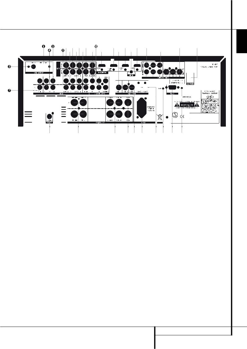
AM Antenna
FM Antenna
Tape Inputs
Tape Outputs
Subwoofer Output
DVD Audio Inputs
CD Inputs
Video 1 Audio Outputs
Aux input stereo minijack
6-Channel Direct Inputs
Digital Audio Outputs
NOTE: To assist in making the correct connections for multichannel input/output and speaker connections, all connection jacks and terminals have been color coded in conformance with the latest CEA standards as follows:
Front Left: |
White |
Front Right: |
Red |
Center: |
Green |
Surround Left: |
Blue |
Surround Right: |
Gray |
Subwoofer (LFE): |
Purple |
Digital Audio: |
Orange |
Composite Video: |
Yellow |
Component Video “Y”: |
Green |
Component Video “Pr”: |
Red |
Component Video “Pb”: |
Blue |
Video Monitor Outputs |
Video 2 Audio Inputs |
|
DVD Video Inputs |
Coaxial Digital Inputs |
|
Front Speaker Outputs |
Video 2 Video Inputs |
|
Center Speaker Outputs |
Video 1 Video Outputs |
|
Surround Speaker Outputs |
Video 1 Video Inputs |
|
Switched AC Accessory Outlet |
Optical Digital Inputs |
|
Video 1 Audio Inputs |
RS-232 |
Serial Port |
AC Power Cord |
RS-232 |
Mode |
Video 2 Component Video Inputs |
! RS-232 |
Reset |
Component Video Outputs |
" HDMI Inputs |
|
Video 1 Component Video Inputs |
# HD MI Output |
|
|
Main Power Switch |
|
AM Antenna: Connect the AM loop antenna supplied with the receiver to these terminals. If an external AM antenna is used, make connections to the AM and GND terminals in accordance with the instructions supplied with the antenna.
FM Antenna: Connect the supplied indoor or an optional external FM antenna to this terminal.
Tape Inputs: Connect these jacks to the PLAY/OUT jacks of an audio recorder.
Tape Outputs: Connect these jacks to the RECORD/INPUT jacks of an audio recorder.
Subwoofer Output: Connect this jack to the line-level input of a powered subwoofer. If an external subwoofer amplifier is used, connect this jack to the subwoofer amplifier input.
DVD Audio Inputs: Connect these jacks to the analog audio jacks on a DVD or other audio or video source.
CD Inputs: Connect these jacks to the analog output of a compact disc player or CD changer or any other audio source.
Video 1 Audio Outputs: Connect these jacks to the RECORD/INPUT audio jacks on a VCR or any other Audio recorder.
Aux input stereo minijack: Connect this minijack to any audio source, typically MP3 players or portable CD players. An analog headphone output jack or line level out jack may be used.
REAR PANEL CONNECTIONS 7
ENGLISH

Rear Panel Connections
6-Channel Direct Inputs: These jacks are used for connection to source devices such as DVD-Audio or SACD players with discrete analog outputs.
Digital Audio Output: Connect this jack to the matching digital input connector on a digital recorder such as a CD-R or MiniDisc recorder.
Video Monitor Outputs: Connect this jack to the composite and/or S-Video input of a TV monitor or video projector to view the on-screen menus and the output of any standard Video or S-Video source selected by the receiver’s video switcher.
DVD Video Inputs: Connect these jacks to the composite or S-Video output jacks on a DVD player or other video source.
Front Speaker Outputs: Connect these outputs to the matching + or – terminals on your left and right speakers. In conformance with the new CEA color code specification, the White terminal is the positive, or "+" terminal that should be connected to the red (+) terminal on Front Left speaker with the older color coding, while the Red terminal is the positive, or "+" terminal that should be connected to the red (+) terminal on Front Right speaker. Connect the black (–) terminals on the AVR to the black (–) terminals on the speakers. See page 13 for more information on speaker polarity.
Center Speaker Outputs: Connect these outputs to the matching + and – terminals on your center channel speaker. In conformance with the new CEA color code specification, the Green Terminal is the positive, or "+" terminal that should be connected to the red (+) terminal on speakers with the older color coding. Connect the black (–) terminal on the AVR to the black negative (–) terminal on your speaker. (See page 13 for more information on speaker polarity.)
Surround Speaker Outputs: Connect these outputs to the matching + and – terminals on your surround channel speakers. In conformance with the new CEA color code specification, the Blue terminal is the positive, or "+" terminal that should be connected to the red (+) terminal on the Surround Left speaker with older color coding, while the Gray terminal should be connected to the red (+) terminal on the Surround Right speaker with the older color coding. Connect the black (–) terminal on the AVR to the matching black negative (–) terminals for each surround speaker. (See page 13 for more information on speaker polarity.)
Switched AC Accessory Outlet: This outlet may be used to power any device that you wish to have turn on when the AVR is turned on with the System Power Control switch 2.
Note: The total power consumption of all devices connected to the accessory outlets should not exceed 50 W from the Switched Outlet .
Video 1 Audio Inputs: Connect these jacks to the PLAY/OUT audio jacks on a TV or other audio or video source.
AC Power Cord: Connect the AC plug to an (unswitched if possible) AC wall output.
Video 2 Component Video Inputs:
Connect the Y/Pr/Pb component video outputs of an HDTV Set-top convertor, satellite receiver, or other video source device with component video outputs to these jacks.
Monitor Component Video Outputs:
Connect these outputs to the component video inputs of a video projector or monitor. When a source connected to one of the two
Component Video Inputs is selected the signal will be sent to these jacks.
Video 1 Component Video Inputs:
Connect the Y/Pr/Pb component video outputs of a DVD player to these jacks.
Note: All component inputs/outputs can be used for RGB signals too, in the same way as described for the Y/Pr/Pb signals, then connected to the jacks with the corresponding color.
RGB connection is not possible if the source outputs a separate sync signal (see page 15).
Video 2 Audio Inputs: Connect these jacks to the PLAY/OUT audio jacks on a second VCR or other audio or video source.
Coaxial Digital Inputs: Connect the coax digital output from a DVD player, HDTV receiver, the output of a compatible computer sound card playing MP3 files or streams, LD player, MD player or CD player to these jacks. The signal may be either a Dolby Digital signal, DTS signal, a 2 channel MPEG 1 signal, or a standard PCM digital source. Do not connect the RF digital output of an LD player to these jacks.
Video 2 Video Inputs: Connect these jacks to the PLAY/OUT composite or S-Video jacks on a second VCR or other video source.
Video 1 Video Outputs: Connect these jacks to the RECORD/INPUT composite or S-Video jack on a VCR.
Video 1 Video Inputs: Connect these jacks to the PLAY/OUT composite or S-Video jacks on a TV or other video source.
Optical Digital Inputs: Connect the optical digital output from a DVD player, HDTV receiver, the output of a compatible computer sound card playing MP3 files or streams, LD player, MD player or CD player to these jacks. The signal may be either a Dolby Digital signal, a DTS signal, a 2 channel MPEG 1 signal, or a standard PCM digital source.
RS-232 Serial Port: This specialized connector may be used with your personal computer in case Harman Kardon offers a software upgrade for the receiver at some time in the future.
RS-232 Mode: Leave this switch popped out in the Operate position unless the AVR 155 is being upgraded.
! RS-232 Reset: This switch is only used during a software upgrade. A standard processor reset is performed by pressing and holding the front-panel Tone button while the receiver is in Standby.
" HDMI Inputs: Connect the HDMI output of video sources such as a DVD player, set-top box or HDTV tuner to either of these jacks.
# HDMI Output: Connect this jack to the HDMI input on a compatible HDMI-equipped video display.
Main Power Switch
Press "On" on this button to apply power to the AVR and place it in a Standby Mode, as indicated by the amber front panel LED 2. This button MUST be pressed On to operate the unit.
To turn the unit off completely and prevent the use of the remote control, this switch should be pressed "Off".
NOTE: This switch is normally left in the “ON” position.
NOTE ON VIDEO CONNECTIONS: When connecting a video source product such as a VCR, DVD player, satellite receiver, cable set-top box, personal video recorder or video game to the AVR 155, you may use either a composite or S-video connection, but not both.
8 REAR PANEL CONNECTIONS

Main Remote Control Functions |
|
|
|
ENGLISH |
0 Power Off Button |
|
|
2 1 0 |
|
|
|
|
||
1 IR Transmitter Window |
|
|
|
|
|
|
|
|
|
2 Program Indicator |
|
|
|
|
3 Power On Button |
|
|
|
|
4 Input Selectors |
|
|
|
|
5 AVR Selector |
|
|
|
|
6 AM/FM Tuner Select |
|
3 |
|
|
7 6-Channel Direct Input |
4 |
|
|
|
8 Test Button |
|
|
|
|
9 Sleep Button and Program Up Button |
|
5 |
|
|
A Surround Mode Select and Program Down |
|
6 |
|
|
B Night Mode |
|
|
|
|
C Channel Select Button |
|
|
|
|
D ⁄ /¤ Buttons |
8 |
|
|
7 |
E ‹ Button |
|
|
||
F OK Button |
|
9 |
|
|
G Digital Select |
|
|
|
|
H Numeric Keys |
|
|
|
|
A |
|
|
|
|
I Tuner Mode |
|
|
|
|
|
|
|
||
J Direct Button |
|
L |
|
|
|
|
|
||
K Tuning Up/Down |
C |
|
|
|
L On-Screen Display Button (OSD) |
|
|
|
|
M Dolby Mode Select Button |
|
D |
|
|
|
|
F |
||
N DTS Digital Mode Selector |
|
|
|
|
O Logic 7 Mode Select Button |
E |
|
|
|
P Transport Controls |
|
|
|
|
Q Tone Mode |
|
|
|
|
Skip Up/Down Buttons |
G |
|
|
|
Stereo Mode Select Button |
|
|
|
|
DTS Neo:6 Mode Select |
|
D |
|
|
Macro Buttons |
|
|
|
|
RDS Selector Button |
|
H |
|
|
Preset Up/Down |
|
|
|
|
Clear Button |
|
|
|
|
Memory Button |
I |
|
|
|
Delay/Prev. Ch. |
|
|
||
|
J |
|
|
|
› Button |
|
|
|
|
|
|
|
|
|
Speaker Select |
K |
|
|
|
Mute |
|
Q |
|
|
Volume Up/Down |
|
|
||
TV/Video Selector |
|
|
|
|
|
|
|
|
|
Dim Button |
M |
|
|
|
|
N |
|
||
|
|
|
|
|
|
B |
|
|
|
|
|
|
O |
|
|
|
|
|
|
NOTE: The function names shown here are each |
|
|
|
P |
|
|
|
|
|
button’s feature when used with the AVR. Most |
|
|
|
|
buttons have additional functions when used |
|
|
|
|
with other devices. See page 46-47 for a list of |
|
|
|
|
these functions. |
|
|
|
|
|
|
|
|
MAIN REMOTE CONTROL FUNCTIONS 9 |
Main Remote Control Functions
IMPORTANT NOTE: The AVR 155’s remote may be programmed to control up to seven devices, including the AVR. Before using the remote, it is important to remember to press the Input Selector button 45 that corresponds to the unit you wish to operate. In addition, the AVR’s remote is shipped from the factory to operate the AVR and most Harman Kardon CD or DVD players and cassette decks. The remote is also capable of operating a wide variety of other products using the control codes that are part of the remote. Before using the remote with other products, follow the instructions on pages 50-51 to program the proper codes for the products in your system.
It is also important to remember that many of the buttons on the remote take on different functions, depending on the product selected using the Input Selector Button 4. The descriptions shown here primarily detail the functions of the remote when it is used to operate the AVR. (See page 46-47 for information about alternate functions for the remote’s buttons.)
0 Power Off Button: Press this button to place the AVR or a selected device unit in the Standby mode.
1IR Transmitter Window: Point this window towards the AVR when pressing buttons on the remote to make certain that infrared commands are properly received.
2 Program Indicator: This three-color indicator is used to guide you through the process of programming the remote. (See page 43 for information on programming the remote.)
3 Power On Button: Press this button to turn on the power to a device selected by pressing one of the Input Selectors 4 (except Tape).
4 Input Selectors: Pressing one of these buttons will perform three actions at the same time. First, if the AVR is not turned on, this will power up the unit. Next, it will select the source shown on the button as the input to the AVR. Finally, it will change the remote control so that it controls the device selected.
After pressing one of these buttons you must press the AVR Selector button 5 again to operate the AVR’s functions with the remote.
5AVR Selector: Pressing this button will switch the remote so that it will operate the AVR’s functions. If the AVR is in the Standby mode, it will also turn the AVR on.
6AM/FM Tuner Select: Press this button to select the AVR’s tuner as the listening choice. Pressing this button when the tuner is in use will select between the AM and FM bands.
7 6-Channel Direct Input: Press this button to select the device connected to the
6-Channel Direct Inputs .
8Test Tone: Press this button to begin the sequence used to calibrate the AVR’s output levels. (See page 23-24 for more information on calibrating the AVR).
9Sleep Button: Press this button to place the unit in the Sleep mode. After the time shown in the display, the AVR will automatically go into the Standby mode. Each press of the button changes the time until turn-off in the following order:
Hold the button pressed for two seconds to turn off the Sleep mode setting.
Note that this button is also used to change channels on your TV, VCR and Sat receiver when the appropriate source is selected, using the device Input Selectors 4.
A Surround Mode Selector: Press this button to select any of the HALL, THEATER surround modes. Note that depending on the type of input, some modes are not always available. (See page 34-35 for more information about surround modes.) Note that this button is also used to tune channels on your TV, VCR and Sat receiver when the appropriate source is selected using the device Input Selector 4.
B Night Mode: Press this button to activate the Night mode. This mode is available only with Dolby Digital encoded sources, and it preserves dialog (center channel) intelligibilty at low volume levels (See page 36 for more information).
C Channel Select Button: This button is used to start the process of setting the AVR’s output levels with an external source. Once this button is pressed, use the ⁄/¤ buttons D to select the channel being adjusted, then press the OK button F, followed by the ⁄/¤ buttons
Dagain, to change the level setting. (See page 23-24 for more information.)
D⁄/¤ Buttons: These multipurpose buttons are used to change or scroll through items in the on-screen menus or on the front panel or to make configuration settings such as digital inputs or delay timing. When changing a setting, first press the button for the function or setting to be changed (e.g., press the Digital Select Button G to change a digital input) and then press one of these buttons to scroll through the list of options or to increase or decrease a setting. The sections in this manual describing the individual features and functions contain specific information on using these buttons for each application.
When the AVR remote is being programmed for the codes of another device, these buttons are also used in the “Auto Search” process (See page 43 for more information on programming the remote.)
10 MAIN REMOTE CONTROL FUNCTIONS
Main Remote Control Functions
E ‹ Button: This button is used to change the menu selection or setting during some of the setup procedures for the AVR.
F OK Button: This button is used to enter settings into the AVR’s memory. It is also used in the setup procedures for delay time, speaker configuration and channel output level adjustment.
G Digital Select: Press this button to assign one of the digital inputs *Ó to a source. (See page 34 for more information on using digital inputs.)
H Numeric Keys: These buttons serve as a ten-button numeric keypad to enter tuner preset positions. They are also used to select channel numbers when TV, VCR or Sat receiver has been selected on the remote, or to select track numbers on a CD, DVD or LD player, depending on how the remote has been programmed.
ITuner Mode: Press this button when the tuner is in use to select between automatic tuning and manual tuning. When the button is pressed so MANUAL appears in the Main Information Display Ò, pressing the Tuning buttons K) will move the frequency up or down in single-step increments. When the FM band is in use and AUTO appears in the Main Information Display Ò, pressing this button will change to monaural reception making even week stations audible. (See page 41 for more information.)
J Direct Button: Press this button when the tuner is in use to start the sequence for direct entry of a station’s frequency. After pressing the button simply press the proper Numeric Keys H to select a station (See page 41 for more information on the tuner).
K Tuning Up/Down: When the tuner is in use, these buttons will tune up or down through the selected frequency band. If the Tuner Mode button I has been pressed or the Band button ! on the front panel was held pressed so that AUTO appears in the Main Information Display Ò, pressing either of the buttons will cause the tuner to seek the next station with acceptable signal strength for quality reception. When the MANUAL appears in the Main Information Display Ò, pressing these buttons will tune stations in single-step increments. (See page 41 for more information.)
L OSD Button: Press this button to activate the On Screen Display (OSD) system used to set up or adjust the AVR’s parameters.
M Dolby Mode Selector: This button is used to select one of the available Dolby Surround processing modes. Each press of this button will select one of the Dolby Pro Logic II modes, Dolby 3 Stereo or Dolby Digital. Note that the Dolby Digital mode is only available with a digital input selected and the other modes only as long as a Dolby Digital source is not playing (except Pro Logic II with Dolby Digital 2.0 recordings, see page 35-36). See page 35 for the available Dolby surround mode options.
N DTS Digital Mode Selector: When a DTS source is in use the AVR will select the appropriate mode automatically and no other mode will be available. Pressing this button will display the mode currently selected by the AVR´s decoder, depending on the surround material played and the speaker setting. When a DTS source is not in use, this button has no function. (See page 36 for the available DTS options.)
O Logic 7 Selector: Press this button to select one of the available Logic 7 surround modes. (See page 36 for the available Logic 7 options.)
P Transport Control Buttons: These buttons do not have any functions for the AVR, but they may be programmed for the forward/reverse play operation of a wide variety of CD or DVD players, and audio or videocassette recorders. (See page 43 for more information on programming the remote.)
Q Tone Mode : Pressing this button enables or disables the Balance, Bass and Treble tone controls. When the button is pressed so that the words TONE IN appear in the Main Information Display Ò, the settings of the Bass and Treble controls and of the Balance control will affect the output signals, and may be adjusted with the ⁄/¤ Buttons $. When the button is pressed so that the words TONE OUT appear in the Main Information Display Ò, the output signal will be "flat", without any balance, bass or treble alteration. When pressing this button to make TONE IN or TONE OUT appear in the Display, switch between these two options with the Up/Down button n.
Skip Up/Down Buttons: These buttons do not have a direct function with the AVR, but when used with a compatibly programmed CD or DVD player/changer they will change the tracks on the disc currently being played.
Stereo Mode Selector: Press this button to select a stereo playback mode. When the button is pressed so that DSP SURROUND OFF appears in the Main Information Display Ò, the AVR will operate in a bypass mode with true fully analog, two-channel left/right stereo mode with no surround processing or bass management as opposed to other modes where digital processing is used. When the button is pressed so that 5 CH STEREO appears, the stereo signal is routed to all five speakers, if installed. (See page 20-21 for more information on stereo playback modes).
DTS Neo:6 Mode Selector: Pressing this selector button cycles the AVR through the various DTS Neo:6 modes, which extract a five-channel surround field from two-channel program material (from PCM source or analog input signal). The first press selects the last DTS Neo:6 surround mode that was in use, and each subsequent press selects the next mode.
Macro Buttons: Press these buttons to store or recall a “Macro”, which is a pre-pro- grammed sequence of commands stored in the remote. (See page 44 for more information on storing and recalling macros).
RDS Select Button: Press this button to display the various messages that are part of the RDS data system of the AVR’s tuner. (See page 42 for more information on RDS).
Preset Up/Down: When the tuner is in use, press these buttons to scroll through the stations programmed into the AVR’s memory. When CD or DVD is selected using the Input Selector button 4, these buttons may function as Slow Fwd/Rev (DVD) or ”+10” (CD, CDR).
Clear Button: Press this button to clear incorrect entries when using the remote to directly enter a radio station’s frequency.
MAIN REMOTE CONTROL FUNCTIONS 11
ENGLISH

Main Remote Control Functions
Memory Button: Press this button to enter a radio station into the AVR ’s preset memory. Two underline indicators will flash at the right side of the Main Information Display Ò, you then have five seconds to enter a preset memory location using the Numeric Keys H. (See page 41 for more information).
Delay/Prev Ch.: Press this button to begin the process for setting the delay times used by the AVR when processing surround sound. After pressing this button, the delay times are entered by pressing the OK button F and then using the ⁄/¤ buttons D to change the setting. Press the OK button again to complete the process. (See page 26 for more information).
› Button: Press this button to change a setting or selection when configuring many of the AVR’s settings.
Speaker Select: Press this button to begin the process of configuring the AVR’s Bass Management System for use with the type of speakers used in your system. Once the button has been pressed, use the ⁄/¤ buttons D to select the channel you wish to set up.
Press the OK Button F and then select the speaker type (Large, Small or None) appropriate with the speaker in use. (See page 24 for more information).
Mute: Press this button to momentarily silence the AVR or TV set being controlled, depending on which device has been selected. When the AVR remote is being programmed to operate another device, this button is pressed with the Input Selector button 4 to begin the programming process. (See page 43 for more information on programming the remote).
Volume Up/Down: Press these buttons to raise or lower the system volume.
TV/Video Button: This button does not have a direct function on the AVR, but when used with a compatibly programmed VCR, DVD or satellite receiver that has a “TV/Video” function, pressing this button will switch between the output of the player or receiver and the external video input to that player. Consult the Owner’s Manual for your specific player or receiver for the details of how it implements this function.
NOTE: With the press of any remote button the
Input Selector button 45 associated with the button pressed will briefly flash red to confirm the transmission of the command, as long as there is a function for that button with the device selected (see function list on
pages 46-47).
Dim Button: Press this button to activate the Dimmer function, which reduces the brightness of the front-panel display, or turns it off entirely. The first press of the button shows the default state. Press the button again to change the display to reduce the brightness by 50%, and press it again within five seconds and the main display will go completely dark. Note that this setting is temporary; regardless of any changes, the display will always return to full brightness when the AVR is turned on. The white illumination inside the Volume Control Button is lit only when the front-panel display is on full brightness. If you press a button while the display is dark, it will light up for some seconds to inform you that your signal has been received. Also the Volume Control light will light up, then go dark again some seconds later.
12 MAIN REMOTE CONTROL FUNCTIONS
Installation and Connections
After unpacking the unit, and placing it on a solid surface capable of supporting its weight, you will need to make the connections to your audio and video equipment.
Audio Equipment Connections
We recommend that you use high-quality interconnect cables when making connections to source equipment and recorders to preserve the integrity of the signals.
When making connections to audio source equipment or speakers it is always a good practice to unplug the unit from the AC wall outlet. This prevents any possibility of accidentally sending audio or transient signals to the speakers that may damage them.
1. Connect the analog output of a CD player to the CD inputs .
NOTE: When the CD player has both fixed and variable audio outputs it is best to use the fixed output unless you find that the input to the receiver is so low that the sound is noisy, or so high that the signal is distorted.
2.Connect the analog Play/Out jacks of a cassette deck, MD, CD-R or other audio recorder to the Tape Input jacks . Connect the analog Record/In jacks on the recorder to the Tape Output jacks on the AVR.
3.Connect the digital output of any digital sources such as a CD or DVD changer or player, advanced video game, a digital satellite receiver, HDTV tuner or digital cable set-top box or the output of a compatible computer sound card to the Optical and Coaxial Digital Inputs
*Ó.
We recommend connecting the coaxial digital audio output of your DVD player to the Coax 1 Digital Audio Input , since that digital input is assigned to the DVD source by default.
The Video 2/Cable/Sat source defaults to the
Optical 1 Digital Audio Input . If your cable television set-top box or satellite receiver is equipped with an optical digital audio output, we recommend that you connect it to this input to obtain the benefits of higher-quality digital audio (such as PCM, Dolby Digital 2.0 or Dolby Digital 5.1 signals when broadcast by your cable or satellite provider).
4.Connect the Coaxial or Optical Digital Outputs on the rear panel of the AVR to the matching digital input connections on a CD-R or MiniDisc recorder.
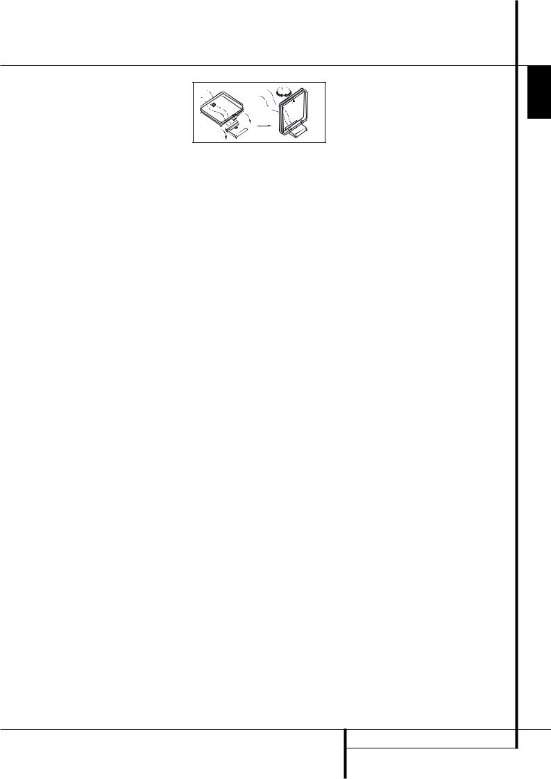
5.Assemble the AM Loop Antenna supplied with the unit as shown below. Connect it to the AM and GND screw terminals .
6.Connect the supplied FM antenna to the FM (75 ohm) connection . The FM antenna may be an external roof antenna, an inside powered or wire lead antenna or a connection from a cable system. Note that if the antenna or connection uses 300-ohm twin-lead cable, you should use a 300-ohm-to-75-ohm adapter to make the connection.
7.Connect an MP3 player, iPod or portable CD to the Aux In minijack audio input to listen to music through the AVR 155. Usually the headphone jack on the portable player is the only one that can be used, and you have to adjust the volume to be at a reasonable level on the portable unit as well as on the AVR 155. If a fixed Line Out jack or dual phono plug output jacks are available, using these with the proper cables may result in better sound quality.
8.Connect the front, center and surround speaker outputs to the respective speakers.
To assure that all the audio signals are carried to your speakers without loss of clarity or resolution, we suggest that you use high-quality speaker cable. Many brands of cable are available and the choice of cable may be influenced by the distance between your speakers and the receiver, the type of speakers you use, personal preferences and other factors. Your dealer or installer is a valuable resource to consult in selecting the proper cable.
Regardless of the brand of cable selected, we recommend that you use a cable constructed of fine, multistrand copper with an area greater than 2 mm2.
Cable with an area of 1.5 mm2 may be used for short runs of less than 4 m. We do not recommend that you use cables with an area less than 1mm2 due to the power loss and degradation in performance that will occur.
Cables that are run inside walls should have the appropriate markings to indicate listing with any appropriate testing agency standards. Questions about running cables inside walls should be referred to your installer or a licensed electrician who is familiar with the applicable local building codes in your area.
When connecting wires to the speakers, be certain to observe proper polarity. Note that the positive (+) terminal of each speaker connection now carries a specific color code as noted on page 8. However, most speakers will still use a red terminal for the postive (+) connection. Connect the “negative” or “black” wire to the same terminal on both the receiver and the speaker.
NOTE: While most speaker manufacturers adhere to an industry convention of using black terminals for negative and red ones for positive, some manufacturers may vary from this configuration. To assure proper phase and optimal performance, consult the identification plate on your speaker or the speaker’s manual to verify polarity. If you do not know the polarity of your speaker, ask your dealer for advice before proceeding, or consult the speaker’s manufacturer.
We also recommend that the length of cable used to connect speaker pairs be identical. For example, use the same length piece of cable to connect the front-left and front-right or surround-left and surround-right speakers, even if the speakers are a different distance from the AVR.
9.Connections to a subwoofer are normally made via a line level audio connection from the Subwoofer Output to the line-level input of a subwoofer with a built-in amplifier. When a passive subwoofer is used, the connection first goes to a power amplifier, which will be connected to one or more subwoofer speakers. If you are using a powered subwoofer that does not have line-level input connections, follow the instructions furnished with the speaker for connection information.
10.If an external multi-channel audio source with 5.1 outputs such as an external digital processor/decoder, DVD-Audio or SACD player is used, connect the outputs of that device to the
6-Channel Direct Inputs .
Video Equipment Connections
Video equipment is connected in the same manner as audio components. Again, the use of highquality interconnect cables is recommended to preserve signal quality. To ensure best video performance S-Video sources should be connected to the AVR only with their S-Video In/Outputs, not with their composite video connectors too.
1.Connect a VCR’s audio and video Play/Out jacks to the Video 2 In jacks on the rear panel. The Audio and Video Record/In jacks on the VCR should be connected to the Video 1 Out jacks on the AVR.
2.Although any video device may be connected to these jacks, we recommend connecting your TV to the Audio 1 Audio/Video Input Jacks
so that you may take advantage of the fact that the remote control is preprogrammed with TV product codes for the Video 1 device.
For the same reason, we recommend connecting your video recorder, cable TV converter or satellite receiver to the Video 2 Audio/Video Input Jacks .
3.Connect the analog audio and video
outputs of a DVD or laser disc player to the DVD jacks .
INSTALLATION AND CONNECTIONS 13
ENGLISH

Installation and Connections
4. Connect the digital audio outputs of a CD, MD or DVD player, satellite receiver, cable box or HDTV converter to the appropriate Optical or
Coaxial Digital Inputs *Ó. Remember that the DVD source defaults to the
Coaxial 1 Digital Input . All other sources default to their analog inputs, although any source may be assigned to any digital audio input on the receiver.
NOTE: When connecting a device such as a digital cable box or other set-top tuner product with a digital audio output, we recommend that you connect both the digital and analog outputs of the product to your AVR. The audio input polling feature of the AVR will then be able to make certain that you have a constant audio feed, since it will automatically switch the audio input to the analog jacks if the digital feed is interrupted or not available for a particular channel.
5.Connect the Composite and S-Video (if S-Video device is in use) Monitor Output jacks on the receiver to the composite and S-Video input of your television monitor or video projector.
6.If your DVD player and monitor both have component video connections, connect the component outputs of the DVD player to the Video
1Component Video Inputs . Note that even when component video connections are used the audio connections must still be made to either the analog DVD Audio Inputs or any of the Coaxial or Optical Digital Input jacks .
7.If another component video device is available, connect it to the Video 2 Component Video Input jacks . The audio connections for this device should be made to either the
Video 2 Input jacks or any of the Coaxial or Optical Digital Input jacks .
8.If the component video inputs are used, connect the Component Video Output to the component video inputs of your TV, projector or display device.
9.If you have a camcorder, video game or other audio/video device that is connected to the AVR on a temporary, rather than permanent basis, connect the audio, video and digital audio outputs of that device to the Front Panel Inputs *ÓÔ. A device connected to the Video 3 jacks Ô is selected as the Video 3 input, and connected to the digital jacks *Ó it is selected as "Optical 3" or "Coaxial 3" input. (See page 18 for more information on input configuration.)
10.Connect the AVR to your video display using one of the following connections, even if you will also use an HDMI connection:
•If your video display has component video inputs (Y/Pr/Pb), connect the Component Video Outputs .
•If your display does not have digital or component video inputs, connect the Video Monitor Output on the AVR to the matching input on your display. Only one connection is needed, and S-video is the higher quality signal.
HDMI Connections
HDMI™ is the abbreviation for High-Definition Multimedia Interface, which is quickly becoming the standard connection point between advanced video/audio source products and displays, particularly for high-definition video signals. HDMI is a digital connection, eliminating the need to convert signals back and forth from digital to analog.
Some source or display components in your system may use DVI (Digital Video Interface) for digital video connections. DVI carries the same digital video signals as HDMI but uses a larger connector and does not transport audio or control signals. In most cases, you may mix and match DVI and HDMI digital video connections by using optional connector adapters. Note, however, that some DVI-equipped video displays are not compatible with the HDCP copy protection coding that is increasingly carried with signals connected via HDMI. If you have an HDMI source and a DVI-equipped display, you may occasionally be unable to view a program if the display does not include HDCP. This is not the fault of the AVR or your source; it simply indicates that the video display is not compatible.
The AVR 155 is equipped for HDMI switching, which means that it is able to select either of the three HDMI inputs as the source that feeds your system’s video display. This preserves the digital signal in its original form by passing it directly through from source to display. However, this also means that the AVR does not have access to the signal and thus it is not able to add menus or on-screen messages to HDMI signals, or to process the audio that may be part of the signal in an HDMI connection.
Therefore, the following connections are required when the AVR 155 is used with HDMI sources:
•Connect the HDMI output of a source to either of the HDMI Inputs ".
•Connect the HDMI Output # of the AVR to an HDMI input on your display.
•Connect either an optical or coaxial digital audio output from the source to the AVR. The default connections are Coaxial 2 for a source connected to HDMI 1 " and Optical 2 for a source connected to
HDMI 2 ". You may use any digital or analog
audio source in conjunction with the HDMI inputs, but if it varies from the default you must make a change to the input’s setting, as shown on page 18.
•Even when HDMI inputs are used, it is important to make sure that a component, S-video or composite video connection is made between the AVR and your display. This is needed to view both the setup menus and onscreen messages, and to view other (nonHDMI) video sources. The AVR 155 does not convert analog video signals to HDMI.
•All component inputs/outputs can be used for RGB signals too, in the same way as described for the Y/Pr/Pb signals, then connected to the jacks with the corresponding color.
But this is only correct as long as only the three RGB video signals are output by the video source, with a sync signal in the "G" signal only, without any sync signal output separately by the source.
SCART A/V Connections
For the connections described above your video device needs RCA (cinch) connectors or/and S- Video connectors for all Audio and Video signals: Any normal video device (Not SVHS or High 8) for only playback needs 3 RCA jacks, VCRs for record and playback even 6 RCA jacks. Any S-Video device (SVHS, High 8) needs 2 RCA (Audio) and 1 S-Video jack (Video), if it´s a playback unit, or 4 RCA (Audio In/Out) and 2 S-Video (Video In/Out) jacks, if it´s a recording VCR.
Many european video devices are equipped with RCA (Cinch) or S-Video jacks only partially, not for all audio and video in/outputs needed as described above, but with a so called Scart or Euro-AV connector (almost rectangular jack with 21 pins, see drawings on next page).
In that case the following Scart to Cinch adapters or cables are needed:
•Units for playback, such as satellite receivers, camcorders, DVD or LD players, need an adapter from Scart to 3 RCA plugs, see fig. 1 (normal video devices) or from Scart to 2 RCA+1 S-Video plugs, see fig. 4 (S-Video devices).
•HiFi VCRs need an adapter from Scart to 6 RCA plugs, see fig. 2 (normal video), or from Scart to 4 Audio+2S-Video jacks, see fig. 5
(S-Video VCR). Read carefully the instruction attached to the adapter to find which of the six plugs is used for the record signal to the VCR (connect with the AVR´s Out jacks) and for the playback signal from the VCR (connect with the AVR´s In jacks). Do not misconnect Audio and Video signals. Don´t hesitate to consult your dealer, if you are uncertain.
14 INSTALLATION AND CONNECTIONS
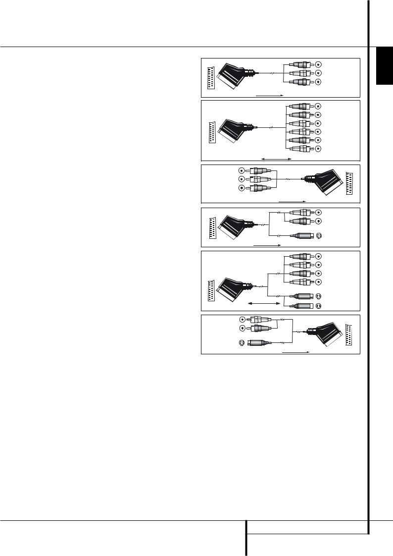
Installation and Connections |
|
|
|
|
• If you use only normal video devices the TV |
|
|
Black |
|
monitor needs an adapter from 3 RCA plugs to |
|
|
||
Figure 1: |
|
Yellow |
||
Scart (fig. 3) only. If also S-Video devices are |
|
|||
SCART/Cinch-Adapter |
|
|||
|
|
|||
used an adapter from 2 RCA+1S-Video plugs |
|
Red |
||
for playback; |
|
|||
to Scart is needed additionally (fig. 6), |
signal flow: |
|
|
|
connected to the SCART input on your TV that |
SCART ’ Cinch |
|
|
|
is provided for S-Video. |
|
|
Black |
|
|
|
|
||
Note that only the video plugs (the "yellow" |
|
|
Red |
|
cinch plug in fig. 3 and the S-Video plug in |
|
|
Blue1 |
|
fig. 6) must be connected to the TV Monitor |
|
|
Yellow |
|
Output , and the volume on the TV must be |
Figure 2: |
|
||
|
Green1 |
|||
reduced to minimum. |
SCART/Cinch-Adapter |
|
||
Important Note for Adapter Cables: |
for record and playback; |
|
White |
|
signal flow: |
|
|
||
If the cinch connectors of the adapter you’ll use |
SCART Cinch |
|
|
|
are labeled, connect the Audio and Video ”In” |
|
Black |
|
|
plugs with the corresponding Audio and Video |
Figure 3: |
Yellow |
|
|
”In” jacks on the AVR (and with a VCR connect |
|
|||
Cinch/SCART-Adapter for |
Red |
|
||
the ”Out” plugs to the ”Out” jacks on the VCR). |
playback; |
|
||
|
|
|||
Note that with some adapter types it may be just |
signal flow: |
|
|
|
turned around: If no signal is audible/visible when |
Cinch ’ SCART |
|
|
|
|
|
|
||
the VCR is playing connect the “Out” plugs to the |
|
|
Red |
|
”In” jacks on the AVR and turned around. If the |
Figure 4: |
|
Black |
|
adapter plugs are not labeled in that way, pay |
SCART/S-Video Adapter |
|
|
|
attention to the signal flow directions as shown |
for playback; |
|
S-Video In |
|
in the diagrams above and in the instruction |
signal flow: |
|
|
|
attached to the adapter. If uncertain, don’t hesi- |
SCART ’ Cinch |
|
|
|
|
|
|
||
tate to consult your dealer. |
|
|
Black |
|
Important Notes for S-Video connections: |
|
|
Red |
|
Only the S-Video In/Out of S-Video devices must |
|
|
Blue1 |
|
be connected to the AVR, NOT both, normal video |
Figure 5: |
|
Yellow |
|
and S-Video In/Outputs (except the TV, see item |
|
|
||
SCART/S-Video Adapter |
|
|
||
below). |
for record and playback; |
|
S-Video In |
|
When both connections are made, only the |
signal flow: |
|
S-Video Out |
|
S-Video signal will be viewed on the screen. |
SCART Cinch |
|
||
|
|
|||
Important Note for the Use of |
Figure 6: |
Red |
|
|
SCART-Cinch Adapters: |
Black |
|
||
When video sources are connected to the TV |
SCART/S-Video Adapter |
|
|
|
for playback; |
|
|
||
directly with a SCART cable, specific control |
S-Video Out |
|
||
signal flow: |
|
|||
signals apart from Audio/Video signals will be fed |
|
|
||
Cinch ’ SCART |
|
|
||
to the TV. These specific signals are: With all video |
1 Also other colours possible, e.g. brown and grey. |
|||
|
||||
sources, the signal for automatic input selection |
|
|
|
|
that switches the TV automatically to the appro- |
|
|
|
|
priate input as soon as the video source is start- |
|
|
|
|
ed. And with DVD players, the signals automati- |
AVR only when no separate sync signal is needed |
NOTE: Many audio and video products go into a |
||
cally turning the TV to 4:3/16:9 format (with 16:9 |
(see last ”Video Connection Note” on page 14). |
Standby mode when they are used with switched |
||
TVs or with 4:3 TVs with selectable 16:9 format) |
|
|
outlets, and cannot be fully turned on using the |
|
and turning the RGB video decoder of the TV on |
Power Connections |
|
outlet alone without a remote control command. |
|
or off, depending on the DVD player´s setting. |
|
Once the power cord is connected, you are |
||
With any adapter cable, these control signals will |
AC Power Connections |
|
||
|
almost ready to enjoy the AVR 155’s incredible |
|||
be lost and the appropriate setting of the TV must |
|
|||
This unit is equipped with one accessory AC out- |
||||
power and fidelity! |
||||
be made manually. |
||||
let. It may be used to power Accessory devices, |
||||
|
||||
|
|
|||
Note for RGB signal with SCART: |
but it should not be used with high-current draw |
|
||
equipment such as power amplifiers. The total |
|
|||
If you use a unit providing RGB signals on a |
|
|||
power draw to the Switched Outlet must |
|
|||
SCART output (as e.g. most DVD players do) and |
|
|||
not exceed 50 watts. |
|
|
||
you want to use that RGB signal, this SCART out- |
|
|
||
|
|
|
||
put must be connected directly to your TV. |
The Switched outlet will receive power only |
|
||
Although the AVR can switch three-way video |
when the unit is on completely. This is recom- |
|
||
signals (like component signals Y/Pb/Pr), most TVs |
mended for devices that have no power switch |
|
||
need separate sync signals for RGB (also with |
or a mechanical power switch that may be left in |
|
||
SCART) that cannot be switched and provided by |
the “ON” position. |
|
|
|
the AVR. RGB signals can be pathed through the |
|
|
|
|
INSTALLATION AND CONNECTIONS 15
ENGLISH
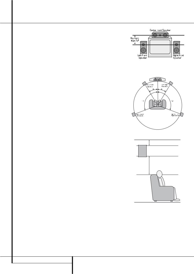
Installation and Connections
Speaker Selection
No matter which type or brand of speakers is used, the same model or brand of speaker should be used for the front-left, center and front-right speakers. This creates a seamless front soundstage and eliminates the possibility of distracting sonic disturbances that occur when a sound moves across mismatched front-channel speakers.
Speaker Placement
The placement of speakers in a multichannel home-theater system can have a noticeable impact on the quality of sound reproduced.
Depending on the type of center-channel speaker in use and your viewing device, place the center speaker either directly above or below your TV, or in the center behind a perforated front-projection screen.
Once the center-channel speaker is installed, position the left-front and right-front speakers so that they are as far away from one another as the center-channel speaker is from the preferred listening position. Ideally, the front-channel speakers should be placed so that their tweeters are no more than 60cm above or below the tweeter in the center-channel speaker.
They should also be at least 0.5 meter from your TV set unless the speakers are magnetically shielded to avoid colourings on the TV screen. Note that most speakers are not shielded, even with complete surround sets only the Center speaker may be.
Depending on the specifics of your room acoustics and the type of speakers in use, you may find that imaging is improved by moving the front-left and front-right speakers slightly forward of the center-channel speaker. If possible, adjust all front loudspeakers so that they are aimed at ear height when you are seated in the listening position.
Using these guidelines, you’ll find that it takes some experimentation to find the correct location for the front speakers in your particular installation. Don’t be afraid to move things around until the system sounds correct. Optimize your speakers so that audio transitions across the front of the room sound smooth.
When the AVR is used in 5.1-channel operation, the preferred location for surround speakers is on the side walls of the room, at or slightly behind the listening position.
Subwoofers produce largely nondirectional sound, so they may be placed almost anywhere in a room. Actual placement should be based on room size and shape and the type of subwoofer used. One method of finding the optimal location for a subwoofer is to begin by placing it in the front of the room, about 15 cm from a wall, or near the front corner of the room. Another method is to temporarily place the subwoofer in the spot where you will normally sit, and then walk around the room until you find a spot where the subwoofer sounds best. Place the subwoofer in that spot. You should also follow the instructions of the subwoofer’s manufacturer, or you may wish to experiment with the best location for a subwoofer in your listening room.
A) Front Channel Speaker Installation with Direct-View TV Sets or Rear-Screen Projectors
5.1-Channel System
At least 15 cm from celling 
At least 60 cm
16 INSTALLATION AND CONNECTIONS
 Loading...