


|
Table of Contents |
|
1. |
Safety Precautions And Warnings........................ |
3 |
2. |
General Information............................................... |
4 |
3. |
Using the Scan Tool.............................................. |
13 |
4. |
Review Data........................................................... |
31 |
5. |
OBD II Diagnostics................................................ |
33 |
6. |
Ready Test............................................................. |
63 |
7. |
Print Data............................................................... |
68 |
8. |
Limited 90 Day Warranty...................................... |
70 |
This device complies with Part 15 of the FCC Rules. Operation is subject to the following two conditions: (1) this device may not cause harmful interference, and (2) this device must accept any interference received, including interference that may cause undesired operation.
Page 2 |
For technical questions, please call 1-888-866-5797. Item 60693 |

1. Safety Precautions And Warnings
To prevent personal injury or damage to vehicles and/ or the Scan Tool, read this instruction manual first and observe the following safety precautions, at
a minimum, whenever working on a vehicle:
1.Always perform automotive testing in a safe environment.
2.Wear safety eye protection that meets ANSI standards.
3.Keep clothing, hair, hands, tools, test equipment, etc. away from all moving or hot engine parts.
4.Operate the vehicle in a well ventilated work area: Exhaust gases are poisonous.
5.Put blocks in front of the drive wheels and never leave the vehicle unattended while running tests.
6.Use extreme caution when working around the ignition coil, distributor cap, ignition wires and spark plugs. These components create hazardous voltages when the engine is running.
7.Put the transmission in PARK (for automatic transmission) or NEUTRAL (for manual transmission) and make sure the parking brake is engaged.
8.Keep a fire extinguisher suitable for gasoline/ chemical/electrical fires nearby.
9.Don't connect or disconnect any test equipment while the ignition is on or the engine is running.
10.Keep the Scan Tool dry, clean, free from oil, water or grease. Use a mild detergent on a clean cloth to clean the outside of the Scan Tool, when necessary.
11.WARNING: This product contains or, when used, produces a chemical known to the State of California to cause cancer and birth defects or other reproductive harm. (California Health & Safety Code § 25249.5, et seq.)
Item 60693 For technical questions, please call 1-888-866-5797. |
Page 3 |

2. General Information
2.1 On-Board Diagnostics (OBD) II
The first generation of On-Board Diagnostics (called OBDI) was developed by the California Air Resources Board (ARB) and implemented in 1988 to monitor some of the emission control components on vehicles. As technology evolved and the desire to improve the On-Board Diagnostic system increased, a new generation of On-Board Diagnostic system was developed. This second generation of OnBoard Diagnostic regulations is called "OBD II".
The OBD II system is designed to monitor emission control systems and key engine components by performing either continuous or periodic tests of specific components and vehicle conditions. When a problem is detected, the OBD II system turns on a warning lamp (MIL) on the vehicle instrument panel to alert the driver typically
by the phrase of “Check Engine” or “Service Engine Soon”.
The system will also store important information about the detected malfunction so that a technician can accurately find and fix the problem. Here are three examples:
1.Whether the Malfunction Indicator Light (MIL) is commanded 'on' or 'off';
2.Which, if any, Diagnostic Trouble Codes (DTCs) are stored;
3.Readiness Monitor status.
Page 4 |
For technical questions, please call 1-888-866-5797. Item 60693 |
2.2 Diagnostic Trouble Codes (DTCs)
OBD II Diagnostic Trouble Codes are codes that are stored by the on-board computer diagnostic system in response to a problem found in the vehicle. These codes identify a particular problem area and are intended to provide you with a guide
as to where a fault might be occurring within a vehicle.
These codes provide information as to where the DTC originated and the operating conditions that caused it to set. See chart below:
DTC Example
P 0 2 0 2
|
Systems |
|
|
|
|
|
|
|
B=Body |
|
|
|
|
Identifying specific |
|
|
|
|
|||||
|
C=Chassis |
|
|
|
|
malfunctioning |
|
|
P=Powertrain |
|
|
|
|
section of the |
|
|
U=Network |
|
|
|
|
systems |
|
|
|
|
|
|
|
|
|
|
|
|
|||||
Code Type |
|
Sub-systems |
|||||
Generic (SAE): |
|
1= Fuel and Air Metering |
|||||
P0, P2, P34-P39 |
|
2= Fuel and Air Metering |
|||||
B0, B3 |
|
3= Ignition System or Engine Misfire |
|||||
C0, C3 |
|
4= Auxiliary Emission Controls |
|||||
U0, U3. |
|
5= Vehicle Speed Control and Idle |
|||||
Manufacturer Specific: |
|
Controls |
|||||
P1, P30-p33 |
|
6= Computer Output Circuits |
|||||
B1, B2 |
|
7= Transmission Controls |
|||||
C1, C2 |
|
8= Transmission Controls |
|||||
U1, U2 |
|
|
|
|
|
||
|
|
|
|
|
|
|
|
Item 60693 For technical questions, please call 1-888-866-5797. |
Page 5 |
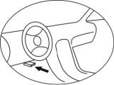
2.3 Location of the Data Link Connector (DLC)
The DLC (Data Link Connector or Diagnostic Link Connector) is the standardized 16-cavity connector where diagnostic Scan Tools interface with the vehicle's on-board computer. The DLC is usually located 12 inches from the center of the instrument
panel (dash), under or around the driver's side for most vehicles. If Data Link Connector is not located under dashboard, a
label should be there telling location. For some Asian and European vehicles, the DLC is located behind the ashtray and the ashtray must be removed to access the connector.
2.4 OBD II Readiness Monitors
An important part of a vehicle's OBD II system are the Readiness Monitors, which are indicators used to find out if all of the emissions components have been evaluated by the OBD II system. They
are running periodic tests on specific systems and components to ensure that they are performing within allowable limits.
Currently, there are eleven OBD II Readiness Monitors (or I/M Monitors) defined by the U.S. Environmental Protection Agency (EPA). Not all monitors are supported by all vehicles and the exact number of monitors in any vehicle depends on the motor vehicle manufacturer's emissions control strategy.
Page 6 |
For technical questions, please call 1-888-866-5797. Item 60693 |
Continuous Monitors
Some of the vehicle components or systems are continuously tested by the vehicle's OBD II system, while others are tested only under specific vehicle operating conditions. The continuously monitored components listed below are always ready:
1.Misfire
2.Fuel System
3.Comprehensive Components (CCM)
Once the vehicle is running, the OBD II system is continuously checking the above components, monitoring key engine sensors, watching for engine misfire, and monitoring fuel demands.
Non-Continuous Monitors
Unlike the continuous monitors, many emissions and engine system components require the vehicle to be operated under specific conditions before the monitor is ready. These monitors are termed non-continuous monitors. For different ignition type engines, the available monitors are different too.
The Following Monitors Are To Be Used For
Spark Ignition (Gasoline) Engines Only:
1.EGR System
2.O2 Sensors
3.Catalyst
4.Evaporative System
5.O2 Sensor Heater
6.Secondary Air
7.Heated Catalyst
Item 60693 For technical questions, please call 1-888-866-5797. |
Page 7 |
The Following Monitors Are To Be Used For
Compression Ignition (Diesel) Engines Only:
8.EGR System
9.NMHC Catalyst
10.NOx Aftertreatment
11.Boost Pressure System
12.Exhaust Gas Sensor
13.PM Filter
2.5 OBD II Monitor Readiness Status
OBD II systems must indicate whether or not the vehicle's PCM monitor system has completed testing on each component. Components that have been tested will be reported as “Ready”, or “Complete”, meaning they have been tested by the OBD II system.
The purpose of recording readiness status is to allow inspectors to determine if the vehicle's OBD II system has tested all the components and/or systems.
The power-train control module (PCM) sets a monitor to “Ready” or “Complete” after an appropriate drive cycle has been performed. The drive cycle that enables a monitor and sets readiness codes to “Ready” varies for each individual monitor. Once a monitor is set as “Ready” or “Complete”, it will remain in this state. A number of factors, including erasing of Diagnostic
Trouble Codes (DTCs) with a Scan Tool or a disconnected battery, can result in Readiness Monitors being set to “Not Ready”.
Since the three continuous monitors are constantly evaluating, they will be reported as “Ready” all of the time. If testing of a particular supported non-continuous monitor has not been completed, the monitor status will be reported as “Not Complete” or “Not Ready.”
Page 8 |
For technical questions, please call 1-888-866-5797. Item 60693 |
In order for the OBD monitor system to become ready, the vehicle should be driven under a variety of normal operating conditions. These operating conditions may include a mix of highway driving and stop and go, city type driving, and at least one overnight-off period. For specific information on getting your vehicle's OBD monitor system ready, please consult your vehicle Owner's Manual.
2.6 OBD II Definitions
Power-train Control Module (PCM) -- OBD II terminology for the on-board computer that controls engine and drive train.
Malfunction Indicator Light (MIL) -- Malfunction Indicator Light (Service Engine Soon, Check Engine) is a term used for the light on the instrument panel. It is to alert the driver and/or the repair technician that there is a problem with one or more of vehicle's systems and may cause emissions to exceed federal standards. If the MIL illuminates with a steady light, it indicates that a problem has been detected and the vehicle should be serviced as soon as possible. Under certain conditions, the dashboard light will blink or flash. This indicates a severe problem and flashing is intended to discourage vehicle operation. The vehicle onboard diagnostic system can not turn the MIL off until necessary
repairs are completed or the condition no longer exists.
DTC -- Diagnostic Trouble Code that identifies which section of the emission control system has malfunctioned.
Enabling Criteria -- Also termed Enabling Conditions. These are the vehicle-specific events or conditions that must occur within the engine before the various monitors will set or run. Some monitors require the vehicle to follow a prescribed “drive cycle” routine as part of the enabling criteria. Drive cycles vary among vehicles and for each monitor in any particular vehicle.
Item 60693 For technical questions, please call 1-888-866-5797. |
Page 9 |
OBD II Drive Cycle -- A specific mode of vehicle operation that provides conditions required to set all the Readiness Monitors applicable to the vehicle to the “Ready” condition. The purpose of completing an OBD II drive cycle is to force the vehicle to run its onboard diagnostics. Some form of a drive cycle needs to be performed after DTCs have been erased from the PCM's memory or after the battery has been disconnected. Running through a vehicle's complete drive cycle will “set” the Readiness Monitors so that future faults can be detected. Drive cycles vary depending on the vehicle and the monitor that needs to be reset. For vehicle specific drive cycle, consult the vehicle's Owner's Manual.
Freeze Frame Data -- When an emissions related fault occurs, the OBD II system not only sets a code but also records a snapshot of the vehicle operating parameters to help in identifying the problem. This set of values is referred to as Freeze Frame Data and may include important engine parameters such as engine RPM, vehicle speed, air flow, engine load, fuel pressure, fuel trim value, engine coolant temperature, ignition timing advance, or closed loop status.
2.7 OBD II Modes of Operation
Here is a basic introduction to the OBD II communication protocol.
Mode Byte: The first byte in the stream is the mode number. There are 10 modes for diagnostic requests. The first
byte in the response data bytes is this same number plus 64. For example, a mode 1 request would have the first data byte = 1, and the response would have the first data byte = 65. Here is a brief description of the modes:
Mode $01 – Identifies the Powertrain information and shows current data available to the Scan Tool. This data includes: DTC set, status of on-board tests, and vehicle data such as engine RPM, temperatures, ignition advance, speed, air flow rates, and closed loop status for fuel system.
Page 10 |
For technical questions, please call 1-888-866-5797. Item 60693 |
Mode $02 – Displays Freeze Frame Data. Same data as in mode 1, but it was captured and stored when a malfunction occurred and a DTC was set. Some of the PIDs for Mode $01 are not implemented in this mode.
Mode $03 – Displays the type of powertrain or emission related DTCs stored by a 5 digit code identifying the faults.
There may be more than one response message if there are more trouble codes than will fit in the data bytes of the response
message, or if there are more than one ECU computer responding.
Mode $04 – Used to clear DTCs and Freeze Frame Data. This clears all DTCs that may be set including freeze frame data and Readiness Monitors.
Mode $05 – Oxygen Sensor Test Results. This mode displays the oxygen sensor monitor screen and the test results gathered about the oxygen sensor.
There are ten numbers available for diagnostics:
1.$01 Rich-to-Lean O2 sensor threshold voltage.
2.$02 Lean-to-Rich O2 sensor threshold voltage.
3.$03 Low sensor voltage threshold for switch time measurement.
4.$04 High sensor voltage threshold for switch time measurement.
5.$05 Rich-to-Lean switch time in ms.
6.$06 Lean-to-Rich switch time in ms.
7.$07 Minimum voltage for test.
8.$08 Maximum voltage for test.
9.$09 Time between voltage transitions in ms
10.$10 Sensor Periods
Item 60693 For technical questions, please call 1-888-866-5797. |
Page 11 |

Mode $06 – Non-Continuously Monitored Systems test results. There are typically a minimum value, a maximum value, and a current value for each non-continuous monitor. This data is optional, and it is defined by a given vehicle maker if it's used.
Mode $07 – Request for DTCs (pending) from Continuously
Monitored Systems after a single driving cycle has been performed to determine if repair has fixed a problem. This is used by service technicians to verify repair was performed properly and after clearing DTCs.
Mode $08 – This special Control Mode requests control of the on-board system, test, or component bi-directionally (where applicable). This mode is manufacturer specific.
Mode $09 – Reports vehicle information. This information includes vehicle VIN number and calibration information stored in the vehicle's ECU.
Mode $0A – Request Emission-Related Diagnostic Trouble Codes with Permanent Status. This mode is required for all emissions-related DTCs. The presence of permanent DTCs at an inspection without the MIL illuminated is an indication that a proper repair was not verified by the on-board monitoring system.
Page 12 |
For technical questions, please call 1-888-866-5797. Item 60693 |

3. Using the Scan Tool
3.1 Tool Description
1
14
2 |
|
|
5 |
|
|
4 |
|
|
3 |
6 |
|
7 |
||
10 |
||
8 |
11 |
|
9 |
12 |
|
|
13 |
1.OBD II Connector – Connects the Scan Tool to the vehicle's Data Link Connector (DLC).
2.LCD Display – Displays menus and test results.
3.GREEN LED – Indicates that engine systems are running normally (The number of monitors on the vehicle which are active and performing their diagnostic testing is in the allowed limit, and no DTCs are present).
Item 60693 For technical questions, please call 1-888-866-5797. |
Page 13 |

4. YELLOW LED – Indicates there is a possible problem. A “Pending” DTC is present and/or some of the vehicle's emission monitors have not run their diagnostic testing.
5. RED LED – Indicates there is a problem in one or more of the vehicle's systems. The RED LED is also used to show that DTCs are present. DTCs are shown on the Scan Tool's display. In this case, the MIL on the vehicle's instrument panel will light steady on.
6.One-Click I/M Readiness Key – Quick-checks State Emissions readiness and drive cycle verification.
7. ESC Button – Cancels a selection (or action) from a menu or returns to the previous screen.
8.Left Scroll Button – When looking up DTC definitions, moves to previous character and views additional information on previous screens if DTC definition covers more than
one screen. Deselects all marked PID data when viewing or recording customized live data list; views previous frames of recorded data when playing back live data.
It is also used to update DTC library when pressed.
9.Help Button – Provides help information
and Code Breaker function.
10.Up Scroll Button – Moves up through menu and submenu items in menu mode. When more than one screen of data is retrieved, moves up through the current screen to the previous screens for additional data.
11.OK Button – Confirms a selection
(or action) from a menu.
12. Right Scroll Button – When looking up DTC definitions, moves to next character to view additional information on next screens if DTC definition covers more than one screen. Selects/deselects PID data when viewing or recording customized live data list, and views next frames of data when playing back live data.
Page 14 |
For technical questions, please call 1-888-866-5797. Item 60693 |

13.Down Scroll Button – Moves down through menu and submenu items in menu mode. When more than
one screen of data is retrieved, moves down through the current screen to next screens for additional data.
14.USB Connector – Connects the Scan Tool to the PC for printing and upgrading software.
3.2 Specifications
Display: TFT color display (320 x 240 dpi) Operating Temperature: 0 to 60°C (32 to 140 F°) Storage Temperature: -20 to 70°C (-4 to 158 F°)
External Power: 8.0 to 18.0 V power provided via vehicle battery
Item 60693 For technical questions, please call 1-888-866-5797. |
Page 15 |
3.3 Accessories Included
1.OBD II Cable -- Provides power to tool and communicates between tool and vehicle.
2.USB Cable -- Used to upgrade the Scan Tool, and to print retrieved data.
3.4 Navigation Characters
1. “$” -- Identifies the control module number from which data is retrieved.
2. “?” -- Indicates help or Code Breaker information is available. 3. “G” -- Indicates graphic viewing is available.
3.5 Keypad
No solvents such as alcohol are allowed to clean the keypad or display. Use a mild nonabrasive detergent and a soft cotton cloth. Do not soak the keypad as the keypad is not waterproof.
3.6 Power
The Scan Tool is powered via the vehicle Data Link Connector (DLC). Just follow the steps below to turn on the Scan Tool:
1.Connect the OBD II Cable to Scan Tool.
2.Find DLC on vehicle.
• A plastic DLC cover may be found on some vehicles and will need to be removed before plugging the OBD II cable.
3.Plug OBD II cable to the vehicle's DLC.
Page 16 |
For technical questions, please call 1-888-866-5797. Item 60693 |
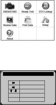
3.7 DTC Lookup
The DTC Lookup function is used to search for definitions of DTCs stored in the DTC library and for Code Breaker information.
1.From Main Screen (See Figure 3.1), use the Up/ Down scroll button and Left/Right scroll button to select DTC Lookup and press the OK button.
Figure 3.1
2.From DTC Lookup screen, use the Left/Right button to move to the desired character, use the Up/Down button to change selected digit/character and press the OK button to confirm.
DTC Lookup
P 0 0 0 1
Left
Right
Change digit
OK Confirm
ESC Exit
Figure 3.2
Item 60693 For technical questions, please call 1-888-866-5797. |
Page 17 |
3.View the DTC definition on screen. When the DTC definition covers more than one screen, use the Left/Right button or Up/Down button to view additional information on previous/next screens.
a.For manufacturer specific codes, you need to select a vehicle make on an additional screen to look for DTC definitions.
b.If definition could not be found (SAE or Manufacturer Specific), the Scan Tool displays “Please refer to vehicle's User's Manual!”
c.For Code Breaker information, you need to press the “?” Help button.
d.In the Code Breaker screen, there are three options to assist user to understand DTC more:
•System Description to read detailed description of DTCs
•Quick Check to read detailed description of DTCs
•General Notes to view helpful repair information of DTCs.
4.To view previous or next DTC in the built-in DTC library, use the Left/Right button.
5.To enter another DTC, press the ESC button to return to previous screen.
6.To exit to Main Screen, press the ESC button.
3.8 System Setup
The Scan Tool allows you to make the following adjustments and settings:
1.Language: Selects the desired language.
2.Configure Monitors: Sets the monitors you want to test.
Page 18 |
For technical questions, please call 1-888-866-5797. Item 60693 |

3.Unit of measure: Sets the unit of measure to English or Metric.
4.Key Beep Set: Turns on/off beep.
5.Status Beep Set: Turns on/off the I/M Readiness Status beep.
6.Tool Self-test: Checks if the LCD display, LED lamps and keyboard are working normally.
7.Update Mode: Accesses the Update Mode.
• Settings of the unit will remain until change to the existing settings is made.
To Enter the Setup Menu
From the Main Screen (See Figure 3.1): Use the Up/Down scroll button and Left/Right scroll button to select Setup, and press the OK button. Follow the instructions to make adjustments and settings as described in the above setup options.
System Setup |
1/7 |
Language
Configure Monitors ?
Unit of Measure
Key Beep Set
Status Beep Set
Tool Self-test
Figure 3.3
Language Setup
•English is the default language.
1.From System Setup screen, use the Up/Down scroll button to select Language, and press the OK button.
Item 60693 For technical questions, please call 1-888-866-5797. |
Page 19 |

2.Use the Up/Down scroll button to select the desired language and press the OK button to save your selection and return to previous screen.
|
|
|
|
|
|
|
Language |
1/3 |
|
|
|
|
|
|
|
|
English |
|
|
|
|
Français |
? |
|
|
|
Español |
|
|
|
|
|
|
|
Figure 3.4
Configure Monitors
From System Setup screen, use the Up/Down scroll button to select Configure Monitors, and press the OK button.
In this menu, you can configure the monitors required to test spark ignition and compression ignition, the number of monitors to pass diagnosis, and restore the default settings. (See Figure 3.5)
Configure Monitors 1/4
Spark IGN Required Monitors
Compression IGN Required Monitors
Allowed INC Monitors |
? |
Reset Factory Default |
|
Figure 3.5
Page 20 |
For technical questions, please call 1-888-866-5797. Item 60693 |
Spark IGN (Gasoline) Required Monitors
From Configure Monitors screen, use the Up/Down scroll button to select Spark IGN Required Monitors, and press the OK button. The monitors for spark ignition engines show as below:
Spark IGN Required Monitors
√ |
MIS |
√ |
EVAP |
√ |
FUEL |
√ |
AIR |
√ |
CCM |
√ |
O2S |
√ |
CAT |
√ |
HTR |
√ |
HCAT |
√ |
EGR |
Compression IGN (Diesel) Required Monitors
From Configure Monitors screen, use the Up/ Down scroll button to select Compression IGN Required Monitors, and press the OK button.
The monitors for compression ignition engines show as below:
Compression IGN Required Monitors
√ |
MIS |
√ |
BP |
√ |
FUEL |
√ |
EGS |
√ |
CCM |
√ |
PM |
√ |
HCCAT |
√ |
EGR |
√NCAT
Allowed INC Monitors
From Configure Monitors screen, use the Up/Down scroll button to select Allowed INC Monitors, and press the OK button.
Item 60693 For technical questions, please call 1-888-866-5797. |
Page 21 |
 Loading...