


Owner’s Manual & Safety Instructions
Save This Manual Keep this manual for the safety warnings and precautions, assembly, operating, inspection, maintenance and cleaning procedures. Write the product’s serial number in the back of the manual near the assembly diagram (or month and year of purchase if product has no number). Keep this manual and the receipt in a safe and dry place for future reference.
ITEM 69302 / 69305
SHALLOW WELL
PUMP
|
|
|
|
|
|
|
|
|
ITEM 69302 |
ITEM 69305 |
|
Visit our website at: http://www.harborfreight.com
Email our technical support at: tech@harborfreight.com
When unpacking, make sure that the product is intact and undamaged. If any parts are missing or broken, please call 1-800-444-3353 as soon as possible.
Copyright© 2011 by Harbor Freight Tools®. All rights reserved.
No portion of this manual or any artwork contained herein may be reproduced in any shape or form without the express written consent of Harbor Freight Tools. Diagrams within this manual may not be drawn proportionally. Due to continuing improvements, actual product may differ slightly from the product described herein.
Tools required for assembly and service may not be included.
Read this material before using this product. Failure to do so can result in serious injury. Save this manual.
WARNING
Important! For your own safety –
before starting to run the pump, please have the following items checked by an expert:
1.Risk of electric shock – This pump is supplied with a grounding conductor and grounding type attachment plug. To reduce the risk of
electric shock, connect only to a properly grounded, grounding-type receptacle.
2.Risk of electric shock – This pump has not been investigated for use in swimming pool areas.
3.The electrical connections must be protected from moisture.
4.If there is danger of flooding, the electrical connections must be taken to higher ground.
5.Circulation of caustic fluids, as well as the circulation of abrasive materials, must be avoided at all costs.
6.The pump must be protected from frost.
7.The pump must be protected from running dry.
8.Access by children should also be prevented with appropriate measures.
9.WARNING: Handling the Power Cord on this product will expose you to lead,
a chemical known to the State of California to cause cancer, and birth defects or other
reproductive harm. Wash hands after handling. (California Health & Safety Code § 25249.5, et seq.)
10.The warnings, precautions, and instructions discussed in this instruction manual cannot cover all possible conditions and situations that may occur. It must be understood by
the operator that common sense and caution are factors which cannot be built into this product, but must be supplied by the operator.
Grounding Instructions
To prevent electric shock and death from incorrect grounding wire connection Read and follow these instructions:
Check with a qualified electrician if you are in doubt as to whether the outlet is properly grounded. Do not modify the power cord plug provided with the tool.
Never remove the grounding prong from the plug. Do not use the tool if the power cord or plug is damaged. If damaged, have it repaired by a service facility before use. If the plug will not fit the outlet, have a proper outlet installed by a qualified electrician.
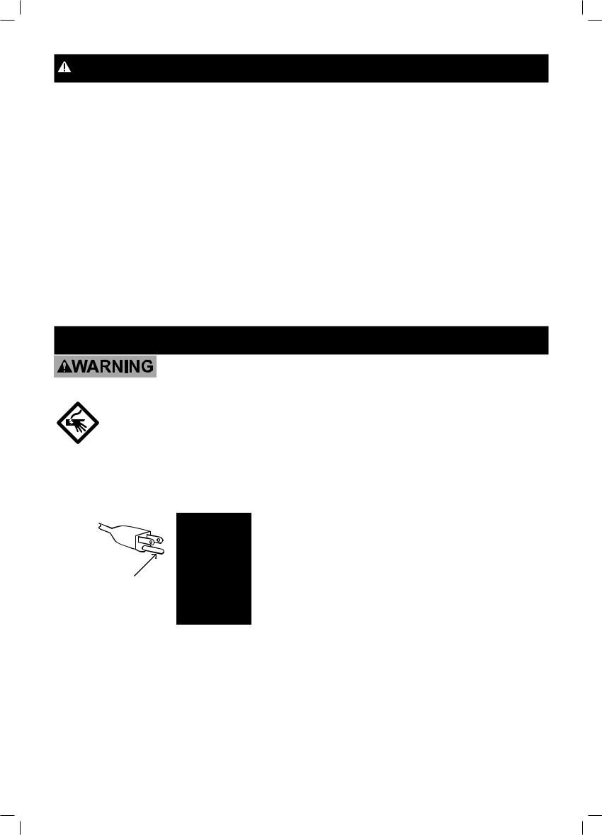
125 V~ 3-Prong Plug and Outlet (for up to 125 V~ and up to 15 A)
1. Tools marked with “Grounding Required” have a three wire cord and three prong grounding plug. The plug must be connected to a properly grounded outlet.
If the tool should electrically malfunction or break down, grounding provides a low resistance path to carry electricity away from the user, reducing the risk of electric shock. (See 3-Prong Plug and Outlet.)
Page 2 |
For technical questions, please call 1-800-444-3353. |
Item 69302 & 69305 |
Specifications
Model |
69302 |
69305 |
|
Electrical Rating |
120V~ 60Hz |
120V~ 60Hz |
|
4.5A |
4.5A |
||
|
|||
Inlet / Outlet Diameter |
1 IN. |
NPT |
|
Maximum Flow |
920 GPH |
||
Maximum Suction Lift |
26 FT. |
||
Maximum Delivery Height |
98 FT. |
||
Pump Body Material |
Stainless Steel |
Cast Iron |
|
Air Bladder Pressure |
23 |
PSI |
|
Start Pressure |
20 PSI |
||
Stop Pressure |
35 PSI |
||
Power Cord Length |
6 FT. |
||
NOT FOR POTABLE WATER.
Note: Performance of this pump (if powered by line voltage) may vary depending on variations in local line voltage. Extension cord usage may also affect pump performance.
Before start up, note the following: The pump can be connected to any shock proof plug which has been installed according to regulations. The plug must have a supply voltage of 120V~, 60Hz.
CAUTION: This pump has been evaluated for use with water only.
Fluid Type: The Pump is designed for use with water with a maximum temperature of 77° F (25° C). Do not use the pump for other fluids, especially not fuels, cleaning fluids, or other chemical products.
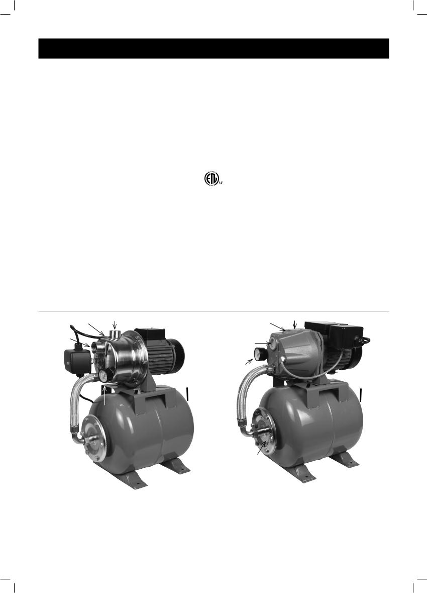
Components
Priming |
Discharge |
|
Priming Discharge |
Inlet |
|
|
Inlet |
Intake |
|
Intake |
|
|
|
|
|
|
Air |
Pressure |
Air |
|
Gauge |
||
|
Valve |
Valve |
|
|
(hidden) |
|
(hidden) |
|
Pressure |
|
|
|
Gauge |
|
|
Figure A: 69302 Components |
Figure B: 69305 Components |
Item 69302 & 69305 |
For technical questions, please call 1-800-444-3353. |
Page 3 |
Installation
The well motor pump must be installed in a stationary position with a fixed pipeline and a steady water supply.
Please note!
1.Do not install the pump by suspending it unsupported from its delivery pipe.
The pump must be placed on the bottom of the shaft.
2.The pump must be installed with an automatic float switch (not included) to prevent running dry.
Power Supply
1.The pump is equipped with a shock-proof plug according to regulations. The pump is designed to be connected to 120V~, 60Hz safety socket.
2.Make sure that the socket is sufficiently secured and is in excellent condition.
3.When the plug is inserted into the socket the pump will be on standby.
WARNING! If the power cord or plug is damaged, do not use the pump. The power cord or plug may only be repaired by a certified electrician.
Installation Considerations
This pump is designed for use as a well pump.
WARNING! To prevent serious injury from electric shock:
Install indoors or in weather-proof well house only. This Pump is non-submersible.
Do not plug in the power cord when wet or standing on damp or wet ground.
Do not plug in the power cord until instructed to do so.
NOTE:
a.ONLY pump clean water.
b.Additional components (such as valves and pipes) may be required for installation, but not included.
c.Installation requires skilled workmanship and compliance with local building codes.
If you are not confident in your ability to properly and safely install this pump, have a qualified technician perform the installation.
d.The water to be pumped must be clean and must be free of sand and grit, which would damage the pump and void the warranty.
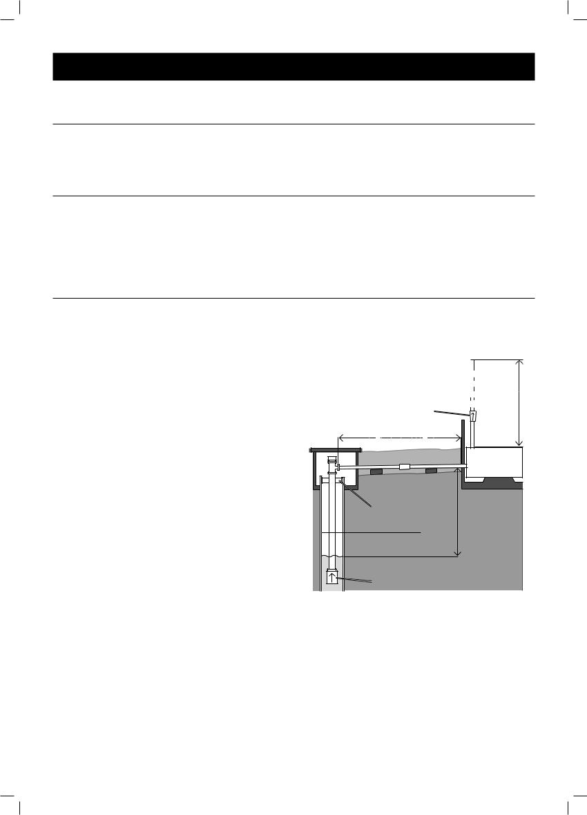
1.The illustration below shows an example of a proper shallow well pump installation. The total suction lift (vertical well lift + length of off set line) must
not exceed Maximum Suction Lift.
|
Outlet Water |
|
|
Level |
|
|
To |
|
|
Household |
|
Check |
Water |
Head |
System |
||
Valve |
|
|
Length of off-set line
(Add when calculating total suction lift due to friction.)
Slope slightly Downward to well |
Shallow |
|
|
|
Well Pump |
Well |
Lift |
|
Well |
|
|
Seal |
|
|
Vertical |
|
|
Standing Water Level |
|
|
(With Well Pump Off) |
|
|
Pumping Water Level (with Well Pump Operating) |
||
Foot |
|
|
Valve |
|
|
Figure C: Pump Setup Example
Note: This pump is intended for shallow well application only and is not intended to be used as a booster pump.
Note: For optimal performance, install the pump as close to the well head as possible.
2.Install a Foot Valve at the bottom of
the suction pipe. The Foot Valve must be under the Pumping Water Level, the level that the water falls to when the pump operates.
Page 4 |
For technical questions, please call 1-800-444-3353. |
Item 69302 & 69305 |
 Loading...