


45861

9” X 20” GEARED HEAD, BELT
DRIVEN, BENCH LATHE
Model
45861
SET UP AND OPERATING INSTRUCTIONS
Distributed exclusively by Harbor Freight Tools
®
.
3491 Mission Oaks Blvd., Camarillo, CA 93011
Visit our website at: http://www.harborfreight.com
Read this material before using this product.
Failure to do so can result in serious injury.
SAVE THIS MANUAL.
Copyright
©
2008 by Harbor Freight Tools
®
. All rights reserved. No portion of this manual or any
artwork contained herein may be reproduced in any shape or form without the express written
consent of Harbor Freight Tools. Diagrams within this manual may not be drawn proportionally. Due
to continuing improvements, actual product may differ slightly from the product described herein.
For technical questions or replacement parts, please call 1-800-444-3353.

Page 2SKU 45861 For technical questions, please call 1-800-444-3353.
CONTENTS
IMPORTANT SAFETY
INFORMATION ............................ 3
GENERAL POWER TOOL
SAFETY WARNINGS.......................3
LATHE SAFETY WARNINGS ............5
GROUNDING ................................. 6
GROUNDED TOOLS: TOOLS
WITH THREE PRONG PLUGS .......6
EXTENSION CORDS .........................7
SYMBOLOGY .....................................7
SPECIFICATIONS .......................... 9
UNPACKING .................................. 9
LIST OF CONTENTS ..........................9
INSTRUCTIONS FOR PUTTING
INTO USE .................................... 9
MOUNTING .........................................9
FUNCTIONS .....................................10
OPERATING INSTRUCTIONS .... 10
TOOL SET UP ..................................10
WORKPIECE AND WORK AREA
SET UP ..........................................10
SPINDLE SPEEDS ........................... 14
GENERAL OPERATING
INSTRUCTIONS ............................16
MAINTENANCE AND
SERVICING ............................... 19
CLEANING AND MAINTENANCE ... 19
LUBRICATION .................................. 19
HEADSTOCK PARTS LIST ......... 21
HEADSTOCK DIAGRAM ............. 21
DRIVE PARTS LIST ..................... 22
DRIVE DIAGRAM ........................ 23
TENSIONING ROLLER PARTS
LIST ........................................... 24
QUADRANT PARTS LIST ........... 25
MOTOR HOUSING PARTS LIST . 26
BED PARTS LIST ........................ 27
GEAR BOX PARTS LIST ............. 28
GEAR BOX DIAGRAM ................ 29
APRON PARTS LIST ................... 30
APRON PARTS LIST
CONTINUED .............................. 31
SADDLE AND CROSS SLIDE
PARTS LIST .............................. 32
SADDLE AND CROSS SLIDE
DIAGRAM .................................. 33
TAILSTOCK PARTS LIST ............ 34
TAILSTOCK DIAGRAM ............... 35
TRAVELLING REST PARTS
LIST ........................................... 36
STEADY REST PARTS LIST ....... 37
WIRING DIAGRAM ...................... 38
WIRING DIAGRAM ...................... 39
LIMITED 1 YEAR / 90 DAY
WARRANTY .............................. 40

Page 3SKU 45861 For technical questions, please call 1-800-444-3353.
SAVE THIS MANUAL
Keep this manual for the safety warn-
ings and precautions, assembly, operat-
ing, inspection, maintenance and cleaning
procedures. Write the product’s serial
number in the back of the manual near the
assembly diagram (or month and year of
purchase if product has no number). Keep
this manual and the receipt in a safe and
dry place for future reference.
IMPORTANT SAFETY
INFORMATION
In this manual, on the labeling,
and all other information
provided with this product:
This is the safety alert
symbol. It is used to alert
you to potential personal
injury hazards. Obey all
safety messages that
follow this symbol to avoid
possible injury or death.
DANGER indicates
a hazardous
situation which, if not
avoided, will result in death or
serious injury.
WARNING
indicates a
hazardous situation which, if
not avoided, could result in
death or serious injury.
CAUTION, used
with the safety
alert symbol, indicates a
hazardous situation which, if
not avoided, could result in
minor or moderate injury.
NOTICE is used to
address practices
not related to personal injury.
CAUTION, without
the safety alert
symbol, is used to address
practices not related to
personal injury.
General Power Tool Safety
Warnings
WARNING Read all safety
warnings and instructions.
Failure to follow the warnings and
instructions may result in electric
shock, re and/or serious injury.
Save all warnings and
instructions for future reference.
The term ″power tool″ in the
warnings refers to your mains-
operated (corded) power tool.
Work area safety1.
Keep work area clean and well lit. a.
Cluttered or dark areas invite acci-
dents.
Do not operate power tools in b.
explosive atmospheres, such as in
the presence of ammable liquids,
gases or dust. Power tools create
sparks which may ignite the dust or
fumes.
Keep children and bystanders c.
away while operating a power tool.
Distractions can cause you to lose
control.
Electrical safety2.
Power tool plugs must match the a.
outlet. Never modify the plug in
any way. Do not use any adapter
plugs with grounded power tools.

Page 4SKU 45861 For technical questions, please call 1-800-444-3353.
Unmodied plugs and matching out-
lets will reduce risk of electric shock.
Avoid body contact with grounded b.
surfaces such as pipes, radiators,
ranges and refrigerators. There is
an increased risk of electric shock if
your body is grounded.
Do not expose power tools to rain c.
or wet conditions. Water entering
a power tool will increase the risk of
electric shock.
Do not abuse the cord. Never d.
use the cord to unplug the power
tool. Keep cord away from heat,
oil, sharp edges or moving parts.
Damaged or entangled cords in-
crease the risk of electric shock.
If operating a power tool in a damp e.
location is unavoidable, use a
Ground Fault Circuit Interrupter
(GFCI) protected supply. Use of
a GFCI reduces the risk of electric
shock.
Personal safety3.
Stay alert, watch what you are do-a.
ing and use common sense when
operating a power tool. Do not use
a power tool while you are tired
or under the inuence of drugs,
alcohol or medication. A moment
of inattention while operating power
tools may result in serious personal
injury.
Use safety equipment. Always b.
wear ANSI-approved eye protec-
tion. Safety equipment such as dust
mask, full face shield, heavy-duty
work gloves, non-skid safety shoes,
hard hat, or hearing protection used
for appropriate conditions will reduce
personal injuries.
Remove any adjusting key or c.
wrench before turning the power
tool on. A wrench or a key left at-
tached to a rotating part of the power
tool may result in personal injury.
Do not overreach. Keep proper d.
footing and balance at all times.
This enables better control of the
power tool in unexpected situations.
Dress properly. Do not wear loose e.
clothing or jewelry. Keep your
hair, clothing and gloves away
from moving parts. Loose clothes,
jewelry or long hair can be caught in
moving parts.
If devices are provided for the con-f.
nection of dust extraction and col-
lection facilities, ensure these are
connected and properly used. Use
of these devices can reduce dust-
related hazards.
Power tool use and care4.
Do not force the power tool. Use a.
the correct power tool for your ap-
plication. The correct power tool will
do the job better and safer at the rate
for which it was designed.
Do not use the power tool if the b.
switch does not turn it on and off.
Any power tool that cannot be con-
trolled with the switch is dangerous
and must be repaired.
Disconnect the plug from the c.
power source before making any
adjustments, changing accesso-
ries, or storing power tools. Such
preventive safety measures reduce
the risk of starting the power tool ac-
cidentally.
Store idle power tools out of the d.
reach of children and do not allow
persons unfamiliar with the power

Page 5SKU 45861 For technical questions, please call 1-800-444-3353.
tool or these instructions to oper-
ate the power tool. Power tools are
dangerous in the hands of untrained
users.
Maintain power tools. Check for e.
misalignment or binding of moving
parts, breakage of parts and any
other condition that may affect the
power tool’s operation. If dam-
aged, have the power tool repaired
before use. Many accidents are
caused by poorly maintained power
tools.
Keep cutting tools sharp and f.
clean. Properly maintained cutting
tools with sharp cutting edges are
less likely to bind and are easier to
control.
Use the power tool, accessories g.
and tool bits etc. in accordance
with these instructions, taking into
account the working conditions
and the work to be performed. Use
of the power tool for operations differ-
ent from those intended could result
in a hazardous situation.
Service5.
Have your power tool serviced by a.
a qualied repair person using
only identical replacement parts.
This will ensure that the safety of the
power tool is maintained.
Lathe Safety Warnings
Maintain labels and nameplates on 1.
the tool. These carry important safety
information. If unreadable or miss-
ing, contact Harbor Freight Tools for a
replacement.
Do not run the Lathe without its cov-2.
ers and guards in place.
Use a brush or compressed air to 3.
remove metal shavings; never your
hands. The metal shavings will be
sharp.
The tool must always be tight within 4.
the tool post or chuck and adjusted
to limit projection from the post. This
will reduce the possibility of the tool
breaking or bending.
Avoid unintentional starting. Prepare 5.
to begin work before turning on the
tool.
Do not reach across the Lathe while it 6.
is running.
Industrial applications must follow 7.
OSHA guidelines.
Do not use the Lathe if it is off-bal-8.
ance, or the workpiece is not properly
centered.
Only feed workpiece into a cutting 9.
tool against the direction of rotation.
Do not leave the tool unattended 10.
when it is plugged into an electrical
outlet. Turn off the tool, and unplug it
from its electrical outlet before leav-
ing.
This product is not a toy. Keep it out 11.
of reach of children.
People with pacemakers should 12.
consult their physician(s) before use.
Electromagnetic elds in close prox-
imity to heart pacemaker could cause
pacemaker interference or pacemak-
er failure. In addition, people with
pacemakers should:
• Avoid operating alone.
• Do not use with power switch locked
on.
• Properly maintain and inspect to
Page 6SKU 45861 For technical questions, please call 1-800-444-3353.
avoid electrical shock.
• Any power cord must be properly
grounded. Ground Fault Circuit Inter-
rupter (GFCI) should also be imple-
mented – it prevents sustained elec-
trical shock.
Some dust created by power sand-13.
ing, sawing, grinding, drilling, and
other construction activities, contains
chemicals known [to the State of Cali-
fornia] to cause cancer, birth defects
or other reproductive harm. Some
examples of these chemicals are:
• Lead from lead-based paints
• Crystalline silica from bricks and ce-
ment or other masonry products
• Arsenic and chromium from chemi-
cally treated lumber
Your risk from these exposures var-
ies, depending on how often you do
this type of work. To reduce your
exposure to these chemicals: work in
a well ventilated area, and work with
approved safety equipment, such as
those dust masks that are specially
designed to lter out microscopic
particles. (California Health & Safety
Code § 25249.5, et seq.)
The warnings, precautions, and in-14.
structions discussed in this instruction
manual cannot cover all possible con-
ditions and situations that may occur.
It must be understood by the operator
that common sense and caution are
factors which cannot be built into this
product, but must be supplied by the
operator.
SAVE THESE
INSTRUCTIONS.
GROUNDING
TO PREVENT
ELECTRIC SHOCK
AND DEATH FROM
INCORRECT GROUNDING
WIRE CONNECTION:
Check with a qualied
electrician if you are in doubt
as to whether the outlet is
properly grounded. Do not
modify the power cord plug
provided with the tool. Never
remove the grounding prong
from the plug. Do not use the
tool if the power cord or plug
is damaged. If damaged, have
it repaired by a service facility
before use. If the plug will not
t the outlet, have a proper
outlet installed by a qualied
electrician.
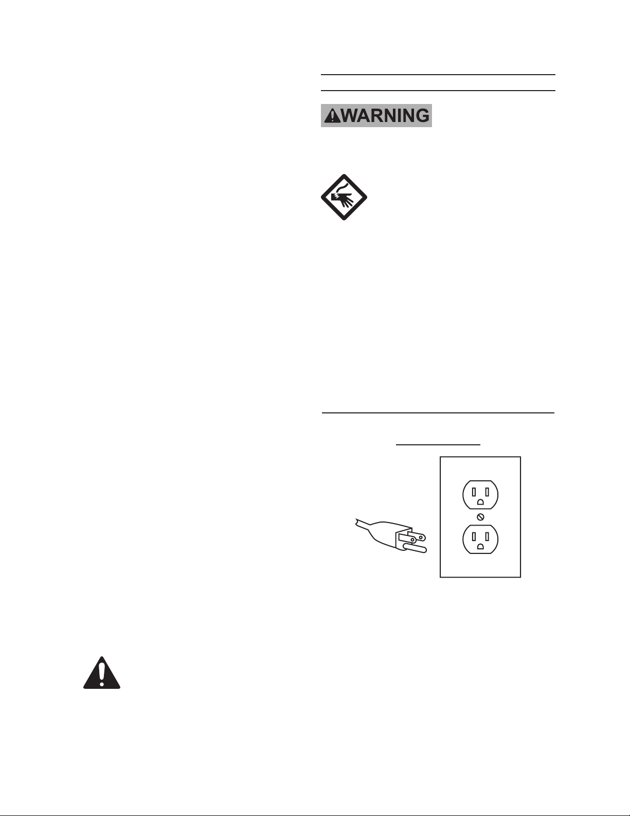
Grounded Tools: Tools with Three
Prong Plugs
3-Prong Plug and Outlet
1. Tools marked with “Grounding Re-
quired” have a three wire cord and
three prong grounding plug. The
plug must be connected to a properly
grounded outlet. If the tool should
electrically malfunction or break
down, grounding provides a low
resistance path to carry electricity
away from the user, reducing the risk

Page 7SKU 45861 For technical questions, please call 1-800-444-3353.
of electric shock. (See 3-Prong Plug
and Outlet.)
The grounding prong in the plug is 2.
connected through the green wire in-
side the cord to the grounding system
in the tool. The green wire in the cord
must be the only wire connected to
the tool’s grounding system and must
never be attached to an electrically
“live” terminal. (See 3-Prong Plug
and Outlet.)
The tool must be plugged into an 3.
appropriate outlet, properly installed
and grounded in accordance with all
codes and ordinances. The plug and
outlet should look like those in the
preceding illustration. (See 3-Prong
Plug and Outlet.)
Extension Cords
Grounded1. tools require a three wire
extension cord. Double Insulated
tools can use either a two or three
wire extension cord.
As the distance from the supply outlet 2.
increases, you must use a heavier
gauge extension cord. Using exten-
sion cords with inadequately sized
wire causes a serious drop in voltage,
resulting in loss of power and pos-
sible tool damage.
(See Table A.) The smaller the
gauge number of the wire, the greater
the capacity of the cord. For ex-
ample, a 14 gauge cord can carry a
higher current than a 16 gauge cord.
(See Table A.)
When using more than one exten-3.
sion cord to make up the total length,
make sure each cord contains at
least the minimum wire size required.
(See Table A.)
If you are using one extension cord 4.
for more than one tool, add the
nameplate amperes and use the sum
to determine the required minimum
cord size. (See Table A.)
If you are using an extension cord 5.
outdoors, make sure it is marked with
the sufx “W-A” (“W” in Canada) to
indicate it is acceptable for outdoor
use.
Make sure the extension cord is prop-6.
erly wired and in good electrical con-
dition. Always replace a damaged
extension cord or have it repaired by
a qualied electrician before using it.
Protect the extension cords from 7.
sharp objects, excessive heat, and
damp or wet areas.
RECOMMENDED MINIMUM WIRE
GAUGE FOR EXTENSION CORDS*
(120/240 VOLT)
NAMEPLATE
AMPERES
(at full load)
EXTENSION CORD
LENGTH
25’
50’
75’
100’
150’
0 – 2.0 18 18 18 18 16
2.1 – 3.4 18 18 18 16 14
3.5 – 5.0 18 18 16 14 12
5.1 – 7.0 18 16 14 12 12
7.1 – 12.0 18 14 12 10 -
12.1 – 16.0 14 12 10 - -
16.1 – 20.0 12 10 - - -
TABLE A
* Based on limiting the line
voltage drop to ve volts at
150% of the rated amperes.
Symbology
Double Insulated
Canadian Standards Association

Page 8SKU 45861 For technical questions, please call 1-800-444-3353.
Symbology
Underwriters Laboratories, Inc.
V~
Volts Alternating Current
A
Amperes
n
0
xxxx/min.
No Load Revolutions per Minute
(RPM)

Page 9SKU 45861 For technical questions, please call 1-800-444-3353.
SPECIFICATIONS
Electrical Requirements 120 V~ / 60 Hz
Lathe Type Metal Cutting
Motor 3/4 HP
Motor Speed 1790 RPM
Spindle Speed
120, 320, 420, 620,
1130 & 2000
Spindle Taper MT-3
Spindle Bore 3/4”
Chuck 3 Jaw
Chuck Capacity 4”
Tail Stock Quill Travel 1-3/4”
Tail Stock Quill Taper MT-2
Tool Post Capacity 3/4”
Swing Over Bed 9”
Distance Between Centers 20”
UNPACKING
When unpacking, check to make sure
that the item is intact and undamaged. If
any parts are missing or broken, please
call Harbor Freight Tools at the number
shown on the cover of this manual as soon
as possible.
Proper lubrication is essential. To
be safe, and to become more familiar with
the Lathe, disassemble the lathe entirely,
then clean and lubricate each part with
white lithium grease before rst use.
List of contents
Part(s) Description Qty
9” X 20” Bench Lathe 1
4” 3-Jaw Chuck 1
Reverse Jaws For Chuck. 3
Chuck Wrench 1
Dead Center Mt#2 1
Dead Center Mt#3 1
Live Center 1
10-12 Open-End Wrench 1
14-17 Open-End Wrench 1
Part(s) Description Qty
17-19 Open-End Wrench 1
Round Nut Wrench 45-52 1
Tool Post Wrench 1
Hex Wrenches - 3, 4, 5, 6mm 1 ea.
Drive Belts 2
Threading Gear Set 28,30,
36,42,45 & 80T
1
Oil Can 1
Splash Guard 1
Operators Manual 1
INSTRUCTIONS FOR
PUTTING INTO USE
Read the ENTIRE IMPORTANT
SAFETY INFORMATION section
at the beginning of this manual
including all text under
subheadings therein before set
up or use of this product.
TO PREVENT
SERIOUS INJURY
FROM ACCIDENTAL
OPERATION:
Turn the Power Switch of the
tool to its “OFF” position and
unplug the tool from its
electrical outlet before
assembling or making any
adjustments to the tool.
Note: For additional information regarding
the parts listed in the following pages,
refer to the Assembly Diagram near
the end of this manual.
Mounting
Unbolt and remove the Lathe from 1.
the crate.
The Lathe will need to be mounted 2.
to a surface capable of bearing the
combined weight of the Lathe and
intended workpieces. The surface

Page 10SKU 45861 For technical questions, please call 1-800-444-3353.
must be able to withstand the vibra-
tion generated by the Lathe during
operation. The cabinet recommend-
ed for use with this Lathe is SKU
46378; this product is available from
Harbor Freight Tools.
Use a hoist or a forklift to lift the 3.
Lathe onto the cabinet or workbench.
Mount the Spacer Blocks. The Lathe 4.
must be completely level, left-to-right
and front-to-back, or the Lathe will
not mill properly and may become
damaged.
Mount the dip tray.5.
Thread on the belt tensioner lever.6.
The unpainted surfaces are coated 7.
with a waxy oil to protect them from
corrosion during shipment. Remove
the coating with a solvent cleaner or
citrus-based degreaser. Avoid chlo-
rine-based solvents since they will
damage the paint.
When connecting
or removing the
chuck, take care to protect the
ways by placing a piece of
wood, or other guard, over
them. Damaging the ways
may permanently disable the
lathe.
Functions
The Lathe can be used to shape 1.
metal, make screws, and bore screw
threads.
OPERATING INSTRUCTIONS
Read the ENTIRE IMPORTANT
SAFETY INFORMATION section
at the beginning of this manual
including all text under
subheadings therein before set
up or use of this product.
Tool Set Up
TO PREVENT
SERIOUS INJURY
FROM ACCIDENTAL
OPERATION:
Turn the Power Switch of the
tool to its “OFF” position and
unplug the tool from its
electrical outlet before
performing any inspection,
maintenance, or cleaning
procedures.
Settings for the spindle, chuck, gibs, 1.
ways, and ends, will be determined
by the length of the stock and the
intended operation.
The Lathe speed must be set to “0” 2.
before restarting.
Workpiece and Work Area Set Up
Designate a work area that is clean 1.
and well-lit. The work area must not
allow access by children or pets to
prevent injury and distraction.
Route the power cord along a safe 2.
route to reach the work area without
creating a tripping hazard or exposing
the power cord to possible damage.
Secure loose workpieces to prevent 3.
movement while working.
Page 11SKU 45861 For technical questions, please call 1-800-444-3353.
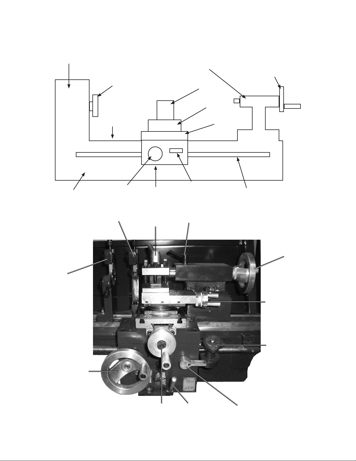
Lathe
Headstock
Faceplate (or chuck)
Bed
Ways
Cross Slide
Compound
Tool Holder
Tailstock Tailstock
Handwheel
Carriage
Halfnut
Lever
Leadscrew
Carriage
Handwheel
Steady
Rest
Follow Rest
Tool
Lock
Tailstock Lock
Tailstock
Handwheel
Handrail
Tool
Thread
Indicator
Gear Engage
Gear
Lock
Cross Slide
Handwheel
Apron
Handwheel

Page 12SKU 45861 For technical questions, please call 1-800-444-3353.
Denition of Terms
Apron: The front part of the carriage
assembly where the carriage hand-
wheel is mounted.
Bed: Main supporting casting run-
ning the length of the lathe
Between Centers: A dimension
representing the maximum length
of a workpiece that can be turned
between centers. Also a method of
holding a workpiece by mounting it
between the centers of the headstock
and the tailstock spindles.
Carriage: The assembly that moves
the tool post and cutting tool along
the ways.
Carriage Handwheel: A wheel with
a handle used to move the carriage
by hand.
Center: A precision ground tapered
cylinder with a 60º pointed tip and
a Morse Taper shaft. Used in the
tailstock to support the end of long
workpieces. May also be used in the
headstock spindle to support work
between centers at both ends.
Center Drill: A short drill used to
form pilot holes and countersunk
holes.
Centerline: An imaginary line ex-
tending from the center of the spindle
through the center of the tailstock
ram, representing the central axis
of the lathe around which the work
rotates.
Chuck: A clamping device for hold-
ing work in the lathe or for holding
drills in the tailstock.
Compound: Movable platform
where the tool post is mounted; it can
be set at an angle to the workpiece
(also known as compound slide and
compound rest).
Compound Handwheel: The wheel
used to move the compound slide in
and out.
Cross Slide: Platform that moves
along the lathe axis under control of
the cross-slide handwheel.
Cross Slide Handwheel: The wheel
used to move the cross slide in and
out (also called cross feed).
Faceplate: A metal plate with a at
face-mounted spindle to hold irregu-
larly shaped work.
Facing: A lathe operation in which
metal is removed from the end of a
workpiece to create a smooth sur-
face.
Gib: An adjustable length of steel or
brass with a diamond shaped cross-
section that engages one side of the
dovetail slide. Used to adjust the
dovetail for optimum tightness and to
compensate for wear.
Halfnut: A nut formed from two
halves which clamp around the lead-
screw to move the carriage.
Halfnut Lever: This Lever engages
the carriage with the leadscrew.
Headstock: The main casting
mounted on the left end of the bed
where the spindle is mounted. Hous-
es the spindle gears.
Leadscrew: Screw used to drive the
carriage under power for turning and
thread cutting operations. Smaller
 Loading...