


Instruction Manual
BL 7916 • BL 7917
pH and ORP
Measuring & Dosing
System
w w w . h a n n a i n s t . c o m

Dear Customer,
Thank you for choosing a Hanna product.
Please read this instruction manual carefully before using the pump. If you need additional technical information, do not hesitate to e-mail us at tech@hannainst.com.
These instruments are in compliance with the 
 directives.
WARRANTY
All Hanna Instruments pumps are warranted for one year against defects in workmanship and materials when used for their intended purpose and maintained according to instructions. This warranty is limited to repair or replacement free of charge. Damages due to accident, misuse, tampering or lack of prescribed maintenance are not covered. If service is required, contact the dealer from whom you purchased the instrument. If under warranty, report the model number, date of purchase, serial number and the nature of the failure. If the repair is not covered by the warranty, you will be notified of the charges incurred. If the instrument is to be returned to Hanna Instruments, first obtain a Returned Goods Authorization Number from the Customer Service department and then send it with shipment costs prepaid. When shipping any instrument, make sure it is properly packaged for complete protection.
TABLE OF CONTENTS |
|
PRELIMINARY EXAMINATION ........................................................ |
3 |
GENERAL DESCRIPTION ................................................................ |
4 |
FLOW RATE CHART ....................................................................... |
5 |
FUNCTIONAL DESCRIPTION BL 7916 ............................................ |
6 |
FUNCTIONAL DESCRIPTION BL 7917 ............................................ |
7 |
SPECIFICATIONS........................................................................... |
8 |
VALVE / HOSE ASSEMBLY DIAGRAM ............................................. |
9 |
MECHANICAL DIMENSIONS ........................................................ |
10 |
INSTALLATION ........................................................................... |
11 |
OPERATIONAL GUIDE ................................................................. |
18 |
pH CALIBRATION ....................................................................... |
22 |
TROUBLESHOOTING GUIDE ........................................................ |
23 |
MAINTENANCE ........................................................................... |
24 |
ELECTRODE CONDITIONING AND MAINTENANCE ........................... |
26 |
TAKING REDOX MEASUREMENTS ................................................. |
30 |
CHEMICAL COMPATIBILITY GUIDE................................................ |
32 |
ACCESSORIES ............................................................................. |
34 |
CE DECLARATION OF CONFORMITY .............................................. |
38 |
PRELIMINARY EXAMINATION
Remove the pump from the packing material and examine it carefully to make sure that no damage has occurred during shipping. If there is any noticeable damage, notify your Dealer.
Each pump is supplied complete with:
•discharge and suction valves
•LDPE tubing, 7 m (23')
•power cord
•instruction manual
Note: Save all packing material until you are sure that the pump functions correctly. Any defective item must be returned in the original packaging together with the supplied accessories.
READ THE INSTRUCTIONS ATTENTIVELY
BEFORE INSTALLING OR OPERATING YOUR PUMP
The BL electronic dosing pumps are easy to use. We recommend, however, that you read the entire manual before using the pump. Familiarity with the features and controls of the unit will give you a better idea of the dosing potential and help reduce operator errors. Please operate the pump only as directed in the instruction manual. Follow all general safety guidelines during operation.
Remember: electrical devices are potentially hazardous. Check that the voltage of the installation matches the voltage indicated on the specification label on the back of the pump.
Note: It is the responsibility of the user to install and ground the pump properly; it is highly recommended to install an external switch.
Each pump is protected by a 1 A/250 V fuse that is located together with 1 spare in a drawer on the power socket under the pump. Always store chemicals in safe, out of reach places. Follow the directions for use with each chemical. Do not assume chemicals are the same because they look alike. Hanna Instruments cannot be held responsible for the misuse of chemicals or the pump.
Always wear protective clothing (gloves and safety glasses) when working near chemical dosing pumps. When pumping chemicals, make sure all tubes are securely attached to the fittings. It is recommended that tubing is shielded to prevent possible injury in case of rupture or accidental damage.
Avoid using a pipe wrench or pliers on plastic parts and connectors.
2 |
3 |
These are best tightened with an open end or crescent wrench. Avoid overtightening these parts as this could cause damage to the seats and threads.
If a hose is used, it should be securely fastened to columns, walls, braces, etc. This will ensure that the hose connection will remain tight and leak free. Shield the hose from direct sunlight. Sunlight can cause an autocatalytic reaction with some chemicals and weaken the hose walls.
The arrow on the pump head indicates the direction of chemical flow and should always point upwards (vertically). Never position the pump horizontally with suction and discharge valves horizontal. Locate the pump in an area out of the reach of children and pets. All pumps undergo stringent tests to ensure that they comply with their stated specifications and are calibrated at the maximum rated pressure.
Unplug the instrument from the power supply before replacing the fuse or making any electrical connections.
GENERAL DESCRIPTION
The BL 7916 and BL 7917 Control/Pump System offer respectively a pH and ORP monitoring system with proportional control of a diaphragm pump and an LCD readout.
Features include:
•Two advanced instruments in one compact unit
•Proportional control for precisely maintained set-points
•Rugged construction with a one-piece casing and a transparent cover to protect controls and terminals
•Chemically resistant non-clogging pump head and superior materials for all components in contact with the chemicals being dosed (see page 32 for details)
•Convenient installation with all controls on front panel
•A solenoid-driven pump
•Automatic overheat protection and a built-in LCD display
•Alarm output: the alarm of the BL 7916 will be activated if the measured pH value is 2 pH units higher or lower than the setpoint. BL 7917's alarm will activate if the mV value is 200mV higher or lower than the setpoint.
•Auxiliary dosing contacts. This will drive other equipment such as mixers, priming pumps, etc.
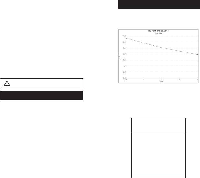
FLOW RATE CHART
The following chart shows the inverse relationship between flow rate and pressure.
The table below shows typical reduction of the flow rate with an increase of pressure. The pump supplied with the system has a capacity of 13.3 LPH (3.5 GPH) at 0.5 BAR (7.4 PSI).
BL 7916 / BL 7917
FLOW / PRESSURE
BAR (PSI) |
LPH (GPH) |
|
|
0.5 (7.4) |
13.3 (3.46) |
|
|
1.0 (14.7) |
11.7 (3.04) |
|
|
2.0 (29.4) |
10.1 (2.63) |
|
|
3.0 (44.1) |
9.0 (2.33) |
|
|
4.0 (58.8) |
7.8 (2.03) |
4 |
5 |

FUNCTIONAL DESCRIPTION BL 7916 |
|
FUNCTIONAL DESCRIPTION BL 7917 |
|||||||||||||||||||||||||
|
|
|
|
|
|
|
|
|
|
|
|
|
|
|
|
|
|
|
|
|
|
|
|
|
|
|
|
|
|
|
|
|
|
|
|
|
|
|
|
|
|
|
|
|
|
|
|
|
|
|
|
|
|
|
|
|
|
|
|
|
|
|
|
|
|
|
|
|
|
|
|
|
|
|
|
|
|
|
|
|
|
|
|
|
|
|
|
|
|
|
|
|
|
|
|
|
|
|
|
|
|
|
|
|
|
|
|
|
|
|
|
|
|
|
|
|
|
|
|
|
|
|
|
|
|
|
|
|
|
|
|
|
|
|
|
|
|
|
|
|
|
|
|
|
|
|
|
|
|
|
|
|
|
|
|
|
|
|
|
|
|
|
|
|
|
|
|
|
|
|
|
|
|
|
|
|
|
|
|
|
|
|
|
|
|
|
|
|
|
|
|
|
|
|
|
|
|
|
|
|
|
|
|
|
|
|
|
|
|
|
|
|
|
|
|
|
|
|
|
|
|
|
|
|
|
|
|
|
|
|
|
|
|
|
|
|
|
|
|
|
|
|
|
|
|
|
|
|
|
|
|
1.Discharge Valve Assembly
2.Pump head
3.Suction Valve Assembly
4.Hose
5.Liquid Crystal Display
6.Offset Calibration Trimmer
7.Setpoint Adjustment Trimmers (FINE and COARSE)
8.Slope Calibration Trimmer
9.Acid/Base Selection Switch
10.Display Mode Selection Switch (SET or MEASURE)
11.Terminal Connections
12.BNC Connector for pH electrode
13.Overheating LED
14.Power Socket and Fuse Holder
15.Cable Glands
Unplug the instrument from the power supply before replacing the fuse or making any electrical connections.
1.Discharge Valve Assembly
2.Pump head
3.Suction Valve Assembly
4.Hose
5.Liquid Crystal Display
6.Setpoint Adjustment Trimmers (FINE and COARSE)
7.Reduction/Oxidation Selection Switch
8.Operating Mode Selection Switch (SET or MEASURE)
9.Terminal Connections
10.BNC Connector for ORP electrode
11.Overheating LED
12.Power Socket and Fuse Holder
13.Cable Glands
Unplug the instrument from the power supply before replacing the fuse or making any electrical connections.
6 |
7 |
SPECIFICATIONS
|
BL 7916D |
|
BL 7916U |
|
|
|
|
Range |
0.00 to 14.00 pH |
||
|
|
|
|
Resolution |
|
0.01 pH |
|
|
|
|
|
Accuracy (@20°C/68°F) |
|
±0.01 pH |
|
|
|
|
|
Typical EMC Deviation |
|
±0.1 pH |
|
InputImpedance |
|
10¹² Ohm |
|
|
|
|
|
Dosage |
Proportional, acid or base, user selectable |
||
|
|
|
|
DosingContact |
Isolated, 2A, Max. 240V, resistive load, 1,000,000 strokes |
||
|
|
|
|
Alarm Contact |
Isolated, 2A, Max. 240V, resistive load, 1,000,000 strokes |
||
|
|
|
|
Calibration |
Offset: ±1 pH with trimmer |
||
|
Slope: 85 to 115% with trimmer |
||
|
|
|
|
RecorderOutput |
4 to 20 mA (isolated) |
||
|
|
|
|
Power Supply |
230 Vac ±15% |
|
115 Vac ±15% |
|
50/60 Hz (40 W) |
|
50/60 Hz (40 W) |
|
|
|
|
Environment |
0 to 50°C (32 to 122°F); |
||
|
RH max 95% non-condensing |
||
Dimensions |
221 x 142 x 181 mm (8.7 x 5.6 x 7.1'') |
||
|
|
||
Weight |
Approximately 5 kg (11 lb.) |
||
|
|
|
|
|
|
|
|
|
BL 7917D |
|
BL 7917U |
|
|
|
|
Range |
-999 to +999 mV |
||
|
|
|
|
Resolution |
|
1 mV |
|
|
|
|
|
Accuracy (@20°C/68°F) |
|
±5 mV |
|
|
|
|
|
Typical EMC Deviation |
|
±6 mV |
|
|
|
|
|
InputImpedance |
|
10¹² Ohm |
|
|
|
||
Dosage |
Proportional, oxidizing or reducing, user selectable |
||
|
|
||
DosingContact |
Isolated, 2A, Max. 240V, resistive load, 1,000,000 strokes |
||
|
|
||
Alarm Contact |
Isolated, 2A, Max. 240V, resistive load, 1,000,000 strokes |
||
|
|
||
RecorderOutput |
4 to 20 mA (isolated) |
||
|
|
|
|
Power Supply |
230 Vac ±15% |
|
115 Vac ±15% |
|
50/60 Hz (40 W) |
|
50/60 Hz (40 W) |
|
|
|
|
Environment |
0 to 50°C (32 to 122°F); |
||
|
RH max 95% non-condensing |
||
Dimensions |
221 x 142 x 181 mm (8.7 x 5.6 x 7.1) |
||
Weight |
Approximately 5 kg (11 lb.) |
||
|
|
|
|
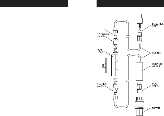
VALVE / HOSE ASSEMBLY DIAGRAM
NECK
8 |
9 |
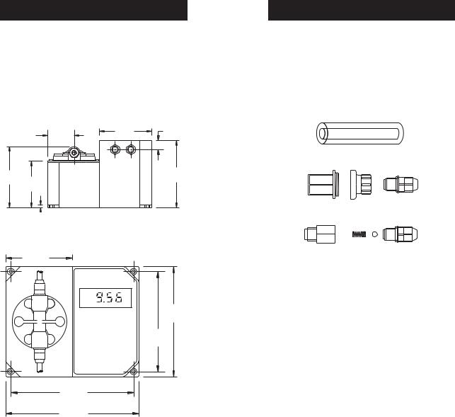
MECHANICAL DIMENSIONS
The Controller/Pump series of instruments are enclosed in a modular housing for maximum protection. The dimensioned illustrations show the layout of the Controller/Pumps and how they utilize the one-piece polypropylene, injection-molded housing. Since there are no joints or screws holding different sections of the housing together, the case is extremely rugged and sturdy.
BOTTOM VIEW
|
55mm |
110mm |
17mm |
|
4.33" |
.67" |
|
|
2.16" |
||
|
|
|
|
129mm |
|
|
142mm |
|
|
5.60" |
|
5.08" |
99mm |
|
|
|
|
||
|
3.90" |
|
|
5mm 0.19"
0.19"
FRONT VIEW
110mm
4.33"
pH
181mm
7.13"
164mm
6.45"
204mm
8.03"
221mm
8.70"
INSTALLATION
Materials Needed
•LDPE hose (7 meter/22 feet) (included) or other type of tubing (PTFE, for example) more suitable for a specific application (optional)
•Power cord (included)
Optional Accessories
•4 each, ceramic weights (HI 721008)
•1 each, foot valve assembly (HI 721005)
•1 each, injection valve assembly (HI 721004)
Location
A suitable location should:
•be near to a power source
•be conveniently close to the injection point
•allow easy access to the flow rate control and pipe or hose connections
•be no more than 1.5 meters (5 feet) above the operating position of the suction valve assembly.
Dimensions for Installation
BlackStone Pumps are designed for permanent installation.
The pump can be mounted directly on a wall or tank (see page 10 for the specific mounting dimensions).
Power Requirements
BlackStone pumps are designed to operate to specifications within the following voltage ranges:
100 - 130 Volts for 115 Vac models
200 - 250 Volts for 230 Vac models
10 |
11 |
To ensure maximum performance, check the voltage at the point of supply to verify that it is sufficient. It is recommended that you install a 1 Amp circuit breaker between the pump and the power supply. This will give additional protection to the internal circuit and provide a convenient way to disconnect the power supply prior to servicing the pump, if needed.
Injection Point
•Choose an injection point that allows you to mount the injection valve assembly vertically.
•The spring in the injection valve assembly (HI 721004) adds approximately 1.5 bar of back pressure. If pumping into a high back pressure, the spring should be removed.
Other Considerations
•If you are mounting the system to a wall, column, etc., be sure it is strong enough to support the weight of the entire system.
•The ambient temperature of the pump, when in operation, should be between 0 and 50°C (32 to 122°F) and should be protected from direct exposure to outdoor elements (direct sunlight, rain, extreme temperatures, high humidity, etc.).
•Generally speaking, the shorter the suction distance, the more efficient the pump operates.
•The pump should be placed in a conventional location that will allow easy access to the control and connections. It should be placed so that regular visual inspections of the connections and hoses are facilitated.
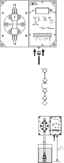
Vertical Surface Mounting
Once you have selected the best installation site, simply screw or bolt the unit into a wall or mounting panel above the chemical feed tank. The 4 mounting screw holes on the pump will accommodate up to a 5 mm (3/16") screw or bolt (remember to use heavy screws or bolts to secure the system). Be sure you do not over tighten and cause excessive stress on the mounting holes.
Make sure to leave a slight overhang in front to allow for the connection cable.
Power Supply
Connect the power cord to the female socket of the pump and by doing so also grounding it. The power socket contains a 1 A/250 V fuse. Since there is no on/off switch, it is suggested to install an outside switch.
Probe connections
Connect the pH/ORP electrode to the BNC socket of the pump.
Permanent Connection using 3/8" PVC pipe
All piping for the pump feed and discharge should be plumbed to the location of the pump.
The threads on both valve assemblies allow the use of standard 3/8" (European) pipe fittings for permanent pipe connections.
The foot valve assembly (HI 721005) should always hang vertically and not lay horizontal on the bottom of the tank or drum.
A vertical assembly will ensure that the valve is positioned properly and prevent loss of prime.
For the US standard installations, use PVC adapters to connect the suction and discharge valves to the PVC pipe.
UNIONCONNECTION
ADAPTER
DISCHARGE VALVE
PUMP
SUCTION VALVE
ADAPTER
FOOT VALVE
-FILTER
Diagram for Rigid Pipe Hose
12 |
13 |
 Loading...