


Installation Instructions
Built-In Dishwasher
If you have questions, call Haier Appliances at 877-337-3639 or visit our website at: haierappliances.com. In Canada, please call 800.561.3344.
BEFORE YOU BEGIN
Read these instructions completely and carefully.

 WARNING
•Remove all power leading to the appliance from the circuit breaker or fuse box before beginning installation. Failure to do so can result in a risk of electrical shock.
•To reduce the risk of electric shock, fire, or injury to persons, the installer must ensure that the dishwasher is completely enclosed at the time of installation.
•The improper connection of the equipment grounding conductor can result in a risk of electric shock. Check with a qualified electrician or service representative if you are in doubt that the appliance is properly grounded. If house wiring is not 2-wire with ground, a ground must be by the installer. When house wiring is aluminum,
be sure to use UL-Listed anti-oxidant compound and aluminum-to-copper connectors.
•To reduce the risk of electric shock, fire, or injury to persons, the installer should check to ensure that wires are not pinched or damaged, the house wiring is attached to the junction box bracket through a strain relief, and all electrical connections made at the time of install (wire nuts) are contained inside of the junction box cover.
•Do not use an extension cord or adapter plug with this appliance.
•Be sure to leave complete literature package, these Installation Instructions and product samples and/or coupons with the consumer.
NOTE: Product improvement is a continuing endeavor at Haier Appliances. Therefore, materials, appearance and specifications are subject to change without notice.
FOR YOUR SAFETY
Read and observe all WARNINGS and CAUTIONS shown throughout these instructions.
While performing installations described in this booklet, gloves and safety glasses or goggles should be worn.
IMPORTANT – Observe all governing codes and ordinances.
•Note to Installer – Be sure to leave these instructions for the consumer’s and local inspector’s use.
•Note to Consumer – Keep these instructions with your Owner’s Manual for future reference.
•Skill Level – Installation of this dishwasher requires basic mechanical, electrical and plumbing skills.
Proper installation is the responsibility of the installer. Product failure due to improper installation is not covered under the Haier Appliances Warranty. See Warranty information.
•Completion Time – 1 to 3 Hours. New installations require more time than replacement installations.
IMPORTANT – The dishwasher MUST be installed to allow for future removal from the enclosure if service is required.
Care should be exercised when the appliance is installed or removed, to reduce the likelihood of damage to the power supply cord.
If you received a damaged dishwasher, you should immediately contact your dealer or builder.
Optional Accessories – See the Owner’s Manual for available custom panel kits.
Your dishwasher is a water heating appliance.
READ CAREFULLY
KEEP THESE INSTRUCTIONS
0120501699A
31-31591 03-18 GEA
Installation Preparation
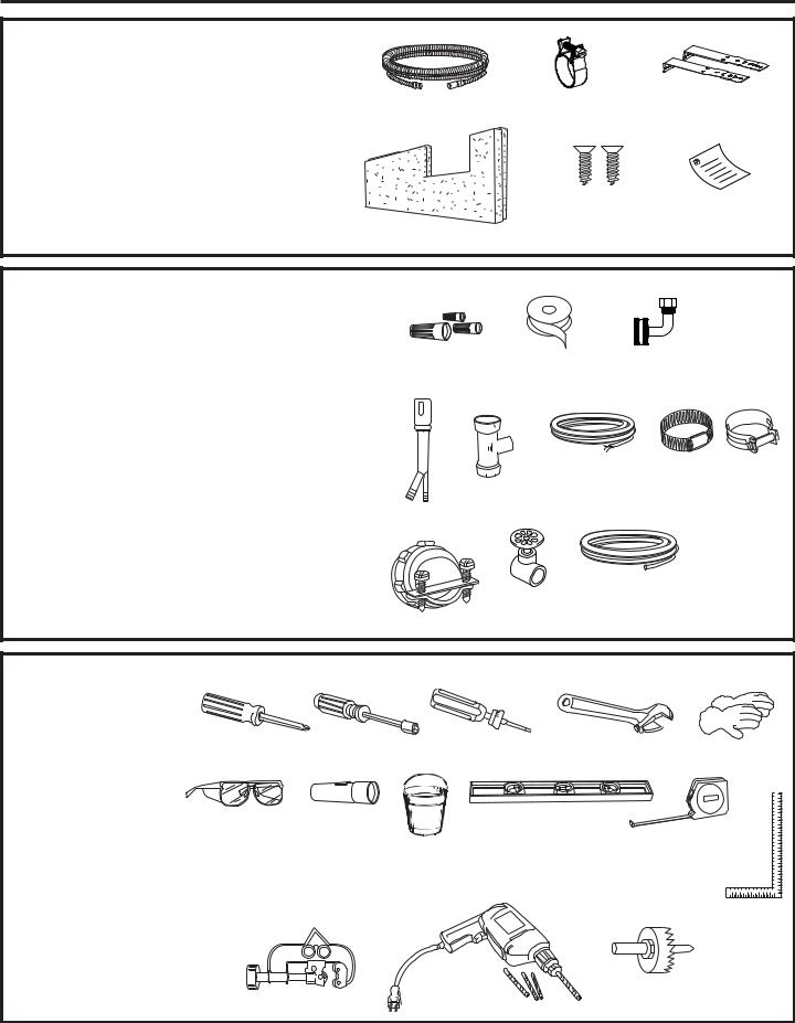
PARTS SUPPLIED IN INSTALLATION PACKAGE:
•Drain hose extension
•Hose Clamp
•2 mounting brackets for wood countertop or side cabinets
•Toekick Insulation
•6 Phillips-Head screws to secure dishwasher to underside of countertop or to side cabinets
•Literature, samples and/or coupons
|
|
|
Hose Clamp |
|
Mounting Brackets |
||
Drain Hose |
|||||||
Extension |
|
|
|
|
|
||
|
|
|
|
|
|
|
|
|
|
|
|
|
|
|
|
|
|
|
|
|
|
|
|
Phillips-Head |
Literature |
Screws |
|
Toekick Insulation
MATERIALS YOU WILL NEED:
• UL-listed wire nuts (3) |
|
|
• Thread Seal Tape |
|
|
• 90° elbow (3/4” hose internal thread on one end, opposite Wire Nuts (3) |
Thread Seal |
90° Elbow |
end sized to fit water supply) |
Tape |
|
Materials For New Installations Only:
•Air gap for drain hose, if required
•Waste tee for house plumbing, if applicable
•Electrical cable or Power Cord Kit WX09X70910 (5’ 4” long) or WX09X70911 (7’ 9” long) depending on your installation.
•Screw-type hose clamp(s)
•Strain relief for electrical connection
•Hand shut-off valve (recommended)
•Hot water line–3/8” minimum, copper tubing (including ferrule, compression nut) or Haier Appliances Part # WX28X326, flexible braided hose.
|
Electrical Cable |
Hose Clamp(s) |
|
|
(or Power Cord, if |
|
|
Waste Tee |
applicable) |
|
|
Air Gap |
|
|
|
|
Hand |
Hot Water Line, |
|
|
Ferrule and |
|
|
Strain Relief |
Shut-Off |
Compression Nut |
|
Valve |
|
|
|
TOOLS YOU WILL NEED:
•Phillips-head screwdriver
•1/4” and 5/16” nutdriver
•T25 torque driver
•6” adjustable wrench
•Gloves
•Safety glasses
•Flashlight
•Bucket to catch water when flushing the line
•Level
•Measuring tape
•Carpenter’s square
Phillips-Head |
1/4” and 5/16” |
T25 Torque |
6” Adjustable |
Gloves |
Screwdriver |
Nutdriver |
Driver |
Wrench |
|
Safety Glasses |
Flashlight |
|
Level |
Measuring Tape |
|
Bucket |
|
|
|
|
|
|
Carpenter’s |
|
|
|
|
|
|
|
|
|
|
Square |
For New Installations Only:
• Tubing cutter
• Drill and appropriate bits |
Drill and Bits |
Hole Saw Set |
• Hole saw set |
Tubing Cutter |
|
|
|
2
Installation Preparation
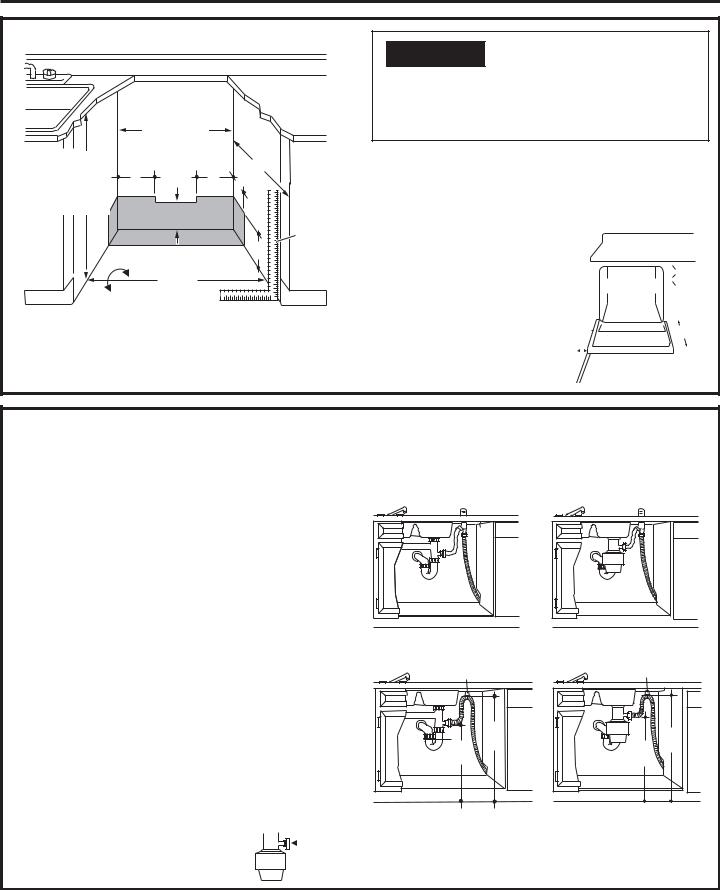
PREPAREDISHWASHERENCLOSURE
|
This wall area |
|
|
|
|
|
MUST be |
|
|
32-1/2” min. to |
|
free of |
|
|
pipes and wires |
24” |
|
||
34-3/4” max. |
5” |
5” |
|
|
Underside of |
3” |
|
||
countertop to |
|
|
|
|
floor |
|
4” |
|
Cabinets |
|
|
|
|
square |
|
Floor MUST be even |
6” |
and |
|
|
plumb |
|||
|
with room floor |
|
|
|
|
|
18” |
|
|
Plumbing and electric service |
|
|||
|
MUST enter shaded area |
|
||

 WARNING
To reduce the risk of electric shock, fire, or injury to persons, the installer must ensure that the dishwasher is completely enclosed at the time of installation.
•The dishwasher must be installed so that drain hose is no more than 12’ in length for proper drainage.
•The dishwasher must be fully enclosed on the top, sides and back, and must not support any part of the enclosure.
CLEARANCES: |
|
|
|
|
|
|
|
|
|
|
|
|
|
|
|
|
|
|
|
|
|
|
|
|
|
|
|
|
|
|
|
|
|
|
|
|
|
|
|
|
|
|
|
|
|
|
|
|
|
|
|
|
|
|
|
|
|
|
|
|
|
|
|
|
|
|
|
|
|
|
|
• When installed into a corner, |
|
|
|
|
|
|
|
|
|
|
|
|
Countertop |
|
|
||||||||
allow 2” min. clearance between |
|
|
|
|
|
|
|
|
|
|
|
|
|
|
|
|
|
|
|
|
|
|
|
dishwasher and adjacent cabinet, |
|
|
|
|
|
|
|
|
|
|
|
|
Dishwasher |
|
|
|
|
|
|
|
|
||
wall or other appliances. Allow |
|
|
|
|
|
|
|
|
|
|
|
|
|
|
|
|
|
|
|
|
|
|
|
|
|
|
|
|
|
|
|
|
|
|
|
|
|
|
|
|
|
|
|
|
|
|
|
23-1/8” min. clearance from the |
|
|
|
|
|
|
|
|
|
|
|
|
|
|
|
|
|
|
|
|
|
|
|
|
|
|
|
|
|
|
|
|
|
|
|
|
|
|
|
|
|
|
|
|
|
|
|
front of the dishwasher for door |
|
|
|
|
|
|
|
|
|
|
|
|
|
|
|
23-1/8" |
|||||||
|
|
|
|
|
|
|
|
||||||||||||||||
|
|
|
|
|
|
|
|
|
|
|
|
|
|
|
|
|
|||||||
opening. |
|
|
|
|
|
|
|
|
|
|
|
|
|
|
|
|
|
|
|
|
|
|
|
|
|
|
|
|
|
|
|
|
|
|
Clearance for Door |
||||||||||||
|
|
|
|
|
|
|
|
|
|
|
|||||||||||||
|
|
|
|
|
|
|
|
|
Opening 2” Minimum |
||||||||||||||
|
|
|
|
|
|
|
|
|
|
|
|
|
|
|
|
|
|
|
|
|
|
|
|
DRAIN REQUIREMENTS
•Follow local codes and ordinances.
•Do not exceed 12’ distance to drain.
•Drain connection height is not to exceed 72” above bottom of dishwasher.
NOTE : Air gap must be used if waste tee or disposer connection is less than 18” above floor to prevent siphoning.
DETERMINE DRAIN METHOD
The type of drain installation depends on the following questions.
•Do local codes or ordinances require an air gap?
•Is waste tee less than 18” above floor?
If the answer to either question is YES, Method 1 MUST be used.
• If the answers are NO, either method may be used.
CABINET PREPARATION
•Drill a 1-1/2” diameter hole in the cabinet wall within the shaded areas shown in PREPARE DISHWASHER
ENCLOSURE for the drain hose connection.Theholeshould besmoothwithnosharpedges.
IMPORTANT – When connecting drain line to disposer, check to be sure that drain plug has been 
removed. DISHWASHER WILL NOT DRAIN IF PLUG IS LEFT IN PLACE.
Method 1 – Air Gap with Waste Tee or Disposer
An air gap must be used when required by local codes and ordinances. The air gap must be installed according to manufacturer’s instructions.
Method2–“HighDrainLoop”withWasteTeeorDisposer
Drain Hose Hanger |
Drain Hose Hanger |
|
32" |
18" |
Min. |
Min. |
|
18" |
32" |
Min. |
|
Min. |
|
Tip: Avoid unnecessary service call charges.
Always be sure disposer drain plug has been removed before attaching dishwasher drain hose to the disposer.
3
Installation Preparation
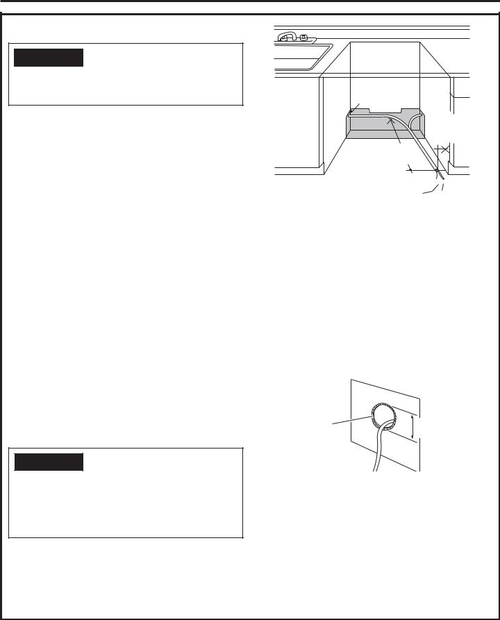
PREPARE ELECTRICAL WIRING

 WARNING
Remove all power leading to the appliance from the circuit breaker or fuse box before beginning installation. Failure to do so can result in a risk of electrical shock.
Electrical Requirements
•This appliance must be supplied with 120V, 60 Hz., and connected to an individual properly grounded branch circuit, protected by a 15or 20-ampere circuit breaker or time-delay fuse.
•Wiring must be 2 wire with ground and rated for 167°F (75°C).
•If the electrical supply does not meet the above requirements, call a licensed electrician before proceeding.
Grounding Instructions–Permanent Connection
This appliance must be connected to a grounded metal, permanent wiring system, or an equipment-grounding conductor must be run with the circuit conductors and be connected to the equipment-grounding terminal or lead on the appliance.
Grounding Instructions–Power Cord Models
This appliance must be grounded. In the event of a malfunction or breakdown, grounding will reduce the risk of electric shock by providing a path of least resistance for electric current. This appliance is equipped with a cord having an equipment-grounding conductor and
a grounding plug. The plug must be plugged into an appropriate outlet that is installed and grounded in accordance with all local codes and ordinances.

 WARNING
The improper connection of the equipment grounding conductor can result in a risk of electric shock. Check with a qualified electrician or service representative if you are in doubt that the appliance is properly grounded. Do not modify the plug provided with the appliance; if it will not fit the outlet, have a proper outlet installed by a qualified technician.
1-1/2” Dia.
Hole (Max.)
3” from Cabinet
24” from Wall
Ground


Black White
Cabinet Preparation & Wire Routing
•The wiring may enter the opening from either side, rear or the floor within the shaded area illustrated above in figure and as defined in PREPARE DISHWASHER ENCLOSURE section.
•Cut a 1-1/2" maximum diameter hole to admit the electrical cable. Edges of hole should be smooth and rounded. Permanent wiring connections may pass through the same hole as the drain hose and hot water line, if convenient. If cabinet wall is metal, the hole edge must be covered with a bushing.
NOTE: Power cords with plug must pass through a separate hole in the cabinet.
|
Metal |
Cabinet |
|
|
|
|
|
Wall |
Cord Protector |
|
Hole Diameter |
(Obtain locally |
|
1-1/2” Maximum |
as needed) |
|
|
Electrical Connection to Dishwasher
Electrical connection is on the right front of dishwasher.
• For permanent connections the cable must be routed as shown in figure. Cable must extend a minimum of 24" from the rear wall.
• For power cord connections, install a 3-prong grounding type receptacle in the sink cabinet rear wall, 6" min. or 18" maximum from the opening, 6" to 18" above the floor.
• Use only WX09X70910 (5’ 4” long) or WX09X70911
(7’ 9” long) Dishwasher Power Cord Kit. Do not use an extension cord or adapter plug with this appliance.
4
Installation Preparation
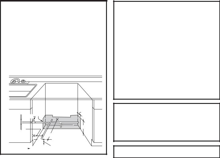
PREPARE HOT WATER LINE
NOTE: Haier Appliances recommends copper tubing for the water line, but if you choose to use flexible hose, use Haier Appliances WX28X326, flexible braided hose.
•The water supply line (3/8” copper tubing or flexible braided hose) may enter from either side, rear or floor within the shaded area shown in the figure.
•The water supply line may pass through the same hole as the electrical cable and drain hose. Or, cut an additional 1-1/2" diameter hole to accommodate the water line. If power cord with plug is used, water line must not pass through power cord hole.
|
|
1-1/2” |
|
|
|
Dia. |
3" |
|
Shut-off |
Hole |
|
|
|
||
Hot |
Valve |
|
|
|
5" |
|
6" |
|
|
|
|
|
From |
|
15" From Wall |
Cabinet |
|
||
|
|
|
|
|
|
|
|
|
3" From Floor |
|
|
|
|
|
|
|
|
|
|
Cabinet Face |
|
|
|
|
|
|
|
||
|
|
|
|
|
|
|
|
||
WATER LINE CONNECTION
•If using a flexible braided supply hose, label the hose with the installation date to use as reference. Flexible braided hoses, elbows and gaskets should be replaced in 5 years.
•Turn off the water supply.
•Install a hand shut-off valve in an accessible location, such as under the sink. (Optional, but strongly recommended and may be required by local codes.)
•Water connection is on the left side of the dishwasher. Install the hot water inlet line, using no less than 3/8” copper tubing or a flexible braided hose. Route the line as shown in PREPARE HOT WATER LINE and extend forward at least 19” from rear wall.
•Adjust water heater for 120°F to 140°F temperature.
•Flush water line to clean out debris.
•The hot water supply line pressure must be 20-120 PSI.
PREPARATION
Locate the items in the installation packages:
•Screws
•Drain hose extension
•Mounting brackets
•Literature, product samples and/or coupons
Turn page to begin dishwasher installation.
5

Dishwasher Installation
STEP 1 CHECK DOOR BALANCE

 CAUTION
Opening the door will cause the dishwasher to tip forward when it is
not fully installed. When opening the door prior to the dishwasher being fully installed, hold the top of the
dishwasher securely with one hand and hold the door with the other hand. Gloves should be worn.
To check the door balance, hold the top of the dishwasher firmly.
•Check the door balance by opening and closing the door.
• If the door drops |
|
when released, |
|
increase the |
|
spring tension. |
|
If the door rises |
Increase |
when released, |
|
decrease the |
Decrease |
spring tension. |
|
STEP 2 ADJUST LEVELING LEGS
•Move the dishwasher close to the installation location and lay it on its back. NOTE: Do not place the dishwasher on its side.
•Measure installation height and dishwasher height. Extend leveling legs out from the dishwasher base, 1/2”
less than installation height.
Adjust to |
Leveling leg |
shown with the |
|
Installation |
dishwasher laying |
Height |
on its back |
|
STEP 3 REMOVE TOEKICK
• Remove the 4 toekick screws and the 2-piece toekick. Set aside for use in Step 19.
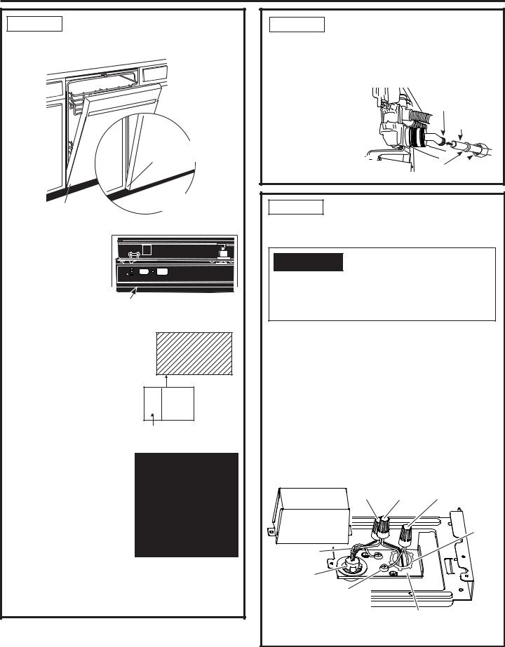
STEP 4 INSTALL POWER CORD
Skip this step if the dishwasher will be permanently connected to the house electrical system or has a factory-installed power cord.
•The power cord and connections must comply with the National Electrical Code, Section 422 and/or local codes and ordinances. Maximum power cord length is 6 feet. Power Cord Kit WX09X70910 or WX09X70911, available for purchase from an authorized
Haier Appliances dealer, meets these requirements.
Black |
UL Listed Wire Nuts |
|
White |
Ground/ |
|
|
|
Green |
Junction Box |
|
Strain |
Cover |
|
|
Dishwasher |
|
Relief on |
|
Power |
|
Ground Wire |
|
Cord |
and Screw |
|
|
Dishwasher |
|
|
Wires |
|
|
Dishwasher Ground
Wire and Screw
Junction Box Bracket
• Remove junction box cover.
•Install strain relief in the junction box bracket.
•Insert the power cord through the strain relief and tighten.
•Make sure black, white and green dishwasher wires are threaded through the hole in the junction box bracket.
•Connect power cord white (or ribbed) to dishwasher white, black (or smooth) to dishwasher black and ground to dishwasher green wire. Use UL-listed wire nuts of appropriate size.
•Replace junction box cover using the screw. Be sure wires are not pinched under the cover.
6
Dishwasher Installation
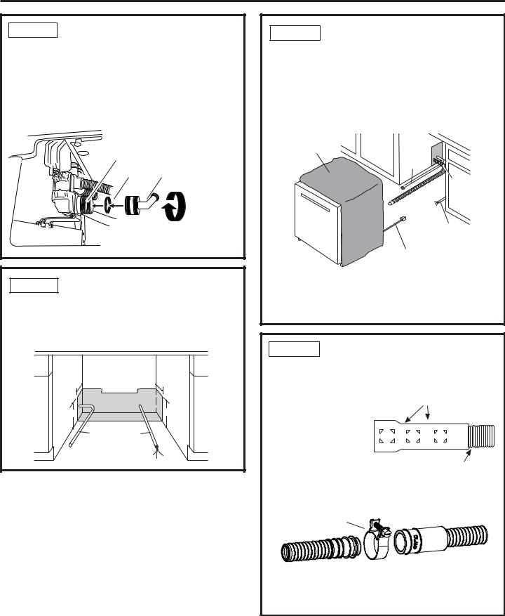
STEP 5 INSTALL 90° ELBOW
•Ensure rubber gasket is located between valve and elbow.
•Thread 90° elbow onto the water valve.
•Do not overtighten elbow. Water valve bracket could bend or water valve fitting could break.
•Position the end of the elbow to face the rear of the dishwasher.
Water
Valve
Gasket |
90° |
Screw the 90° |
Elbow |
||
|
|
elbow onto |
|
|
the water |
|
|
valve until it |
|
|
is secure and |
|
|
points to the |
|
|
rear of the |
|
|
dishwasher |
STEP 6 POSITION WATER LINE AND HOUSE WIRING
•Position water supply line and house wiring on the floor of the opening to avoid interference with base of dishwasher and components under dishwasher.
3" |
3" |
6" |
6" |
Water |
House |
Line |
Wiring |
STEP 7 INSTALL DRAIN HOSE, THROUGH CABINET
•Stand the dishwasher upright and position it in front of cabinet opening. Insert drain hose into the hole in cabinet side. If a power cord is used, guide the end through a separate cabinet opening.
Maximum
Drain Hose
Length 12’
Insulation
Blanket Water
Line
Drain
Hose
House Wiring
Power Cord
(If Used)
Tip: Prevent unnecessary service call charges for fill, drain or noise concerns.
Position utility lines so they do not interfere with anything under or behind the dishwasher.
STEP 8 CONNECT DRAIN LINE
The molded end of the drain hose will fit 5/8” through 1” diameter inlet ports on the air gap, waste tee or disposer.
• Determine size of inlet port.
• Cut drain hose |
|
Cutting Lines |
|
connector on the |
|
|
|
marked line, if |
|
|
|
required, to fit the |
1" |
3/4" |
5/8" |
inlet port. |
|
|
|
|
|
|
|
• Use the drain hose extension provided and connect directly
to the drain loop already
attached to the unit. Secure the connection, with hose clamp, to the provided user bag drain hose.
Hose Clamp
•DRAIN CONNECTION HEIGHT IS NOT TO EXCEED 72”
ABOVE BOTTOM OF DISHWASHER.
•TOTAL DRAIN HOSE LENGTH MUST NOT EXCEED 12 FEET FOR PROPER DRAIN OPERATION.
7
Dishwasher Installation
STEP 8 CONNECT DRAIN LINE (CONT.)
•Connect drain line to air gap, waste tee or disposer using the previously determined method. Secure hose with a screw-type clamp.
Method 1 – Air gap with waste tee or disposer
Waste Tee Installation |
Disposer Installation |
Method 2 – “High drain loop” with waste tee or disposer
Fasten drain hose to underside of countertop with a hanger.
Drain Hose Hanger |
Drain Hose Hanger |
|
32" |
18" |
Min. |
Min. |
|
Waste Tee Installation
18" |
32" |
Min. |
|
Min. |
|
Disposer Installation
IMPORTANT – Either one of the above methods must be used or dishwasher will not operate properly.
IMPORTANT – When connecting |
|
|
|
|
|
|
drain line to disposer, check to |
|
|
|
|
Remove |
|
|
|
|
|
|||
be sure that drain plug has been |
|
|
|
|
|
Drain |
|
|
|
|
|
||
removed. DISHWASHER WILL |
|
|
|
|
Plug |
|
NOT DRAIN IF PLUG IS LEFT IN |
|
|
|
|
|
|
|
|
|
|
|
||
PLACE. |
|
|
|
|
||
Tip: Avoid unnecessary service call charges for a no drain complaint.
Make sure excess drain hose has been pulled through the cabinet opening. This will prevent excess hose in the dishwasher cavity from becoming kinked or crushed by the dishwasher.
STEP 9 INSTALL MOUNTING
BRACKETS
You will need the mounting brackets and 4 of the PhillipsHead screws set aside in the PREPARATION section.
You must install the mounting brackets onto the dishwasher tub frame top OR sides prior to sliding the dishwasher into place under the countertop. The mounting brackets have several available attachment positions to accommodate different cabinet constructions.
TOP MOUNTING OPTION
Install mounting brackets on top if the underside of countertop is wood or wood-like material that accepts screws:
IMPORTANT - After installing brackets and before closing dishwasher door, adjust the brackets by bending them up as needed, so that they do not contact the top of dishwasher door and cause damage.
Top Mounting
Phillips |
Phillips |
Bracket |
Bracket Screws |
|
|
Screws |
|
|
Bend and break at cutout slots in brackets (if/as necessary) on both sides after installing if counter has a short overhang.
•If you are installing the dishwasher under a counter with a short overhang, the countertop brackets may extend beyond the edge of the counter. If this is the case, remove the excess length by repeatedly bending the brackets at the front notch only until they break.
8
Dishwasher Installation
STEP 9 INSTALL MOUNTING BRACKETS (CONT.)
SIDE MOUNTING OPTION
Install mounting brackets on sides if the countertop is granite or similar material that will not accept wood screws:
•Break off front portion of the tab with pliers at the location shown, prior to attaching to dishwasher.
•Position the left-hand side bracket as shown. Repeat with the right bracket.
Side Mounting
Phillips
Screws
Bracket
Bend and break at cutout slots in brackets (if/as necessary) on both sides before installing.
STEP 10 SLIDE DISHWASHER PARTIALLY INTO CABINET
IMPORTANT – Do not push against front panel with knees. Damage will occur.
•Grasp the sides of the front panel and slide dishwasher into the opening a few inches at a time.
Do not push against front
door panel with knee. Damage to the door panel will
occur.
•As you proceed, pull the drain hose through the opening under the sink. Stop pushing when the dishwasher extends about 6 inches forward of adjacent cabinets.
•Make sure drain hose is not kinked under or behind the dishwasher.
•Make certain the house wiring, drain line and water line do not interfere with components under dishwasher.
STEP 11 POSITION DISHWASHER UNDER COUNTERTOP
•Push the dishwasher into the cabinet.
•Push the sides with your hands. Do not use your knee against the door since door damage will occur.
Do not push against front
door panel with knee. Damage to the door panel will
occur.
•Check that the tub insulation blanket does not get “bunched-up” or interfere with the springs as you slide it into the cabinet.
•Center the dishwasher in the opening.
•Front of door panel should be flush with face of cabinet.
•Carefully open and close the door to ensure that the door panel does not catch or rub on the cabinet frame.
•If the door catches or rubs on the frame, reposition and/or level the unit (see Step 14) until the door moves freely and does not contact the cabinet frame.
9
Dishwasher Installation
STEP 11 POSITION DISHWASHER UNDER COUNTERTOP (CONT.)
Door
Fits and
Swings
Back
Behind
Cabinet
Frame
Correct
Alignment
The controls on these models are designed to be hidden by your countertop. Align the dishwasher as shown in figure.
Door Catches on Cabinet Frame
Incorrect
Alignment
TOP VIEW
Hold 3 Sec To Cancel
Clean
Sanitized
Start
Controls Hidden by Countertop
Leave a 1/2” minimum gap between the underside of the countertop and the top of the dishwasher door as shown in figure.
NOTE: If the drain hose gets trapped behind the unit it can prevent the controls from being hidden by the countertop.
Tip: The leveling legs can be used to increase or decrease the amount of gap between the controls and the countertop affecting the visibility of the controls.
IMPORTANT– Leave a 1/2” minimum gap between the controls and the underside of the countertop to prevent condensation and damage to the control panel from screwheads.
Counter top
1/2”
Min.  Front View
Dishwasher
Door
Countertop
Control
Panel
NOTE: If this dishwasher is replacing an existing dishwasher, the old countertop bracket screw holes may not be in the correct position to accept a top-control model. New holes may be required.
STEP 12 CONNECT WATER SUPPLY
Connect water supply line to 90° elbow.
If using a flexible braided hose connection:
• Attach nut to 90° elbow using an adjustable wrench.
If using a copper tubing connection:
• Slide compression
nut, then ferrule over end of water line.
• Insert water line into 90° elbow.
• Slide ferrule against elbow and secure 


 with compression nut.
90° Elbow
Hot Water
Supply Line
Ferrule Compression
Nut
STEP 13 CONNECT POWER SUPPLY
If a power cord with plug is already installed proceed to Step 14.

 WARNING
If house wiring is not 2-wire with ground, a ground must be provided by the installer. When house wiring is aluminum, be sure to use UL-Listed anti-oxidant compound and aluminum-to-copper connectors.
•Remove junction box cover.
•Secure house wiring to the back of the junction box with a strain relief.
•Locate the 3 dishwasher wires, (white, black and green) with the stripped ends coming out of the AC jumper. Use UL listed wire nuts of appropriate size to connect incoming ground to green, white to white and black to black.
•Replace the junction box cover using the screw. Check to be sure that wires are not pinched under the cover.
•If using a Power Cord Kit, use Haier Appliances part number WX09X70910 or WX09X70911 and refer to the included instructions.
NOTE: Do not remove the Junction Box Bracket.
Black |
UL Listed Wire Nuts |
|
White |
Ground/ |
|
|
|
Green |
Junction Box |
|
House |
Cover |
|
|
|
|
Wiring |
Dishwasher |
|
with |
|
Strain |
|
Ground Wire |
|
Relief |
and Screw |
|
|
Dishwasher |
|
|
Wires |
|
|
Dishwasher Ground |
|
|
Wire and Screw |
|
|
Junction Box Bracket
NOTE: All ground screws, brackets and wires must remain intact.
10
Dishwasher Installation
STEP 14 LEVEL DISHWASHER
IMPORTANT – Dishwasher must be level for proper dish rack operation, wash performance and door operation. The dishwasher must be leveled left to right and front to back.
•Make sure 1/2” minimum gap under the countertop is maintained.
•Remove the lower dish rack and place a level on the door and lower rack track as shown in the figure.
Use Level to Check |
Use Level to Check |
Front-to-Back |
Side-to-Side |
•If the dishwasher is not level, adjust the four leveling legs individually.
Tip: Prevent unnecessary
service charges. Verify dishwasher is leveled.
Pull the dish racks half way out. They should stay put. Open and close the door. The door should fit in the tub opening without hitting the
side of the tub. If the racks roll on their own, or the door
hits the side of tub, re-level the dishwasher.
IMPORTANT – After leveling, verify that the dishwasher is still in the correct position shown in Step 11.
STEP 15 SECURE DISHWASHER TO COUNTERTOP OR CABINET
In this step you will need the 2 remaining Phillips Head screws from the screws set aside in the PREPARATION section.
The dishwasher must be secured to the countertop or the cabinet sides.
Countertop Mounting


 Side
Side
 Mounting
When the underside of the
countertop is wood, use Method 1 (Countertop Mounting).
Use Method 2 (Side Mounting) when the underside of the countertop is made of a material, such as granite, that will not accept wood screws.
STEP 15 SECURE DISHWASHER TO COUNTERTOP OR CABINET
·ÌØ×Ý ¸
IMPORTANT – Prevent door panel and control
panel damage. Dishwasher must be positioned so the front panel and control panel do not contact the adjacent cabinets or countertop. Mounting screws must be driven straight and flush. Protruding screw heads could scratch the door panel or control panel and interfere with door operation.
Method 1
Secure dishwasher to underside of wood countertop.
•Fasten the dishwasher to the underside of the countertop with the 2 Phillips-Head screws. Refer to figure. Make certain screws are driven straight and flush to prevent panel damage.
Wood Countertop
Screws into Upper Brackets
Method 2
Secure dishwasher to cabinet sides.
•Remove plug buttons from tub. Do not discard.
•Fasten the dishwasher to the adjacent cabinets with the 2 Phillips-Head screws provided. Refer to the figure. Make certain screws are driven straight and flush to prevent panel damage. Do not screw into the cabinet face frame.
•Re-install plug buttons.
Solid Surface Countertop
Plug Buttons
Screws into Side Brackets
•Re-check that the dishwasher is square and level at both the top and bottom of the cabinet opening, with no twisting or distortion of the tub or door after mounting to the cabinets/countertop. Adjust if necessary.
•Confirm all leveling legs are in contact with the floor
to prevent the dishwasher from rocking and ensure proper door and latch operation.
Both Methods
|
|
|
Countertop |
|
|
|
|
|
|
1/2" |
|
|
Dishwasher Door |
|
|
||||
Min. |
|
|
|
|
|
|
|
|
|
•When step is complete, close dishwasher door and verify that gap between countertop and top of dishwasher door is at least 1/2”.
11
 Loading...