


|
|
Room Air Conditioner |
|
|
|
Climatiseur individuel |
|
|
|
Aire acondicionado |
|
|
|
de uso doméstico |
|
User & Care Guide |
|
ESA415M |
|
Guide d'utilisation et d'entretien |
|
||
|
ESA418M |
||
|
|
|
|
Guía de uso y cuidado |
|
ESA424K |
|
|
|
|
|
|
|
|
|
|
|
|
|
|
|
|
Design may vary by model number. |
|
Laconfigurationpeutvarierselonle |
|
|
Eldiseñopuedevariarconformeal |
|||||
|
|
|
||||||||
|
|
|
|
|
numéro de modèle. |
|
|
número de modelo |
||
Thisusermanualistobeonlyusefor |
|
Ceguided'utilisationdoitêtre |
|
|
Estemanualdelusuariosólosedebe |
|||||
|
|
|
||||||||
|
|
|
||||||||
electroniccontrol14,500BTU,18,000 |
|
utiliséstrictementaveclesmodèlesà |
|
|
utilizarparaelcontrolelectrónico |
|||||
BTUand24,000BTU-Somemodels |
|
commandeélectroniquede14500BTU, |
|
|
14,500BTU,18,000BTUy24,000BTU– |
|||||
mayhaveanadditionalletterafterthe |
|
18000BTUet24000BTU-Sur |
|
|
Algunosmodelospuedentener |
|||||
model number. |
|
certainsmodèles,lenumérodemodèle |
|
|
unaletraadicionaldespués |
|||||
|
|
|
|
|
peutêtresuivid'unelettre. |
|
|
delnúmerodemodelo. |
||
|
|
|
|
|
|
|
||||

ENGLISH
PRODUCT REGISTRATION
Thank you for purchasing our Haier product. This easy-to-use manual will guide you in getting the best use of your product.
Remember to record the model and serial numbers. They are on a label on the side of your unit.
Model number
Serial number
Date of purchase
Staple your receipt to your manual. You will need it to obtain warranty service.

TABLE OF CONTENTS |
|
SAFETY INFORMATION............................................................................................................. |
2 |
Important Safety Precautions................................................................................................ |
2-3 |
Operational Safety & Warnings................................................................................................... |
4 |
INSTALLATION REQUIREMENTS.............................................................................................. |
5 |
Tools and Parts............................................................................................................................. |
5 |
Location Requirements............................................................................................................... |
6 |
Electrical Requirements........................................................................................................ |
7-10 |
HOW TO INSTALL..................................................................................................................... |
11 |
Unpacking the Air Conditioner................................................................................................. |
11 |
Preparing the Air Conditioner: ESA415 / ESA418............................................................. |
11-13 |
Preparing the Window: ESA415 / ESA418................................................................................ |
14 |
Completing the Installation: ESA415 / ESA418....................................................................... |
15 |
Preparing the Air Conditioner: ESA424.............................................................................. |
16-17 |
Preparing the Window: ESA424................................................................................................ |
18 |
Completing the Installation: ESA424....................................................................................... |
19 |
Completing the Installation...................................................................................................... |
20 |
USING YOUR AIR CONDITIONER............................................................................................ |
21 |
Starting the Air Conditioner................................................................................................ |
21-24 |
Using the Remote Control.................................................................................................. |
25-27 |
Changing the Air Direction........................................................................................................ |
27 |
Normal Sounds of an Air Conditioner....................................................................................... |
28 |
CARING FOR YOUR AIR CONDITIONER................................................................................. |
29 |
Cleaning the Air Filter................................................................................................................ |
29 |
Cleaning the Front Panel........................................................................................................... |
30 |
Annual Maintenance.................................................................................................................. |
30 |
Customer Service...................................................................................................................... |
30 |
TROUBLESHOOTING............................................................................................................... |
31 |
LIMITED WARRANTY............................................................................................................... |
32 |
ENGLISH
ENGLISH
IMPORTANT SAFETY PRECAUTIONS
WARNING
THE INFORMATION IN THIS USE & CARE GUIDE MUST BE FOLLOWED TO MINIMIZE THE RISK OF PERSONAL INJURY, FIRE, ELECTRIC SHOCK OR OTHER UNSAFE CONDITIONS.
THE INSTRUCTIONS IN THIS USE & CARE GUIDE ARE NOT MEANT TO INCLUDE EVERY POSSIBLE CONDITION OR SITUATION THAT
MAY OCCUR. USE CAUTION AND CARE WHEN INSTALLING, OPERATING
AND CLEANING THE AIR CONDITIONER.
1.Use this air conditioner only for its intended application as described in this Use & Care Guide.
2.This air conditioner must be properly installed and use the correct wall outlet that matches with the air conditioner’s power supply cord in accordance with the Installation Section of this Use & Care Guide before it is operated.
3.Never unplug the air conditioner by pulling on the power supply cord. Always grip the plug firmly and pull straight out from the wall outlet.
4.Replace the power supply cord immediately if it becomes damaged in any way. A new power supply cord must be purchased from the air conditioner manufacturer and installed by a qualified technician. DO NOT use a power supply cord that is cracked, split, cut, or damaged anywhere along its length or either at the plug end or connector end.
5.Turn off the air conditioner and unplug it from the wall outlet before performing any cleaning or maintenance.
6.Do not store or use combustible or flammable materials or liquids on or near the air conditioner.
7.If the wall outlet configuration does not match the plug configuration on the air conditioner, the wall outlet must be changed by a qualified electrician.
PAGE 2 |
SAFETY INFORMATION |

IMPORTANT SAFETY PRECAUTIONS
8.This air conditioner contains R410a refrigerant and requires certified technicians to use the proper equipment, tools and safety standards that are approved for this refrigerant. Use only equipment certified for R410a refrigerant. In addition, under federal law, all refrigerant must be properly removed from the air conditioner prior to its disposal.
READ AND FOLLOW THE
SAFETY INSTRUCTIONS CAREFULLY.
SAVE THESE INSTRUCTIONS
ENGLISH
SAFETY INFORMATION |
PAGE 3 |

ENGLISH
OPERATIONAL SAFETY & WARNINGS
1.This air conditioner contains no consumer serviceable parts. If you have problems or questions regarding the operation of your air conditioner always call Haier Customer Service: 1-877-337-3639.
2.Be sure that the air conditioner is properly and securely installed in the window according to the installation instructions included in this Use & Care Guide.
3.DO NOT drill any holes in the base or sides of the air conditioner.
4.DO NOT place fingers or objects in the air discharge or air intake in the front of the air conditioner.
5.DO NOT operate the air conditioner with a protective cover on the outside section.
6.DO NOT block the air discharge or air intake areas on the front panel.
7.DO NOT block the side louvers on the outside of the air conditioner.
8.DO NOT place any objects either on the indoor or outdoor sections of the air conditioner
9.Operate the air conditioner with the air filter installed.
10.Keep this Use & Care Guide, carton and packing material for future use in removing, storing and reinstalling the air conditioner.
PAGE 4 |
SAFETY INFORMATION |
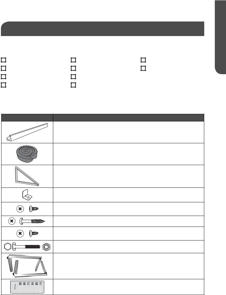
TOOLS AND PARTS
Read and follow the instructions provided with any tools listed here.
TOOLS NEEDED
Phillips head screwdriver |
Socket wrench & sockets |
Pliers |
Flat-blade screwdriver |
Tape measure |
Adjustable wrench |
Scissors |
Cordless drill and 1/8” bit |
|
Level |
Pencil |
|
PARTS SUPPLIED:
Check that all parts for your specific air conditioner are included in the parts package. NOTE: If parts are missing, call Haier Customer Service: 1-877-337-3639.
IMAGE
TEMP/TIME |
TEMP/TIME |
TIMER |
SPEED |
MODE |
ON/OFF |
PART |
14,500 BTU, 18,000 BTU |
24,000 BTU |
|
Top channel |
1 |
1 |
|
Foam seal |
1 |
1 |
|
Installation |
2 |
2 |
|
brackets |
|||
|
|
||
Window lock |
1 |
1 |
|
bracket |
|||
|
|
||
7/16" self- |
12 |
10 |
|
tapping screws |
|||
|
|
||
1" wood screws |
8 |
10 |
|
7/16" bracket |
6 |
6 |
|
screws |
|||
|
|
||
2-1/2" bolt and |
2 |
2 |
|
lock nut |
|||
|
|
||
Side curtain |
2 |
2 |
|
assembly |
|||
|
|
||
Remote control |
1 |
1 |
|
|
|
|
ENGLISH
INSTALLATION REQUIREMENTS |
PAGE 5 |

ENGLISH
LOCATION REQUIREMENTS
IMPORTANT: Observe all governing codes and ordinances. Check the location where the air conditioner will be installed. Make sure you have everything necessary for correct installation.
The site of installation should provide:
•Agroundedelectricaloutletwithin4ft.(122cm)ofwherethepowercordexitstheair conditioner.
NOTE: Donotuseanextensioncord,plugadapter,surgeprotectorormulti-outletadapter.
•Freemovementofairintheroomtobecooled.
•Alargeenoughopeningfortheairconditioner.
•Unitmustnotbeinstalledinathrough-the-wallsleeve.
NOTE: The outside cabinet louvers must not be obstructed by bushes, trees, etc. Air must be able to pass freely through the cabinet louvers.
WINDOW INSTALLATION
Models
ESA415M ESA418M
28-3/8”minimumto38”maximumopeningwidth
17-3/8” minimum opening height
Model ESA424K
31-1/4”minimumto40”maximumopeningwidth
20-1/4” minimum opening height
WARNING
•Electricalshockhazard
•Plugintoamating,grounded3prongoutlet.
•Donotremovethegroundprongfromthepowersupplycord.
•Donotuseaplugadapter,extensioncord,surgeprotector,ormulti-outletadapter
•Failuretofollowtheseinstructionscanresultininjury,fire,orelectricalshock.
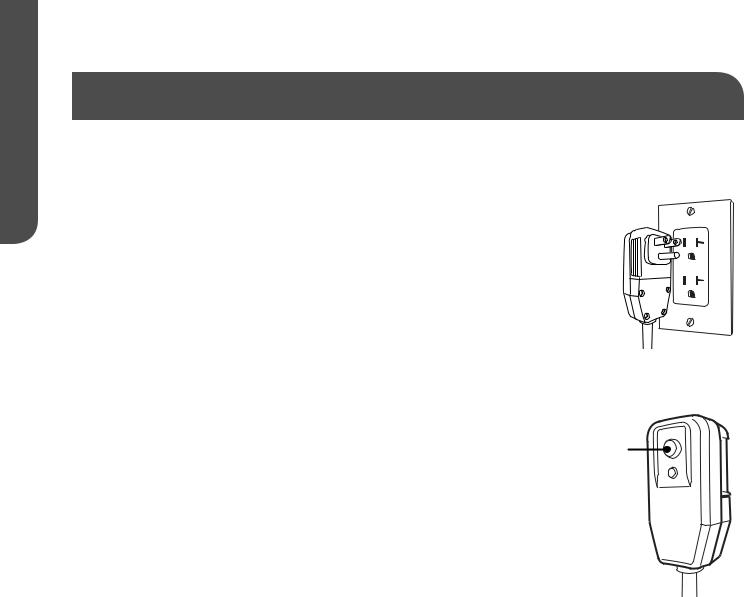
To test your power supply cord:
1.Plug power supply cord into a mating, grounded 3 prong outlet.
2.PressRESET(onsomedevices,agreenlightwillturnon).
PAGE 6 |
INSTALLATION REQUIREMENTS |
ELECTRICAL REQUIREMENTS
WARNING
ELECTRICAL SAFETY and WARNINGS
1.DO NOT cut or remove the grounding prong on the attached power supply cord. Doing so may cause sparks or fire, and voids all warranties. For safety purposes the air conditioner must be properly grounded.
2.To avoid a fire hazard or possible electric shock, DO NOT use an adapter plug, extension cord, surge protectors, or multi-outlet adapters with the air conditioner.
3.The power supply cord is equipped with a 3-prong plug which mates with the grounded 3-prong wall outlet to minimize the possibility of electrical shock from this air conditioner.
4.The power supply cord includes a leakage current detection interrupter device (LCDI). A
RESET and TEST button are on the plug case. The device should be tested on a periodic basis by pressing the TEST button and then the RESET button while it is plugged into the wall outlet. If the TEST button does not trip or the RESET will not stay engaged, do not use the air conditioner and contact a qualified service technician.
5.Have the wall outlet and circuit inspected by a qualified electrician to ensure that the wall outlet is properly grounded.
6.If there is a 2-prong wall outlet present and not a 3-prong wall outlet, it is the responsibility of the user to have it replaced with a properly grounded 3-prong outlet.
7.The air conditioner should always be plugged into a dedicated electrical outlet which has a voltage rating that matches the serial label on the side of the air conditioner.
8.The electrical ratings for your air conditioner are listed on the Model/Serial Number label. The Model/Serial Number label is located on the side of the air conditioner cabinet, or behind the front grille.
9.Specific electrical requirements are listed in the chart below. Follow the requirements for the type of plug on the power supply cord.
ENGLISH
INSTALLATION REQUIREMENTS |
PAGE 7 |
ENGLISH
ELECTRICAL REQUIREMENTS cont.
POWER SUPPLY CORD (SeeFig.1)
Wiring Requirements
For model ESA415M
•115-volt (103.5 minimum to 126.5 maximum)
•15-amp time-delay grounded fuse or circuit breaker
•Use on single outlet circuit only.
Fig. 1
ESA415M
115V
15 Amp
For model ESA418M
•230/208 volt (187 min. to 253 max.)
•15-amp time-delay fuse or circuit breaker
•Use on single outlet circuit only.
For model ESA424K
•230/208 volt (187 minimum to 253 maximum)
•20-amp time-delay grounded fuse or circuit breaker
•Use on single outlet circuit only.
RECOMMENDED GROUNDING METHOD (SeeFig.1)
ESA418M
230V
15 Amp
ESA424K
230V
20 Amp
This air conditioner must be grounded. This air conditioner is equipped with a power supply cord that has a 3 prong grounding plug. The power supply cord must be plugged into a mating, grounded 3 prong outlet, and grounded in accordance with all local codes and ordinances. If a mating outlet is not available, it is the customer’s responsibility to contact a qualified electrician and ensure that a properly grounded 3 prong outlet is installed.
|
Fig. 2 A |
RESET |
|
POWER SUPPLY CORD (SeeFig.2) |
TEST |
||
NOTE: Your air conditioner's plug may differ slightly in appearance |
B |
|
|
|
|
||
from the one shown.
A.Reset button
B.Test button
This room air conditioner is equipped with an a leakage current detection interrupter (LCDI) power supply cord required by UL. This power supply cord contains a current detection device. If the power supply cord is crushed, this device will detect current leakage and power will be disconnected from the air conditioner. If this power supply cord is damaged, it cannot be repaired and must be replaced with a cord from the product manufacturer. If the power supply cord is damaged call Haier Customer Service: 1-877-337-3639.
PAGE 8 |
INSTALLATION REQUIREMENTS |
ELECTRICAL REQUIREMENTS cont.
WARNING
• Electrical shock hazard |
|
• Do not use a plug adapter, extension cord, |
|
||
• Plug into a mating, grounded 3 prong |
|
|
|
surge protector, or multi-outlet adapter |
|
outlet. |
|
|
|
• Failure to follow these instructions can |
|
• Do not remove the ground prong from the |
|
|
|
result in injury, fire, or electrical shock. |
|
power supply cord. |
|
|
|
|
IMPORTANT: Observe all governing codes and ordinances. Check the location where the air conditioner will be installed. Make sure you have everything necessary for correct installation.
THE LOCATION SHOULD PROVIDE:
•A grounded electrical outlet within 4 ft. (122 cm) of where the power supply cord exits the air conditioner, for models:
ESA415M |
ESA418M |
ESA424K |
NOTE: Do not use an extension cord, plug adapter, surge protector or multi-outlet adapter.
•Free movement of air in the room to be cooled.
•A large enough opening for the air conditioner.
•The air conditioner must not be installed in a through-the-wall sleeve. It can only be installed in a double-hung window or in a wall. .
NOTE: The outside cabinet louvers must not be obstructed by bushes, trees, etc. Air must be able to pass freely through the cabinet louvers.
ENGLISH
INSTALLATION REQUIREMENTS |
PAGE 9 |
ENGLISH
ELECTRICAL REQUIREMENTS cont.
TO TEST YOUR POWER SUPPLY CORD:
1.Plug power supply cord into a mating, grounded 3 prong outlet.
(SeeFig.3)
Fig. 3
2. Press RESET (on some devices, a green light will turn on).
3. Press TEST (listen for click; Reset button will trip, and on some devices, a green light will turn off).
4. Press and release RESET (listen for click; Reset button will latch, and on some devices, a green light will turn on). The power supply cord is ready for operation.
NOTE:
• The RESET button must be pushed in completely for proper operation. (SeeFig.4)
• The power supply cord must be replaced if it fails to trip when the test
button is pressed or fails to reset. |
RESET |
|
|
• DO NOT turn the air conditioner on or off by unplugging the power |
Fig. 4 |
TEST |
|
supply cord from the outlet. Always turn the air conditioner on or off at |
|
the control panel or by using the remote control. |
|
• A damaged power supply cord must be replaced with a new power |
|
supply cord obtained from the product manufacturer and installed my |
|
a qualified service professional. It cannot be purchased at a retail store |
|
and must not be repaired by the user. |
|
If the power supply cord is damaged please call Haier Customer Service: 1-877-337-3639.
•The power supply cord contains no user-serviceable parts.
•Opening the tamper-resistant case voids all manufacturer warranties.
PAGE 10 |
INSTALLATION REQUIREMENTS |
UNPACKING THE AIR CONDITIONER
WARNING
EXCESSIVE WEIGHT HAZARD
When moving or lifting the air conditioner, use two or more people. Wear gloves when handling the air conditioner to protect against possible sharp edges and metal fins.
REMOVE PACKAGING MATERIALS
•Remove packaging materials. Save the carton and the foam packaging for storing the unit when not in use.
NOTE: There are NO internal packing materials to remove—Do Not open the cabinet.
•Handle the air conditioner gently.
•Keep the air conditioner upright and level. Do not set the air conditioner on its side, front, back or upside down.
•The air conditioner must be standing upright for 2 hours prior to installation and operation.
PREPARING THE AIR CONDITIONER
Unpack unit in the floor near the installation location
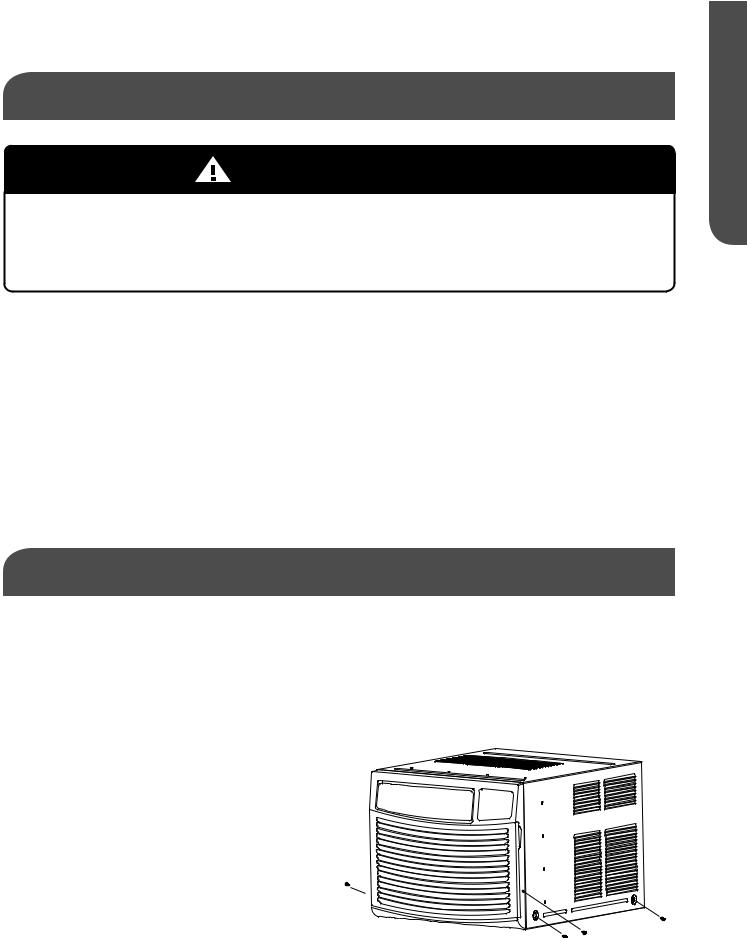
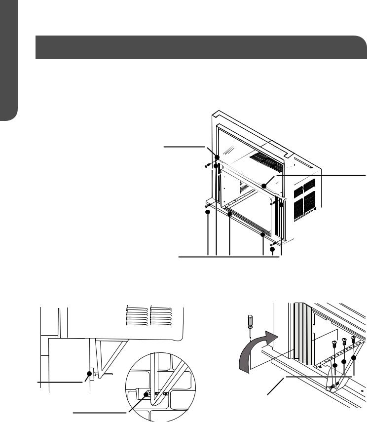
1.Removethetwofrontattachmentscrews(A). Keepthesescrewsforlateruse. Separatethe cabinet from the front panel. (SeeFig.5)
2.Removethetwoscrewsperside(B)foundatthebottomoftheoutercabinet.Usingthe basepan handle, slowly and evenly pull out the chassis from the cabinet. Use two or more people to move the air conditioner.
CAUTION:Neverexposeplasticfrontor |
Fig. 5 |
grilletoextremetemperatures. |
|
B
B A B
ENGLISH
HOW TO INSTALL |
PAGE 11 |
ENGLISH
PREPARING THE AIR CONDITIONER cont.: ESA415 / ESA418
Assemble and install side curtains and top channel (SeeFig.7)
FOR MODELS: |
ESA415M ESA418M |
7/16" Self Tapping Screws
Fig. 6
Top Channel

 Front
Front
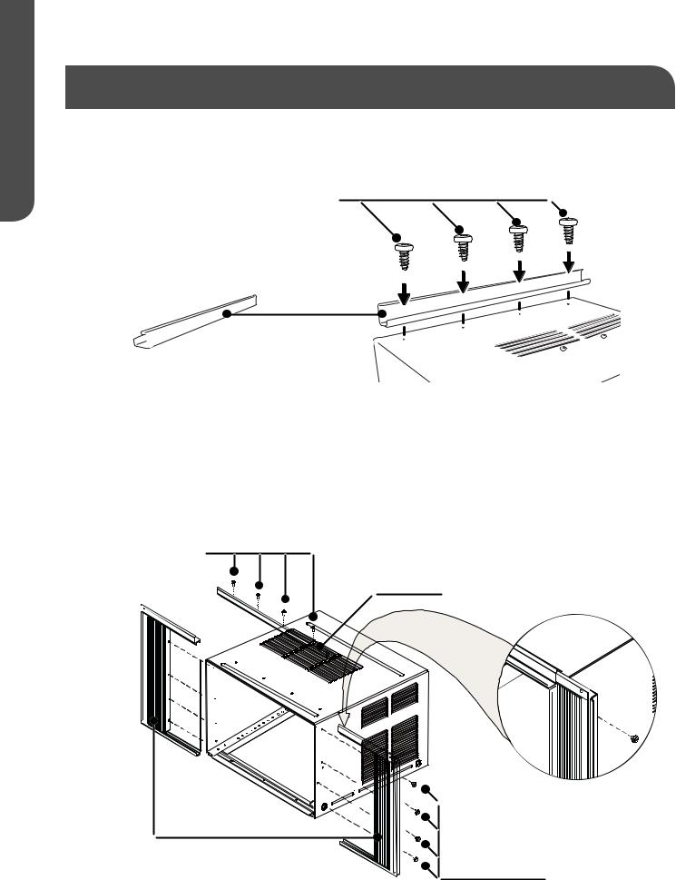
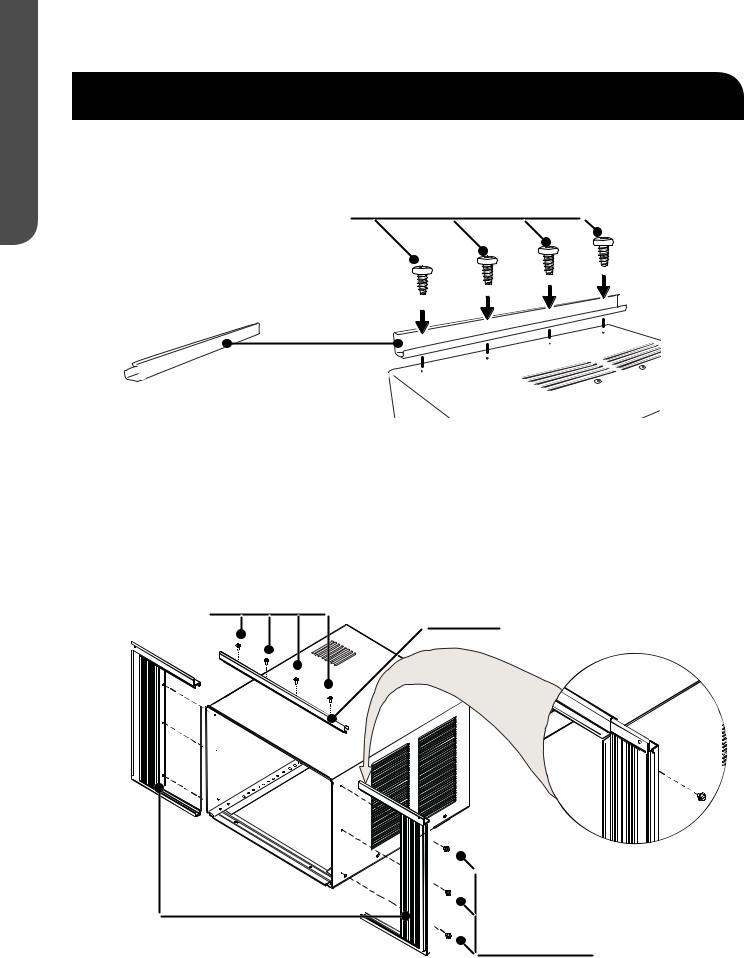
1.Installthetopchannelwithfour(4)7/16”self-tappingscrews.(SeeFig.6)
2.Slide left-hand curtain assembly into left side of top and bottom channels. Repeat for righthand curtain assembly. (SeeFig.7)
3.Fastencurtainretainerstripstothesidesofthecabinetwitheight(8)7/16”self-tapping screws.(4)Selftappingscrewsoneachside.
Fig. 7 |
7/16" Self |
Tapping Screws |
Top Channel
Side Curtains |
7/16" Self
Tapping Screws
PAGE 12 |
HOW TO INSTALL |
PREPARING THE AIR CONDITIONER cont.: ESA415 / ESA418
1.Measure the width of the window opening. (SeeFig.8)
2.Mark the center line on the inside of the windowsill with a pencil. (SeeFig.9)
WIDTH OF |
|
|
|
|
|
CENTER LINE |
|
|
|
|
|
|
|
|
|
|
|
|
|
|
|
||
|
|
|
|
|
|
|
|
|
|
||
|
|
|
|
|
|
|
|
|
|
||
|
|
|
|
|
|
|
|
|
|
||
WINDOW OPENING |
|
|
|
|
|
|
|
|
|
|
|
|
|
|
|
|
|
|
|
|
|
|
|
Fig. 8 |
|
|
|
|
|
Fig. 9 |
|
|
|
|
|
|
|
|
|
|
|
|
|
|
|
|
|
 WIDTH
WIDTH 
 CENTER
NOTES AND WARNINGS:
•Besureyourairconditionerdoesnotfalloutoftheopeningduringinstallationorremoval.
•Agroundedelectricaloutletmustbewithin4ft.(122cm)ofwherethepowersupplycord exitstheairconditioner.
•Donotblocktheairdischargeorairintakeareasonthefrontpanel.
•Donotblockthelouversontheoutsideoftheairconditioner.
INSTALL THE CABINET IN THE WINDOW (SeeFig.10)
FOR MODELS: |
ESA415M ESA418M |
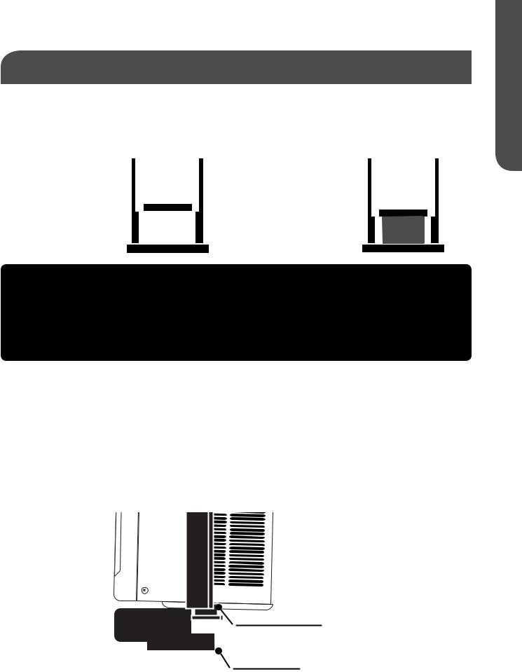
1.Center the cabinet in the windowsill. Make sure to place the cabinet so that it is resting on the windowsill with a ¼" to ½" downward tilt towards the outside (SeeFig.10). Lower the window sash behind the front flange of the top channel to hold the unit in place. The bottom channel must rest behind the window sill.
NOTE: The appearance of your model may differ from the one shown.
Fig. 10
Bottom Channel
Window Sill
ENGLISH
HOW TO INSTALL |
PAGE 13 |
ENGLISH
PREPARING THE WINDOW: ESA415 / ESA418
2.Expandbothcurtainssotheycontactthesidewindowframe. Installfour(4)1”woodscrews, two(2)intheuppercornersofthecurtainsandtwo(2)inthelowercornersofthecurtain.(See Fig.11)
3.Usethree(3)1”woodscrewstosecurethecabinet,1tothewindowsash,2tothewindowsill.
(SeeFig.11)
4.Install 2-1/2” leveling bolts to the
left and right brackets. (SeeFig.12) Window Sash
5.Secure cabinet to left and right
bracketsusingsix(6)7/16”bracket screws. 3 on each side. (SeeFig.13)
6. Adjust 2-1/2" leveling bolts to proper length and use nut lock to secure bolt. Use a wood block
between the leveling bolts and the wall if required.
1" Wood
Screws
Fig. 12
Wood Block
2-1/2 Bolt and
Nut Lock
Fig. 13
7/16" Self
Tapping Screws
Fig. 11
Top Channel
PAGE 14 |
HOW TO INSTALL |
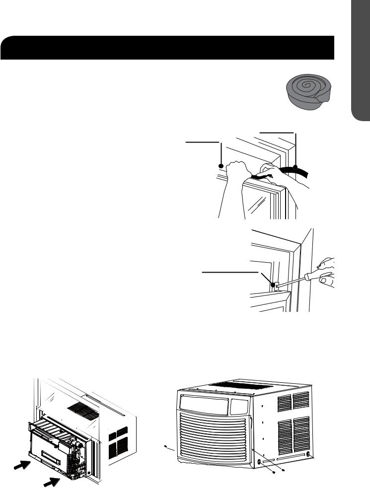
COMPLETING THE INSTALLATION: ESA415 / ESA418
COMPLETE THE INSTALLATION
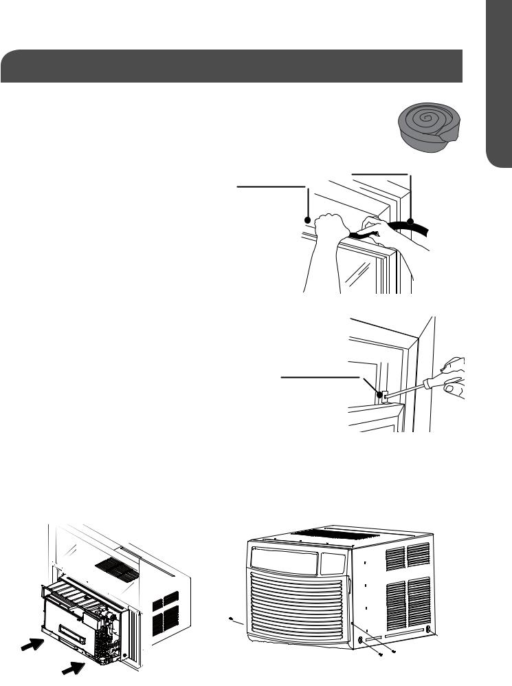
1.Uncoil the included foam seal. (SeeFig.14)
2.Insert the foam seal behind the top of the lower window sash and against the glass of the upper window. (SeeFig.15)
A.Top of lower window sash
B.Foam seal
3.Place the window lock bracket as shown. Use a1⁄8”drillbittodrillastarterholethroughthe hole in the window lock bracket and into the upper window sash. (SeeFig.16)
4.Attach the window lock bracket to the upper windowwithone(1)1”woodscrewtosecure the window in place. (SeeFig.16)
(A)Topoflower window sash
Fig. 14
(B)Foamseal
Fig. 15
INSTALLING THE CHASSIS TO THE CABINET (SeeFig.17)
When moving or lifting the air conditioner chassis, use two or more people. Wear gloves when handling the air conditioner to protect against possible sharp edges and metal fins.
1.Pick up the chassis carefully and evenly.
2.Slide the chassis into the cabinet. (SeeFig.17)
3.Reinstall the front panel.
4.Secure the front panel to the chassis using the screws removedatthestartoftheinstallation.(A)(SeeFig.18)
Fig. 16
Window Lock 
Bracket
5.Reinstalltwoofthescrewsremovedfromthecabinetatthestartoftheinstallation.(B)(See Fig.18)
6.Plug the unit in. Press RESET on the power supply cord. A green light will come on. See “Electrical Requirements."
Fig. 17 |
Fig. 18 |
|
|
B
B A
ENGLISH
HOW TO INSTALL |
PAGE 15 |
ENGLISH
PREPARING THE AIR CONDITIONER: ESA424
Assemble and install side curtains and top channel (SeeFig.19)
FOR MODEL: ESA424
7/16" Self Tapping Screws
Fig. 19
Top Channel

 Front
Front
1.Installthetopchannelwithfour(4)7/16”self-tappingscrews.(SeeFig.19)
2.Slide left-hand curtain assembly into left side of top and bottom channels. Repeat for righthand curtain assembly. (SeeFig.20)
3.Fastencurtainretainerstripstothesidesofthecabinetwithsix(6)7/16”self-tappingscrews.
(3)Selftappingscrewsoneachside.(SeeFig.20)
Fig. 20 |
7/16" Self |
|
Tapping Screws |
||
|
Top Channel
Side Curtains
7/16" Self
Tapping Screws
PAGE 16 |
HOW TO INSTALL |
PREPARING THE AIR CONDITIONER: ESA424
1.Measure the width of the window opening. (SeeFig.21)
2.Mark the center line on the inside of the windowsill with a pencil. (SeeFig.22)
WIDTH OF |
|
|
|
|
|
CENTER LINE |
|
|
|
|
|
|
|
|
|
|
|
|
|
|
|
||
|
|
|
|
|
|
|
|
|
|
||
|
|
|
|
|
|
|
|
|
|
||
|
|
|
|
|
|
|
|
|
|
||
WINDOW OPENING |
|
|
|
|
|
|
|
|
|
|
|
|
|
|
|
|
|
|
|
|
|
|
|
Fig. 21 |
|
|
|
|
|
Fig. 22 |
|
|
|
|
|
|
|
|
|
|
|
|
|
|
|
|
|
 WIDTH
WIDTH 
 CENTER
NOTES AND WARNINGS:
•Besureyourairconditionerdoesnotfalloutoftheopeningduringinstallationorremoval.
•Agroundedelectricaloutletwithin4ft.(122cm)ofwherethepowersupplycordexitstheair conditioner.
•Donotblocktheairdischargeorairintakeareasonthefrontpanel.
•Donotblockthelouversontheoutsideoftheairconditioner.
INSTALL THE CABINET IN THE WINDOW
FOR MODEL ESA424K (SeeFig.23)
1.Center the cabinet in the windowsill. Make sure to place the unit so that it is resting on the windowsill with a ¼" to ½" downward tilt towards the outside. Lower the window sash behind the front flange of the top channel to hold the unit in place. The bottom channel must rest behind the window sill. (SeeFig.23)
NOTE: The appearance of your model may differ from the one shown.
Fig. 23
Bottom Channel
Window Sill
ENGLISH
HOW TO INSTALL |
PAGE 17 |
ENGLISH
PREPARING THE WINDOW: ESA424
2.Expandbothcurtainssotheycontactthewindowframe. Installfour(4)1”woodscrews,two(2) intheupperrightcornersofthecurtainsandtwo(2)intheupperleftcornersofthecurtain.(See
Fig.24)
3.Usethree(3)1”woodscrewsinthetop mounting channel.
4.Usetwo(2)1"woodscrewstofixthecaseto window sash.
5.Install 2-1/2” leveling bolts to the left and right brackets. (SeeFig.26)Secure cabinet to left and rightbracketsusingsix(6)7/16”self-tapping screws. 3 on each side.
6.Adjust 2-1/2" leveling bolts to the proper length and use nut lock to secure bolt. Use a wood block between the leveling bolts and the wall if required. (SeeFig.26)
1" Wood |
Fig. 24 |
Screws |
|
(2)1"Wood
Screws
Fig. 25 |
Fig. 26 |
|
Wood Block
2-1/2 Bolt and
Nut Lock 7/16" Self
Tapping Screws
PAGE 18 |
HOW TO INSTALL |
COMPLETING THE INSTALLATION: ESA424
COMPLETE THE INSTALLATION
Fig. 27
1. Uncoil the included foam seal. (SeeFig.27)
2. Insert the foam seal behind the top of the lower window sash and against the glass of the upper window. (SeeFig.28)
3.Place the window lock bracket as shown. Use a1⁄8”drillbittodrillastarterholethroughthe hole in the window lock bracket and into the upper window. (SeeFig.29)
4.Attach the window lock bracket to the upper windowwithone(1)1”woodscrewtosecure the window in place. (SeeFig.29)
Top of lower |
Foam seal |
window sash |
|
Fig. 28
INSTALLING THE CHASSIS TO THE CABINET (SeeFig.30)
When moving or lifting the air conditioner
chassis, use two or more people. Wear gloves when handling the air conditioner to protect against possible sharp edges and metal fins.
1.Pick up the chassis carefully and evenly.
2.Slide the chassis into the cabinet. (SeeFig.30)
3.Reinstall the front cabinet.
4.Secure the front panel to the chassis using the screws removedatthestartoftheinstallation.(A)(SeeFig.31)
Fig. 29
Window Lock 
Bracket
5.Reinstalltwoofthescrewsremovedfromthecabinetatthestartoftheinstallation.(B)(See Fig.31)
6.Press RESET on the power supply cord. A green light will come on. See “Electrical Requirements."
Fig. 31
Fig. 30
B
B A
ENGLISH
HOW TO INSTALL |
PAGE 19 |

ENGLISH
COMPLETING THE INSTALLATION
WARNING
•Electricalshockhazard
•Plugintoamating,grounded3prongoutlet.
•Donotremovethegroundprongfromthepowersupplycord.
•Donotuseaplugadapter,extensioncord,surgeprotector,ormulti-outletadapter
•Failuretofollowtheseinstructionscanresultininjury,fire,orelectricalshock.
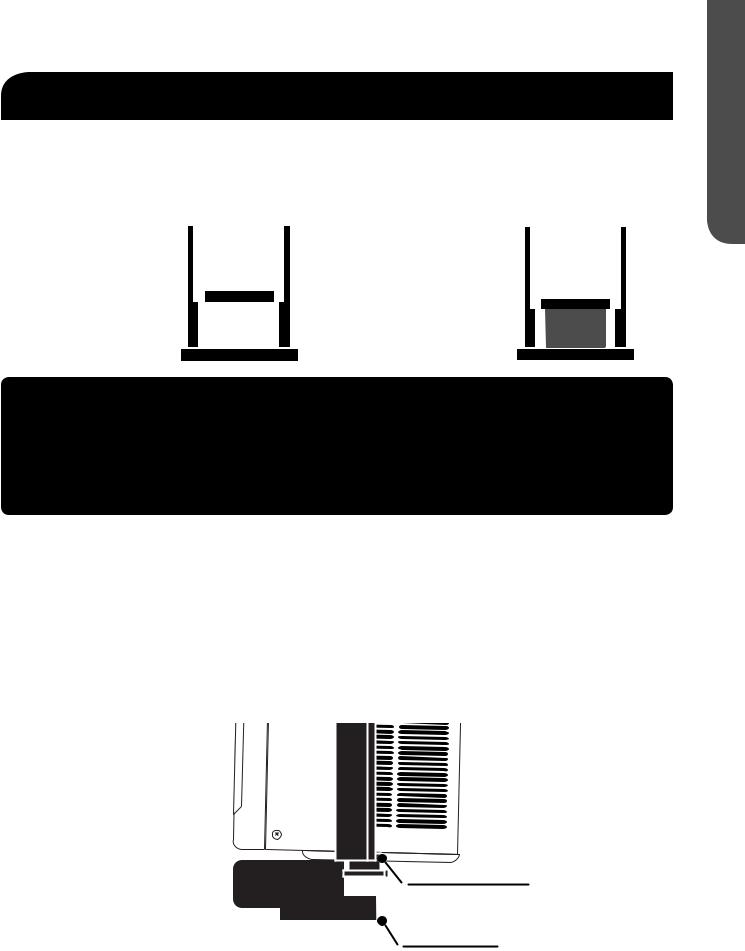
WALL INSTALLATION
Construction and Installation
NOTES:
1.Be certain that the location of the air conditioner in the wall conforms to all local building codes before installation.
2.Consult with a qualified carpenter concerning installation.
3.When installing the air conditioner in a through-the-wall application, work from inside the room.
4.Eachthrough-the-wallinstallationmaybeunique;thereforenoadditionalpartsareincluded.
5.Be certain that the section of the wall being used:
•Doesnothaveelectricalwiringinthelocationwheretheairconditionerwillbeinstalled.
•Doesnothaveplumbingpipesinthelocationwheretheairconditionerwillbeinstalled.
•Anexistingelectricaloutletthatmatchesthepowersupplycordplugoftheairconditioner. Ifno outletexistsorthewrongtypeofmatingoutletispresent,consultwithaqualifiedelectricianto install the proper outlet.
•Doesnotsupportmajorstructuralcomponents.
•Thefinishedsidesofthewallopeningshouldbestructuralwallmembers.
•Outsideareasarenotblocked.
•See “Electrical Requirements" for full detail.
•Structuralintegrityofthewallmustbemaintained.Professionalinstallationisstrongly recommended.
PAGE 20 |
HOW TO INSTALL |
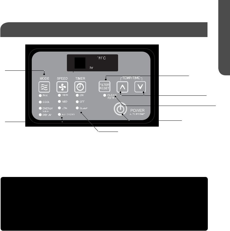
STARTING THE AIR CONDITIONER
MODE
FILTER RESET
TEMPERATURE / TIME
CLEAN FILTER INDICATOR
SPEED |
POWER |
TIMER
* ESA424K does not have Auto Cool / Sleep Mode and Filter Reset.
Operating your air conditioner properly helps you to obtain the best possible results.
This section explains how to operate this air conditioner.
IMPORTANT:
•When you turn off the air conditioner , either at the control panel or with the remote control, wait at least 3 minutes before turning it back on. This prevents the compressor from overloading. This 3 minute delay also applies when switching from cool mode to fan and back.
•Do not operate your air conditioner in the Cool mode when the outside temperature is below
61° (16° C). The inside evaporator coil will freeze up, and the air conditioner will not operate properly.
ENGLISH
USING YOUR AIR CONDITIONER |
PAGE 21 |

ENGLISH
STARTING THE AIR CONDITIONER cont.
1.Carefully remove the clear plastic film from the control panel.
2.Press POWER once to turn on the air conditioner.
NOTE: When the air conditioner is first plugged in, the LED display will show “88” for 3 seconds. After the air conditioner is turned on for the first time, the display will show the temperature 72˚ F and the fan is automatically set to Low speed and the Mode indicator will show ENERGY SAVE.
NOTE: To switch the temperature display between Fahrenheit (F) and Celsius(C), the air conditioner must be plugged in, and turned on. The change cannot be done using the remote control.
• ESA415M, ESA418M: To switch between °F and °C,press UP and DOWN buttons simultaneously and hold for 3 seconds.
• ESA424K: To switch between °F and °C, press POWER button and hold for 5 seconds.
3.Select Mode. Refer to “Mode.”
4.Select Speed. Refer to “Speed.”
5.Set Timer. Refer to “Temp/Time”
6.Reset the filter. Refer to “Filter Reset”
MODE
1.Press mode until you see the indicator light come on next to the desired setting.
2.Choose Fan, Cool, Energy Save, or Dehum.
FAN—Only the fan runs. Press SPEED to select High, Med or Low fan speed. The display shows the current room temperature.
COOL—Cools the room. Press SPEED to select High,Med , Low or Auto Cool fan speed. Press the
TEMP/TIME up or down arrow button to adjust the temperature.
ENERGY SAVE—In this mode the fan runs only when cooling is needed. The fan will run for
3 minute after the compressor shuts off. The fan then cycles on for 1 or 2 minutes at 10 minute intervals until the temperature in the room is above the set temperature. The compressor then turns back on.
DEHUM—Aids in removing humidity from the room. This setting will NOT cool the room.
PAGE 22 |
USING YOUR AIR CONDITIONER |

STARTING THE AIR CONDITIONER cont.
SPEED
1. Press FAN SPEED until; you see the indicator light come on next to
the desired setting. 2. Choose High, Med, Low or Auto Cool
HIGH—For maximum cooling
MED—For normal cooling
LOW—For minimum cooling
AUTO COOL – Adjusts the fan speed automatically to provide ideal cooling based on the room temperature.
TIMER
To set the air conditioner to turn off between 1 hour and 24 hours (The air conditioner must be ON to set):
1.Press TIMER. Timer Off indicator light will flash. The display will show the remaining hours before the air conditioner will turn off.
2.Press the TEMP/TIME up or down arrow button to change the delay time from 1 hour to 24 hours.
3.After 5 seconds, Timer Off indicator light will remain on. The display will show the left time to Timer OFF or the current temperature.
To set the Timer to turn on the air conditioner, keeping the previous settings:
1.Turn on the unit.
2.Press TIMER. Timer On indicator light will flash. The display will show the remaining hours before the air conditioner will turn on.
3.Press the TEMP/TIME up or down arrow button to change the delay time from 1 hour to 24 hours.
4.Timer On indicator light will remain on.
TO SET THE TIMER TO TURN ON THE AC, AND CHANGE THE PREVIOUS SETTINGS:
1.Turn on the air conditioner.
2.Adjust the mode to Fan, Cool, Energy Save or Dehum.
3.For Fan or Dehum mode,adjust the fan speed to High, Med or Low. For Cool or Energy Save mode, adjust the fan speed to High, Med, Low or Auto Cool.
4.Adjust the temperature between 61°F and 86°F (16°C and 30°C).
NOTE: In Fan mode, the temperature cannot be set.
5.Press TIMER. Timer On indicator light will flash. The display will show the remaining hours before the air conditioner will turn on.
6.Press the TEMP/TIME up or down arrow button to change the delay time from 1 hour to 24 hours.
7.Timer On indicator light will remain on.
ENGLISH
USING YOUR AIR CONDITIONER |
PAGE 23 |

ENGLISH
STARTING THE AIR CONDITIONER cont.
TO CLEAR TIMER PROGRAM:
NOTE: Air conditioner can be either on or off.
Press TIMER until Timer indicator light turns off.
TO VIEW OR CHANGE THE REMAINING TIME (IN HOURS):
TIMER OFF
1.Press the TEMP/TIME up or down arrow button to increase or decrease the time.
2.After 5 seconds, the display will show the remaining time to Time OFF or the current temperature.
TIMER ON
1.The display will show the remaining time.
2.Press the TEMP/TIME up or down arrow button to increase or decrease the time.
3.After 5 seconds, the display will show the remaining time to Timer ON.
SLEEP
1.Press the TIMER button to choose Sleep mode. The indicator light will turn on.
2.The temperature will increase by 2˚F 1 hour after the mode is chosen. The temperature then increases another 2˚F after 1 hour. The unit will hold this temperature for 6 hours then stops.
3.To turn off Sleep mode, press the TIMER button until the indicator light is off.
TEMP/TIME
1.Press the TEMP/TIME up arrow button to raise the temperature. Each time you press the
TEMP/TIME up arrow button, the temperature will go up 1°F until it reaches 86°F (30°C).
2.Press the TEMP/TIME down arrow button to lower the temperature. Each time you press the
TEMP/TIME down arrow button, the temperature will go down 1°F until it reaches 61°F (16°C).
NOTE:
• ESA415M ESA418M: After 5 seconds under Fan mode the display will show the current temperature under Cool, Energy Save or Dehum mode the display will show the set temperature
• ESA424K: After 5 seconds the display will show the current temperature.
PAGE 24 |
USING YOUR AIR CONDITIONER |

USING THE REMOTE CONTROL
FILTER RESET
This feature automatically notifies you that the air filter must be cleaned. The indicator light will come on after 240 hours of operation. Clean the air filter (refer to Care and Cleaning), place it back in the front panel, and press the Filter Reset button. The light will turn off.
NOTE: The raised dots are Braille for the visually impaired. (SeeFig.19)
Remote control may differ in appearance from the image shown.
ON/OFF
MODE
SPEED
TIMER
TEMP/TIME
TEMP/TIME
NOTE: Remove and discard protective film prior to use. The remote control runs on one CR2025 battery (included). Replace battery after 6 months of use,
or when the remote control starts to lose power. To change battery, first remove screw on back panel of remote.
POWER
Press ON/OFF to turn on the air conditioner.
Mode
Press MODE to choose Fan, Cool, Energy Save or Dehum.
Speed
Press SPEED to choose High, Med, Low or Auto Cool.
TIMER
To set the air conditioner to turn off after a set amount between 1 hour and 24 hours (unit must be ON):
1.Press TIMER. Timer OFF indicator light on the air conditioner control panel will flash.
2.Press the TEMP/TIME up or down arrow button to change the delay time from 1 hour to 24 hours.
3.After 5 seconds, Timer OFF indicator light on the air conditioner control panel will remain on.
TO SET TIMER TO TURN ON THE AIR CONDITIONER, KEEPING PREVIOUS SETTINGS:
1.Turn on the air conditioner.
2.Press TIMER. Timer On indicator light on the air conditioner control panel will flash
3.Press the TEMP/TIME up or down arrow button to change the delay time from 1 hour to 24 hours.
4.After 5 seconds, Timer On indicator light on the air conditioner control panel will remain on.
ENGLISH
USING YOUR AIR CONDITIONER |
PAGE 25 |

ENGLISH
USING THE REMOTE CONTROL cont.
TO SET TIMER TO TURN ON THE AIR CONDITIONER, AND CHANGE THE PREVIOUS SETTINGS:
1.Turn on the air conditioner.
2.Adjust the mode to Fan,Cool,Energy Save or Dehum.
3.For Fan or Dehum mode,adjust the fan speed to High,Med or Low. For Cool or Energy Save mode,adjust the fan speed to High,Med, Low or Auto Cool.
4.Adjust the temperature between 61°F and 86°F (16°C and 30°C).
NOTE: In Fan mode, the temperature cannot be set.
5.Press TIMER. Timer On indicator light on the air conditioner control panel will flash. Display will show remaining hours before the air conditioner will turn on.
6.Press the TEMP/TIME up or down arrow button to change the delay time from 1 hour to 24 hours.
7.Timer On indicator light on the air conditioner control panel will remain on.
TO CLEAR TIMER DELAY PROGRAM:
NOTE: Air conditioner can be either on or off.
Press TIMER until Timer indicator light turns off.
TO SEE OR CHANGE THE REMAINING TIME (IN HOURS):
TIMER OFF:
1.Press the TEMP/TIME up or down arrow button to increase or decrease the time.
2.After 5 seconds, the display on the air conditioner control panel will show will show the remaining time to Timer Off or the current room temperature.
TIMER ON:
1.Display on the air conditioner control panel will show remaining time.
2.Press the TEMP/TIME up or down arrow button to increase or decrease the time.
PAGE 26 |
USING YOUR AIR CONDITIONER |
USING THE REMOTE CONTROL cont.
SLEEP
1.Press the TIMER button to choose Sleep mode. The indicator light will turn on.
2.The temperature will increase by 2˚F 1 hour after the mode is chosen. The temperature then increases another 2˚F after 1 hour. The unit will hold this temperature for 6 hours then stops.
3.To turn off Sleep mode, press the TIMER button until the indicator light is off.
TEMP/TIME
•Press the TEMP/TIME up arrow button to raise the temperature. Each time you press the TEMP/ TIME up arrow button, the temperature will go up 1°F until it reaches 86°F (30°C).
•Press the TEMP/TIME down arrow button to lower the temperature. Each time you press or hold the TEMP/TIME down arrow button, the temperature will go down 1°F until it reaches 61°F
(16°C).
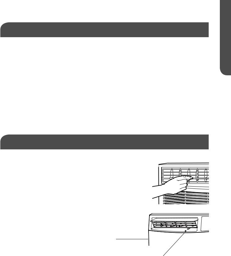
CHANGING THE AIR DIRECTION
The air directional louvers let you control the direction of the airflow. The airflow can be directed up-down or left to right. (SeeFig.32)
Vent: The Fresh Air vent allows the air conditioner to recirculate Fig. 32
inside air, draw fresh air into the room, and exhaust stale air to the outside.
NOTE: For models ESA415M ESA418M (SeeFig.33)
4-Way Air Flow 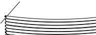
Fig. 33
Vent
ENGLISH
USING YOUR AIR CONDITIONER |
PAGE 27 |
 Loading...