

GW Instek PST User Manual
PST-3201/3202 PROGRAMMABLE POWER SUPPLY
PST-3201/3202 PROGRAMMABLE POWER SUPPLY
USER MANUAL
CONTENTS PAGE
1. PRODUCT INTRODUCTION......................... ........... ........... ..
1-1. Description………………………………………………
1-2. Feature…………………………………………………...
2. TECHNICAL SPECIFICATIONS…………………………
3. PRECAUTIONS BEFORE OPERATION…….…………...
3-1. Unpacking the Instrument……………….………….….
3-2. Checking the Line Voltage…………………..………….
3-3. Environment……………………………………..……...
4. PANEL INTRODUCTION……………………..…………...
5.
OPERATION METHOD………………………………...….
5-1. Output Voltage/Current Setting…………………..……
5-2. Over Voltage/Current Protection Setting……………...
5-3. Voltage/Current Step Setting…………………………..
5-4. Information Storing & Recalling Setting………………
5-5. Information Editing & Copying Setting……………….
5-6. Auto Operation Mode….……………………………….
5-7. Parallel Operation Mode…………………………….….
5-8. Track Operation Mode…………………………………
5-9. GPIB/RS-232 Interface Setting…………………………
5-10.The Maximum Output Setting………………………....
5-11.Test Lead………………………………………………..
5-12. The Setting of the GPIB and RS 232 Interf ace………..
6.
MAINTENANCE………………………..…………………..
6-1. Fuse Replacement……………………………………….
6-2. Line Voltage Conversion………………………………..
6-3. Adjustment and Calibration……………………………
6-4. Cleaning…………………………………………………
7.
THE SYSTEM DIAGRAM AND DESCRIPTION………..
7-1.Block Diagram…………………………………………...
7-2.The Operation of the whole circuit……………………...
1
1
1
3
5
5
5
6
7
11
11
12
13
13
15
16
17
17
18
19
20
20
21
21
21
22
28
29
29
30
USER MANUAL
SAFETY TERMS AND SYMBOLS
These terms may appear in this manual or on the product:
WARNING. Warning statements identify condition or practices that
could result in injury or loss of life.
CAUTION. Caution statements identify conditions or practices that
could result in damage to this product or other property.
WARNING: This equipment is not for measurements performed for
CAT II, III and IV.
Measurement category I is for measurements performed on circuits not directly
connected to MAINS.
Measurement category II is for measurements performed on circuits directly
connected to the low voltage installation.
Measurement category III is for measurements performed in the building
installation.
Measurement category IV is for measurements performed at the source of the lowvoltage installation.
The following symbols may appear in this manual or on the product:
DANGER ATTENTION Protective Earth (ground) Frame or Chassis
High Voltage refer to Manual Conductor Terminal Terminal
Terminal
⎯ ⎯
i
⎯ ⎯
ii
PST-3201/3202 PROGRAMMABLE POWER SUPPLY
PST-3201/3202 PROGRAMMABLE POWER SUPPLY
USER MANUAL
FOR UNITED KINGDOM ONLY
NOTE: This lead/appliance must only be wired by competent persons
WARNING: THIS APPLIANCE MUST BE EARTHED
IMPORTANT: The wires in this lead are coloured in accordance with
the following code:
Green/ Yellow: Earth
Blue: Neutral
Brown: Live (Phase)
As the colours of the wires in main leads may not correspond with the
colours marking identified in your plug/appliance, proceed as follows:
USER MANUAL
This cable/appliance should be protected by a suitably rated and
approved HBC mains fuse: refer to the rating information on the
equipment and/or user instructions for details. As a guide, cable of
0.75mm
2
should be protected by a 3A or 5A fuse. Larger conductors
would normally require 13A types, depending on the connection
method used.
Any moulded mains connector that requires removal /replacement
must be destroyed by removal of any fuse & fuse carrier and disposed
of immediately, as a plug with bared wires is hazardous if a engaged
in live socket. Any re-wiring must be carried out in accordance with
the information detailed on this label.
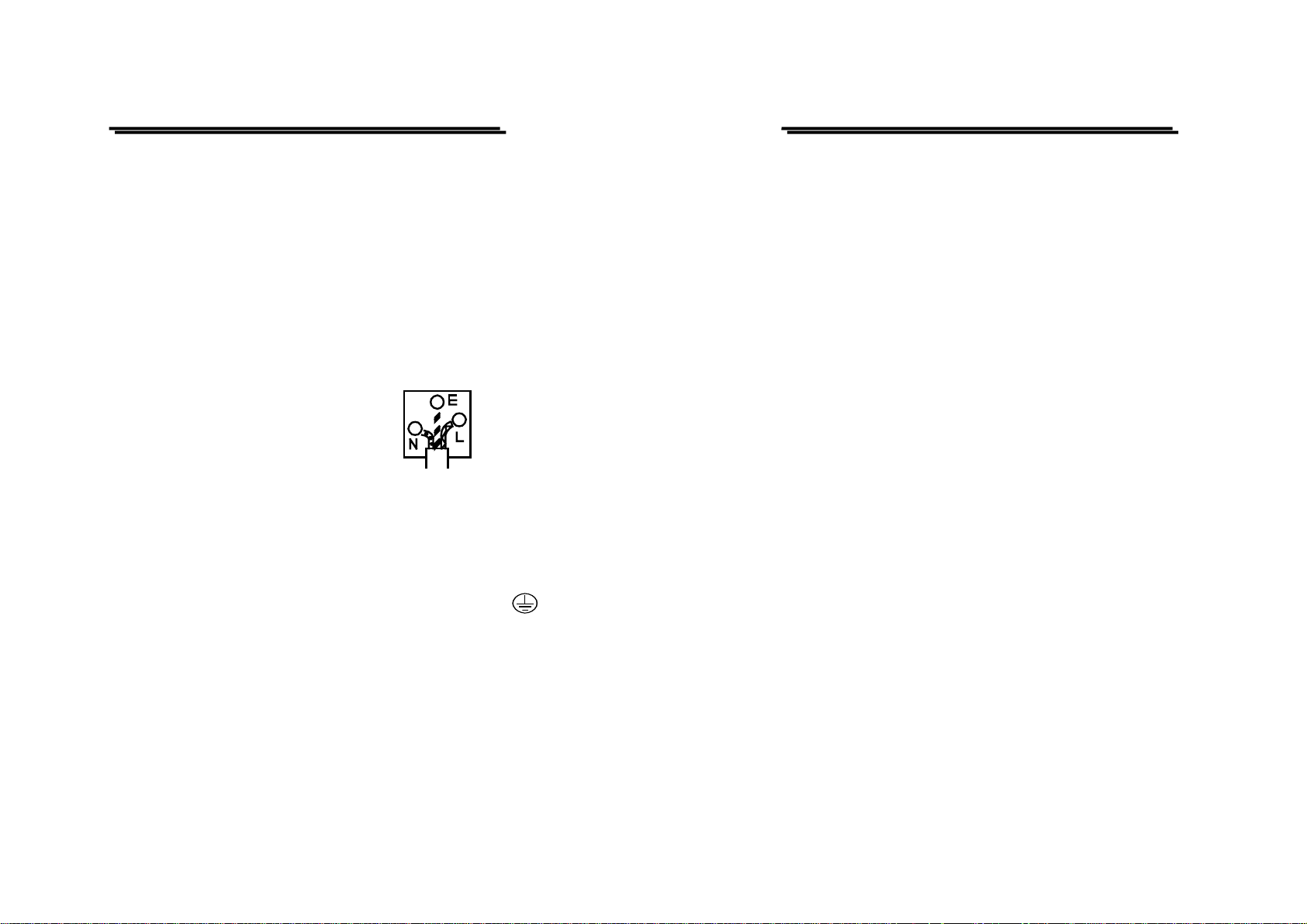
The wire which is coloured Green & Yellow must be connected to the
Earth terminal marked with the letter E or by the earth symbol
or coloured Green or Green & Yellow.
The wire which is coloured Blue must be connected to the terminal
which is marked with the letter N or coloured Blue or Black.
The wire which is coloured Brown must be connected to the terminal
marked with the letter L or P or coloured Brown or Red.
If in doubt, consult the instructions provided with the equipment or
contact the supplier.
⎯ ⎯
iii
⎯ ⎯
iv
PST-3201/3202 PROGRAMMABLE POWER SUPPLY
PST-3201/3202 PROGRAMMABLE POWER SUPPLY
USER MANUAL
Declaration of Conformity
We
GOOD WILL INSTRUMENT CO., LTD.
No. 7-1, Jhongsing Rd., Tucheng City, Taipei County 236, Taiwan
GOOD WILL INSTRUMENT (SUZHOU) CO., LTD.
No. 69 Lushan Road, Suzhou New Distri ct Jian gsu, C hin a.
declares that the below mentioned products
PST-3201, PST-3202
are herewith confirmed to comply with the requirements set out in the Council Directive on
the Approximation of the Law of Member States relating to Electromagnetic Compatibility
(89/336/EEC, 93/68/EEC) and Low Voltage Equipment Directive (73/23/EEC,
93/68/EEC). For the evaluation regarding the Electromagnetic Compatibility and Low
Voltage Equipment Directive, the following standards were applied:
◎ EMC
EN 61326-1: Electrical equipment for measurement, control and laboratory use
–– EMC requirements (1997+A1: 1998)
Conducted and Radiated Emissions
EN 55011: 1991+A1: 1997+A2: 1996
Current Harmonic
EN 61000-3-2: 1995+A1: 1998+A2: 1998 +A14: 2000
Voltage Fluctuation
EN 61000-3-3: 1995
-------------------------
-------------------------
-------------------------
◎ Safety
Low Voltage Equipment Directive 73/23/EEC & amended by 93/68/EEC
IEC/EN 61010-1: 2001
Electrostatic Discharge
EN 61000-4-2: 1995
Radiated Immunity
EN 61000-4-3: 1996
Electrical Fast Transients
EN 61000-4-4: 1995
Surge Immunity
EN 61000-4-5: 1995
Conducted Susceptibility
EN 61000-4-6: 1996
Voltage Dips/ Interrupts
EN 61000-4-11: 1994
USER MANUAL
1. PRODUCT INTRODUCTION
1-1.Description
PST-series Programmable Power Supply is controlled by Micro
Processor Unit (MPU) that can easily connect communication interface
RS-232 or GPIB to computer in order to satisfy users’ demand for autotesting and auto -co ntro l.
The voltage and current are completely controlled by 12 bits D/A
Converter with higher resolution and accuracy. Also, the digitalization of
system makes a speedy, precise and convenient input of information
controlled by keyboard.
The adjustment of voltage/current is made by software calibration
without manual error that will increase the preciseness of the instrument.
The function of Over Voltage Protection (OVP) and Over Current
Protection (OCP) is set with software and detected with hardware to
achieve protected function precisely and speedily in order to secure user s
from danger by using the instrument.
1-2. Feature
1) An overall digitalization of programmable interface with high
resolution.
2) The 192×128 LCD Display can appear multiple settings and
measurement results simultaneously.(The display mode is
changeable).
⎯ ⎯
v
1

PST-3201/3202 PROGRAMMABLE POWER SUPPLY
PST-3201/3202 PROGRAMMABLE POWER SUPPLY
USER MANUAL
3) Intuitional, intelligent interface window display is convenient for
user to operate the instrument.
4) High stability and low draft.
5) The function of over voltage/current/temperature pro tection.
6) Intelligent control fan (Vary with different output power.)
7) Warning signal by the built-in Buzzer.
8) Step by step calibration procedure.
9) Brand new panel design and the 1/2 rack size reduction volume
design.
10) Wheel knob of Fine and Coarse.
11) 100 groups storage space setting.
12) Parallel and series operation modes.
13) IEEE-488.2 and SCPI compatible command setting.
14) 0.1 sec timer for output working loop (Auto step running)
15) Correspond to CE safety regulation.
USER MANUAL
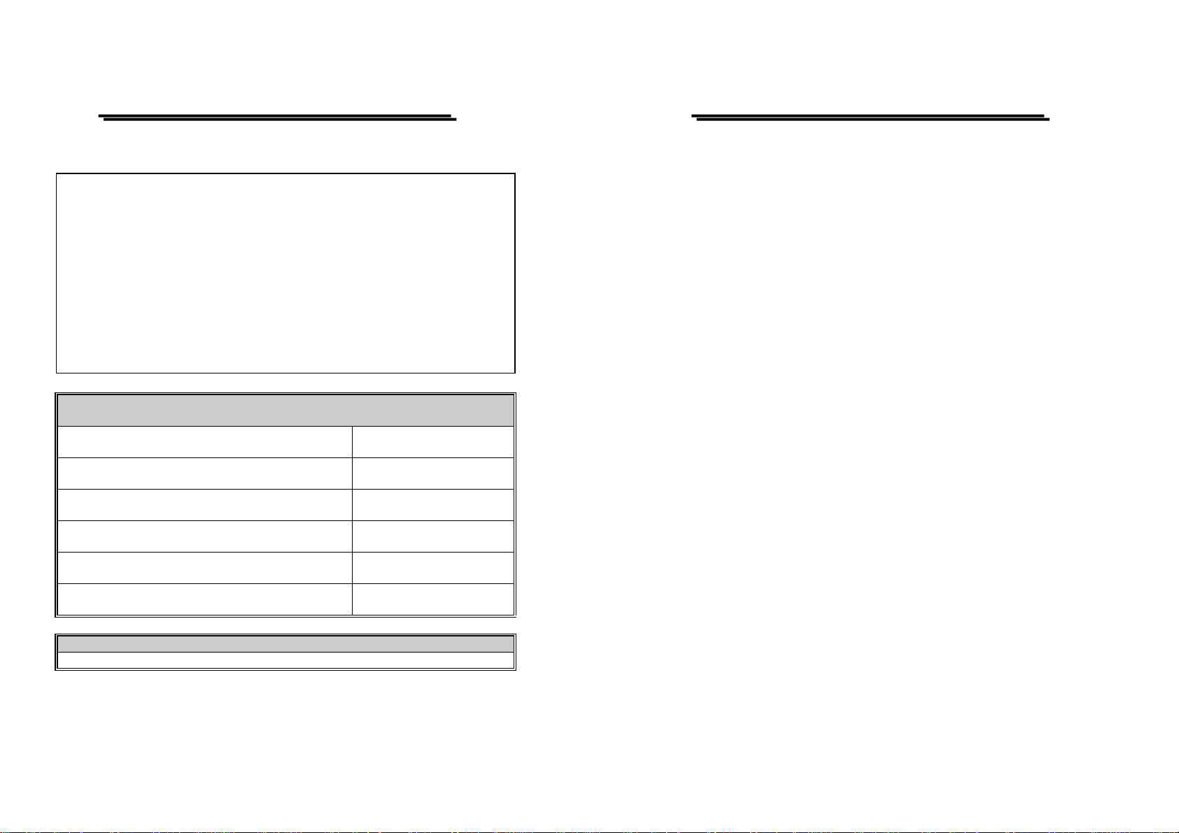
2. TECHNICAL SPECIFICATIONS
SPECIFICATIONS PST-3201 PST-3202
Voltage 0-32V×3 0-32V×2, 0-6V×1
Current 0-1A×30-2A×2, 0-5A×1Output
OVP 0-33V×3 0-33V×2, 0-7V×1
Voltage ≦3mV(≦5mV rating current>3.0A), test points are
at the + output terminal and - output terminal point.
Load Effect
Source Effect
Resolution
Program
Accuracy
(25±5℃)
Ripple & Noise
(20Hz~20MHz)
Coefficient
(0~40℃)
Resolution
Response Time
Voltage Up
Voltage Down
Temperature
Coefficient
Drift
Current ≦3mA(≦5mA rating current>3.0A) , test points
are at the + output terminal and - output terminal
point.
Voltage ≦3mV, test points are at the + output terminal and -
output terminal point.
Current ≦3mA, test points are at the + output terminal and -
output terminal point.
Voltage
Current 1mA(2mA rating current>3.0A)
OVP 10mV
Voltage ≦0.05%+20mV
Current ≦0.1%+5mA(+10mA rating current> 3.0A)
OVP ≦0.05%+20mV
Voltage Ripple≦1mVrms/3mVp-p
Current ≦3mArms(≦5mArms rating current>3.0A)
Voltage ≦100ppm+3mVTemperature
Current ≦100ppm+3mA
Voltage 10mVReadback
Current 1mA(2mA rating current >3.0A)
10%~90% ≦100ms
90%~10% ≦100ms (≧10% rating load)
Voltage ≦100ppm+10mVReadback
Current ≦150ppm+10mA
Voltage ≦100ppm+10mV
Current ≦150ppm+10mA
10mV
Noise≦2mVrms/30mVp-p
⎯ 2 ⎯
⎯ 3 ⎯
PST-3201/3202 PROGRAMMABLE POWER SUPPLY
PST-3201/3202 PROGRAMMABLE POWER SUPPLY
USER MANUAL
Track Operation
Parallel
Operation
Memory Store/Recall points 0~99
Interface RS232, GPIB interface option
Power Source AC100V, 120V, 220V±10%, 230V +10%/-6% 50/60Hz.
Power
Consumption
Mechanical Spec.
Operation
Environmental
Storage
Temperature &
Humidity
Accessories
Tracking
Error
Series (Load
Effect)
Program
Accuracy
Load Effect
Source
Effect
Setting time 0.1sec~99min59sec(max × 100)
Resolution- 0.1secTimer
Function For output working loop (Auto Step running)
PST-3201: 210W
PST-3202: 360W
Dimensions 230(W)×140(H)×380(D) mm.
Weights 10 kg
Indoor use, Altitude up to 2000 m
Ambient temperature :
To satisfy specifications : 10℃ to 35℃ ( 50° F to 95°F )
Maximum operating ranges: 0℃ to 40℃( 32°F to 104°F )
Relative humidity: 85% RH(max.) non condensing
Installation Category: II
Pollution degree: 2
-10℃ to 70℃, 70%RH (maximum)
Power cord….............…………× 1
Instruction manual……………..× 1
Programmer manual................. × 1
Test Lead……….…………….. × 3
≦0.1%+20mV
≦20mV
Voltage≦0.05%+20mA
Current≦0.1%+10mA
OVP≦0.05%+20mA
Voltage≦3mV(≦5mV rating current>3. 0A)
Current≦6mA, test points are at the + output
terminal and – output termi nal poin t.
Voltage≦3mV, Current≦6mA, test points are at
the + output terminal and – output terminal point.
USER MANUAL
3. PRECAUTIONS BEFORE OPERATION
3-1.Unpacking the Instrument
The product has been fully inspected and tested before shipping from the
factory. Upon receiving the instrument, please unpack and inspect it to
check if there is any damage caused during transportation. If any sign of
damage is found, notify the bearer and/or the dealer immediately.
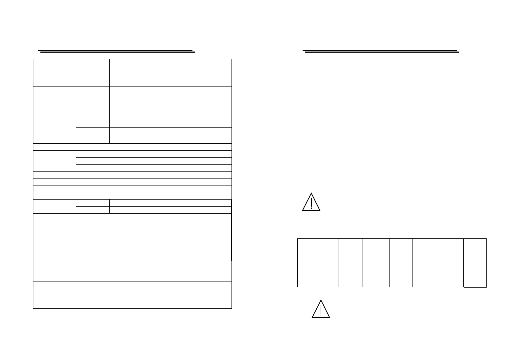
3-2.Checking the Line Voltage
The product can be applie d by any kind of line vo ltages shown in the table
below. Before connecting the power plug to an AC line outlet, make sure
the voltage selector of the rear panel is set to the correct position
corresponding to the line voltage. It might be damaged the instrument by
connecting to the wrong AC line voltage.
WARNING. To avoid electrical shock the power cord
protective grounding conductor must be connected to
ground.
When line voltages are changed, replace the required fuses shown as below:
Model
PST-3201
PST-3202
Line
voltage
100V
120V
WARNING. To avoid personal injury, disconnect the power
cord before removing the fuse holder.
Input
Range
90-110V
108-132V
Fuse
T3A
250V
T5A
250V
Line
voltage
220V
230V
Input
Range
198-242V
216-253V
Fuse
T1.6A
250V
T2.5A
250V
⎯ 4 ⎯
⎯ 5 ⎯
PST-3201/3202 PROGRAMMABLE POWER SUPPLY
PST-3201/3202 PROGRAMMABLE POWER SUPPLY
USER MANUAL
3-3.Environment
The normal ambient temperature range of this instrument is from 0° to 40°C
(32° to 104°F). To operate the instrument exceeding this specific
temperature range may cause damage to the circuits of instrument.
Do not use the instrument in a place where strong ma gnetic or electric field
exists as it may disturb the measurement.
USER MANUAL
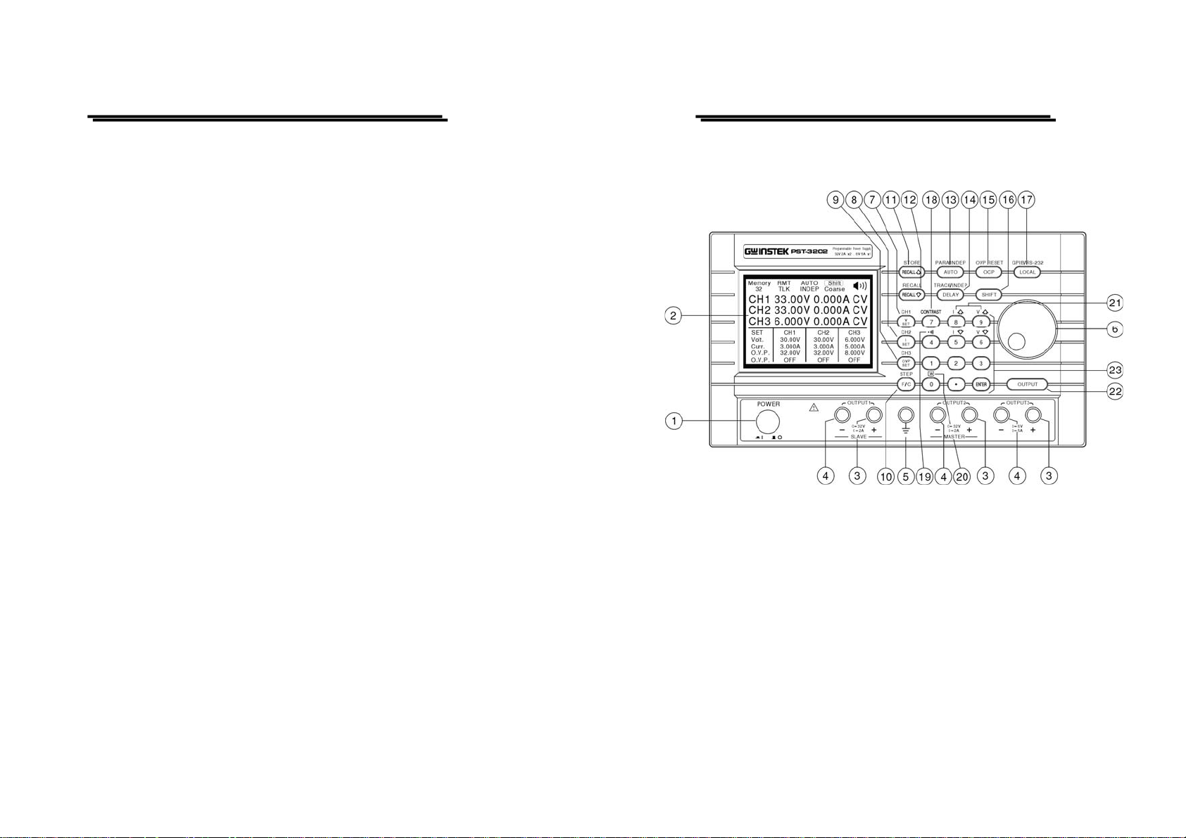
4. PANEL INTRODUCTION
⎯ 6 ⎯
Figure 4-1 Front Panel
⎯ 7 ⎯
 Loading...