

GW Instek GPT-9601, GPT-9602, GPT-9612, GPT-9603 User guide
Electrical Safety Tester
GPT-9600 Series
USER MANUAL
GW INSTEK PART NO. 82PT-96030EA1
ISO-9001 CERTIFIED MANUFACTURER
This manual contains proprietary information, which is protected by copyright. All rights are reserved. No part of this manual may be photocopied, reproduced or translated to another language without prior written consent of Good Will company.
The information in this manual was correct at the time of printing. However, Good Will continues to improve products and reserves the rights to change specification, equipment, and maintenance procedures at any time without notice.
Good Will Instrument Co., Ltd.
No. 7-1, Jhongsing Rd., Tucheng Dist., New Taipei City 236, Taiwan.

Table of Contents |
|
Table of Contents |
|
SAFETY INSTRUCTIONS ................................................... |
4 |
GETTING STARTED ........................................................... |
8 |
GPT-9600 Series Overview ..................... |
9 |
Appearance .......................................... |
12 |
Set Up.................................................. |
18 |
OPERATION .................................................................... |
24 |
Menu Tree ............................................ |
25 |
Test Lead Connection ........................... |
29 |
ACW, DCW and IR Testing .................... |
33 |
Common Utility Settings ...................... |
55 |
EXTERNAL CONTROL ..................................................... |
59 |
External Control Overview .................... |
60 |
FAQ ................................................................................ |
66 |
APPENDIX ...................................................................... |
68 |
Fuse Replacement ................................ |
68 |
Error Messages .................................... |
69 |
GPT-9600 Specifications ...................... |
70 |
GPT-9600 Dimensions ......................... |
73 |
Declaration of Conformity .................... |
74 |
INDEX............................................................................. |
75 |
3
SAFETY INSTRUCTIONS
SAFETY INSTRUCTIONS
This chapter contains important safety instructions that you must follow during operation and storage. Read the following before any operation to ensure your safety and to keep the instrument in the best possible condition.
Safety Symbols
These safety symbols may appear in this manual or on the instrument.
Warning: Identifies conditions or practices that
WARNING |
could result in injury or loss of life. |
|
|
||
CAUTION |
Caution: Identifies conditions or practices that |
|
could result in damage to the instrument or to |
||
|
||
|
other properties. |
|
|
DANGER High Voltage |
|
|
Attention Refer to the Manual |
|
|
Protective Conductor Terminal |
|
|
Frame or Chassis Terminal |
|
|
Earth (ground) Terminal |
4

SAFETY INSTRUCTIONS
Do not dispose electronic equipment as unsorted municipal waste. Please use a separate collection facility or contact the supplier from which this instrument was purchased.
Safety Guidelines
General
Guideline
 CAUTION
Do not place any heavy object on the instrument.
Avoid severe impact or rough handling that leads to damaging the instrument.
Do not discharge static electricity to the instrument.
Use only mating connectors, not bare wires, for the terminals.
Do not block the cooling fan opening.
Do not disassemble the GPT-9600 unless you are qualified.
(Measurement categories) EN 61010-1:2010 specifies the measurement categories and their requirements as follows. The GPT-9600 does not fall under category II, III or IV.
Measurement category IV is for measurement performed at the source of low-voltage installation.
Measurement category III is for measurement performed in the building installation.
Measurement category II is for measurement performed on the circuits directly connected to the low voltage installation.
Power Supply
 WARNING
AC Input voltage range: 100-120/220-240VAC ±10%
Frequency: 50Hz/60Hz
Fuse: T 4A 250V
To avoid electrical shock connect the protective grounding conductor of the AC power cord to an earth ground.
5

GPT-9600 Series User Manual
Cleaning the
GPT-9600
Disconnect the power cord before cleaning.
Use a soft cloth dampened in a solution of mild detergent and water. Do not spray any liquid.
Do not use chemicals containing harsh material
|
|
such as benzene, toluene, xylene, and acetone. |
Operation |
|
Location: Indoor, no direct sunlight, dust free, |
Environment |
|
almost non-conductive pollution (Note below) |
|
Relative Humidity: ≤ 70% (no condensation) |
|
|
|
Altitude: < 2000m |
|
|
Temperature: 0˚C~40˚C |
|
(Pollution Degree) EN 61010-1:2010 specifies the pollution degrees |
|
|
and their requirements as follows. The GPT-9600 falls under degree |
|
|
2. |
|
|
Pollution refers to “addition of foreign matter, solid, liquid, or |
|
|
gaseous (ionized gases), that may produce a reduction of dielectric |
|
|
strength or surface resistivity”. |
|
|
Pollution degree 1: No pollution or only dry, non-conductive |
|
|
|
pollution occurs. The pollution has no influence. |
|
Pollution degree 2: Normally only non-conductive pollution |
|
|
|
occurs. Occasionally, however, a temporary conductivity caused |
|
|
by condensation must be expected. |
|
Pollution degree 3: Conductive pollution occurs, or dry, non- |
|
|
|
conductive pollution occurs which becomes conductive due to |
|
|
condensation which is expected. In such conditions, equipment |
|
|
is normally protected against exposure to direct sunlight, |
|
|
precipitation, and full wind pressure, but neither temperature |
|
|
nor humidity is controlled. |
Storage |
|
Location: Indoor |
environment |
|
Temperature: -10°C to 70°C |
|
||
|
Relative Humidity: ≤ 85% (no condensation) |
|
|
|
|
Disposal |
Do not dispose this instrument as unsorted |
|
|
municipal waste. Please use a separate collection |
|
|
facility or contact the supplier from which this |
|
|
instrument was purchased. Please make sure |
|
discarded electrical waste is properly recycled to reduce environmental impact.
6
SAFETY INSTRUCTIONS
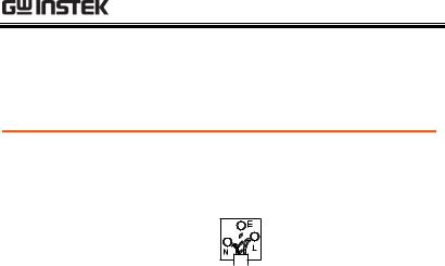
Power cord for the United Kingdom
When using the safety tester in the United Kingdom, make sure the power cord meets the following safety instructions.
NOTE: This lead/appliance must only be wired by competent persons
 WARNING: THIS APPLIANCE MUST BE EARTHED
IMPORTANT: The wires in this lead are coloured in accordance with the following code:
Green/ Yellow: Blue:
Brown:
As the colours of the wires in main leads may not correspond with the coloured marking identified in your plug/appliance, proceed as follows:
The wire which is coloured Green & Yellow must be connected to the Earth terminal marked with either the letter E, the earth symbol  or coloured Green/Green & Yellow.
The wire which is coloured Blue must be connected to the terminal which is marked with the letter N or coloured Blue or Black.
The wire which is coloured Brown must be connected to the terminal marked with the letter L or P or coloured Brown or Red.
If in doubt, consult the instructions provided with the equipment or contact the supplier.
This cable/appliance should be protected by a suitably rated and approved HBC mains fuse: refer to the rating information on the equipment and/or user instructions for details. As a guide, a cable of 0.75mm2 should be protected by a 3A or 5A fuse. Larger conductors would normally require 13A types, depending on the connection method used.
Any exposed wiring from a cable, plug or connection that is engaged in a live socket is extremely hazardous. If a cable or plug is deemed hazardous, turn off the mains power and remove the cable, any fuses and fuse assemblies. All hazardous wiring must be immediately destroyed and replaced in accordance to the above standard.
7
GPT-9600 Series User Manual
GETTING STARTED
This chapter describes the safety tester in a nutshell, including its main features and front / rear panel introduction. After going through the overview, please read the safety considerations in the Set Up chapter.
GPT-9603 |
Tester |
|
CAUTION |
START |
STOP |
|
REMOTE |
POWER |
|
GPT-9600 Series Overview ................................................. |
9 |
Series lineup................................................................................................ |
9 |
Model Overview......................................................................................... |
9 |
Main Features ............................................................................................. |
9 |
Accessories and Package Contents ........................................................ |
10 |
Appearance ..................................................................... |
12 |
GPT-9603/9602/9612/9601 Front Panel ............................................... |
12 |
GPT-9603/9602/9612/9601 Rear Panel ................................................ |
16 |
Set Up............................................................................. |
18 |
Power Up................................................................................................... |
18 |
Workplace Precautions............................................................................ |
20 |
Operating Precautions............................................................................. |
21 |
Basic Safety Checks .................................................................................. |
23 |
8

GETTING STARTED
GPT-9600 Series Overview
Series lineup
The GPT-9600 Series Safety Testers are AC/DC withstanding voltage and insulation resistance safety testers.
The GPT-9603 is an AC/DC withstanding and insulation resistance safety tester.
The GPT-9602 is an AC/DC withstanding safety tester.
The GPT-9612 is an AC withstanding and insulation resistance safety tester.
The GPT-9601 is purely an AC withstanding safety tester.
Note: Throughout this user manual, the terms ACW, DCW and IR refer to AC Withstanding, DC Withstanding and Insulation Resistance, respectively. GPT-9600 refers to any of the GPT-96XX models.
Model Overview
Model name |
ACW |
DCW |
IR |
GPT-9603 |
|
|
|
|
|
|
|
|
|
|
|
GPT-9602 |
|
|
|
|
|
|
|
GPT-9612 |
|
|
|
|
|
|
GPT-9601 |
|
|
|
|
|
Main Features |
|
Performance ACW: 5kVAC
DCW: 6kVDC
IR: 50V, 100V, 250V, 500V, 1000V
9

GPT-9600 Series User Manual
Features |
|
Timer control |
|
|
Safety discharge |
|
Over temperature, voltage and current |
|
|
|
protection |
|
Pass, Fail, Test, High Voltage and Ready |
|
|
|
indicators |
|
PWM output (increased reliability) |
|
|
|
Interlock (configurable) |
|
|
|
Interface |
|
Remote control start/stop interface terminal |
|
Signal I/O port for pass/fail/test monitoring |
|
|
|
and start/stop control/interlock |
Accessories and Package Contents
Check the package contents to make sure all accessories and optional items are included before using the GPT-9600.
Standard Accessories |
Part number |
Description |
|
N/A |
GPT-96XX unit. |
|
N/A |
User manual CD |
|
N/A |
Quick start guide |
|
GHT-114 x1 |
Test lead |
|
Region dependent |
Power cord |
|
N/A |
Remote terminal male plug |
|
N/A |
Interlock key |
|
N/A |
CTC (Calibration Traceable |
|
|
Certificate) |
Optional Accessories |
Part number |
Description |
|
GHT-205 |
High voltage test probe |
|
GHT-113 |
High voltage test pistol |
10 |
|
|
|
|
GETTING STARTED |
|
|
|
|
|
|
|
|
|
|
GRA-417 |
Rack adapter panel |
|
|
|
(19”, 4U) |
|
Keep the packaging, including the box, polystyrene Note foam and plastic envelopes should the need arise
to return the unit to GW Instek.
11

GPT-9600 Series User Manual
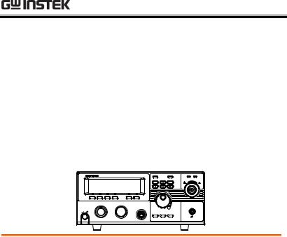
Appearance
GPT-9603/9602/9612/9601
Front Panel
|
PASS/FAIL indicators |
|
|
Display |
Function keys |
Navigation keys |
READY indicator |
GPT-9603 |
AC / DC Withstanding Voltage / |
PASS |
FAIL |
READY |
TEST |
TEST indicator |
Insulation Resistance |
Tester |
|
|
|
|
|
|
|
|
|
CAUTION |
5.0 kVAC MAX. |
|
|
|
|
|
HIGH VOLTAGE |
6.0 kVDC MAX. |
|
|
|
ESC |
FIELD |
|
|
HIGH VOLTAGE |
|
|
|
|
|
|
|
|
|
|
|
|
|
indicator |
START |
STOP |
|
|
|
|
HIGH VOLTAGE |
|
|
REMOTE |
|
RETURN |
output terminal |
|
|
|
|
|
|
||
POWER |
|
|
|
|
|
|
POWER |
|
EDIT |
SAVE |
UTILITY |
|
|
|
RETURN |
|
button |
|
|
|
|
|
|
|
terminal |
|
|
|
|
|
|
START button |
REMOTE terminal |
|
Scroll wheel |
|
STOP button |
Configuration keys |
|||
Display
Function keys
Pass/Fail indicators
Navigation keys
240 X 48 dot matrix display (LCD)
The function keys correspond to the soft-keys directly above on the main display.
PASS FAIL |
The PASS and FAIL indicators |
|
|
|
light up upon a PASS or FAIL test |
|
result. |
ESC key
FIELD key
ESC
FIELD
The ESC key is used to exit out of a menu or cancel a setting.
The FIELD key is navigate to the next menu item when the tester is either in the EDIT status or in one of the Utility menus.
12
|
GETTING STARTED |
|
|
|
|
Directional |
The directional arrow keys are |
arrow keys |
only used for calibration. They are |
|
not used during normal operation |
|
by the operator. The directional |
|
arrow keys can essentially be |
|
ignored by the operator. |
READY indicator
TEST indicator
READY
TEST
The READY indicator is lit when the tester is ready to begin testing.
The TEST indicator is lit when a test is on. The START button is used to put the tester into TEST status from READY status.
HIGH VOLTAGE indicator
CAUTION |
5.0 kVAC |
MAX. |
HIGH VOLTAGE |
6.0 kVDC |
MAX. |
The HIGH VOLTAGE indicator will flash when the output terminal is active. Only after the test has finished or stopped will the indicator turn off.
HIGH VOLTAGE output terminal
CAUTION |
5.0 kVAC |
MAX. |
HIGH VOLTAGE |
6.0 kVDC |
MAX. |
The HIGH VOLTAGE terminal output is used for outputting the testing voltage. The terminal is recessed for safety. This terminal is used in conjunction with the RETURN terminal.
 WARNING
USE EXTREME CAUTION.
Do not touch the HIGH VOLTAGE terminal during testing.
13
GPT-9600 Series User Manual
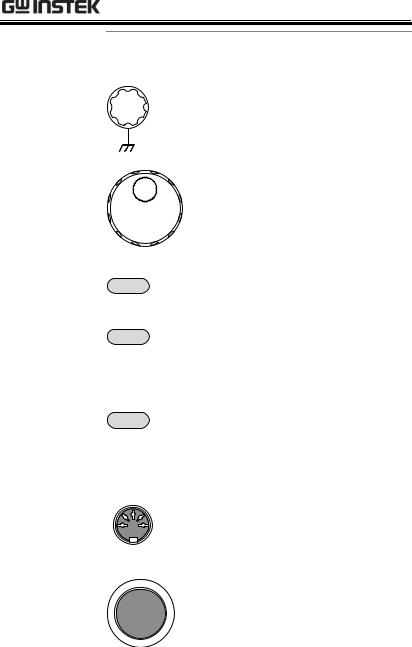
RETURN terminal
RETURN
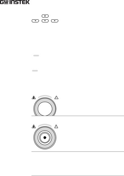
Scroll wheel
UTILITY key |
UTILITY |
|
|
EDIT key |
EDIT |
SAVE key |
SAVE |
|
REMOTE |
REMOTE |
terminal |
|
STOP button |
STOP |
|
14
The RETURN terminal is used for IR, DCW and ACW tests.
The scroll wheel is used to edit parameter values or menu settings.
Used to enter the TEST Utility or Common Utility menu.
Used to enter the EDIT status. The EDIT status allows you to select the test mode and the test parameters.
The SAVE key is used to save test parameters when in the EDIT status or to save utility settings.
The REMOTE terminal is used to connect to a remote controller.
The STOP button is used to stop/cancel tests. The STOP button will also put the safety tester in the READY status to begin testing.
GETTING STARTED
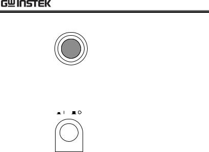
START button |
START |
|
POWER switch POWER
The START button is used to start tests.
The START button can be used to start tests when the tester is in the READY status. Pressing the START button will put the tester in the TEST status.
Turns the power on. The safety tester will always start up with the last test setting from when the instrument was last powered down.
15
GPT-9600 Series User Manual
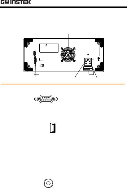
GPT-9603/9602/9612/9601 Rear Panel
Calibration port |
Fan |
|
|
GND |
WARNING |
|
|
|
|
TO AVOID ELECTRIC SHOCK THE POWER CORD |
|
|
|
|
PROTECTIVE GROUNDING CONDUCTOR MUST BE |
|
|
|
|
CONNECTED TO GROUND. |
|
|
|
|
FOR CONTINUED FIRE PROTECTION. REPLACE |
|
|
|
|
ONLY WITH SPECIFIED TYPE AND RATED FUSE. |
|
|
|
|
NO OPERATOR SERVICEABLE COMPONENTS INSIDE. |
|
|
|
|
DO NOT REMOVE COVERS. REFER SERVICING TO |
|
|
|
|
QUALIFIED PERSONNEL. |
|
|
|
|
CALIBRATION |
|
|
|
|
USE ONLY |
|
|
|
|
|
ENSURE THE POWER IS |
|
||
|
REMOVED FROM THE INSTRUMENT |
GND |
||
|
BEFORE REPLACING THE FUSE |
|
||
SER. NO. LB |
|
|
|
|
SIGNAL I / O |
|
|
AC |
|
|
|
POWER |
|
|
|
|
|
MAX. |
|
|
|
|
400VA |
|
|
LINE VOLTAGE |
FUSE |
|
|
|
( 50 / 60Hz ) |
|
||
|
100 |
120V |
T 4A |
|
|
220 |
240V |
250V |
|
SIGNAL I/O
SIGNAL I/O port |
SIGNAL I / O |
|
Calibration port
CALIBRATION
USE ONLY
Fan/Fan Vents
GND |
|
|
|
|
|
|
GND |
|
|
|
|
|
|
|
|
||
|
|
|
|
|
|
|
|
|
|
|
|
|
|
|
|
|
|
|
|
|
|
|
|
|
|
|
|
|
|
|
|
|
|
|
|
Line voltage |
Fuse holder |
The SIGNAL I/O port is used to monitor the tester status (PASS, FAIL, TEST) and input (START/ STOP signals). It is also used with the Interlock key.
The Calibration port is used for calibration purposes only. Calibration is not supported for end-users. Please see your distributor for details.
Exhaust fan. Allow enough room for the fan to vent. Do not block the fan openings.
Connect the GND (ground) terminal to the earth ground.
16

|
GETTING STARTED |
Line voltage input |
Line voltage input: |
and fuse holder |
100-120/220-240VAC |
|
Line Voltage Fuse: T 4A 250V |
17
GPT-9600 Series User Manual
Set Up
Power Up
Background |
The GPT-9600 accepts line voltages of 100-120V |
|
and 220-240V at 50Hz or 60Hz. |
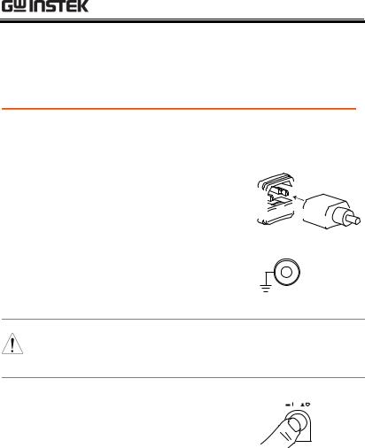
Steps |
1. |
Connect the power cord to |
|
|
the AC voltage input. |
|
2. |
If the power cord does not |
|
|
have an earth ground, |
|
|
ensure the ground |
terminal is connected to an earth ground.
GND
Ensure the power cord is connected to an earth Warning ground. Failure could be harmful to the operator
and instrument.
3. Press the Power button.
POWER
4.When the unit is powering up, all the LED indicators will light. Check to make sure all 5 LED indicators are working.
5.Check to make sure the System Self Test passes without errors.
18
|
|
|
|
|
|
GETTING STARTED |
||||||
|
|
|
|
|
|
|
|
|
|
|
|
|
|
|
|
|
|
|
|
|
|
|
|
|
|
|
|
|
|
|
|
|
|
|
|
|
||
|
|
S Y S T E M S |
E L F T E S T |
|
|
|
|
|
|
|
|
|
|
|
|
|
|
|
|
|
|
|
|
||
|
|
S y |
s t e m C h e c k i n g . . . |
|
|
T I M E R = 0 0 |
|
|||||
|
|
|
|
|
|
|
|
|
|
|
|
|
|
|
H a |
r d w a r e C h e c k i n g . . . |
|
|
T I M E R = 0 0 |
|
|||||
|
|
|
|
|
|
|
|
|
|
|
|
|
|
|
F i |
r m w a r e C h e c k i n g |
|
|
T I M E R = 0 0 |
|
|||||
|
|
|
|
|
|
|
|
|
|
|
|
|
|
|
|
|
|
|
|
|
T |
I M E R |
= 0 0 |
|
|
|
|
|
|
|
|
|
|
|
|
|
|
|
After the System Self Test completes, the tester will go into READY status and be ready to operate.
|
|
READY Status |
||||
|
|
|
|
|
|
|
H = 2 2 . 0 m A L = 0 . 0 0 m A |
|
|
|
T = 1 7 4 S |
||
1 00k V |
|
|
|
|
||
m A R |
E A D |
Y |
|
|||
A C W D C W I R |
|
M O D E T I M E |
||||
|
||||||
19

|
|
GPT-9600 Series User Manual |
|
|
|
|
|
|
|
|
|
|
Workplace Precautions |
|
|
|
Background |
The GPT-9600 Series are a high voltage |
|
|
|
instruments that output dangerous voltages. |
|
|
|
The following section describes precautions and |
|
|
|
procedures that must be followed to ensure a |
|
|
|
safe work environment. |
|
|
WARNING |
The GPT-96XX generates voltages in excess of |
|
|
5kVAC or 6kVDC. Follow all safety precautions, |
|
|
|
|
|
|
|
|
warnings and directions given in the following |
|
|
|
section when using the instrument. |
|
1. |
Only technically qualified personnel should be |
|
|
|
|
allowed to operate the safety tester. |
|
2. |
The operating workplace must be fully isolated, |
|
|
|
|
especially when the instrument is in operation. |
|
|
|
The instrument should be clearly labeled with |
|
|
|
appropriate warning signage. |
|
3. |
The operator should not wear any conductive |
|
|
|
|
materials, jewelry, badges, or other items, such |
|
|
|
wrist watches. |
|
4. |
The operator should wear insulation gloves for |
|
|
|
|
high voltage protection. |
|
5. |
Ensure the earth ground of the line voltage is |
|
|
|
|
properly grounded. |
|
6. |
Ensure any devices that are adversely affected |
|
|
|
|
by magnetic fields are not placed near the |
|
|
|
tester. |
|
20
|
GETTING STARTED |
|
|
|
|
Operating Precautions |
|
Background |
The GPT-9600 Series are high voltage |
|
instruments that output dangerous voltages. |
|
The following section describes precautions and |
procedures that must be followed to ensure that the testers are operated in a safe manner.
The GPT-96XX generates voltages of up to 5kVAC
WARNING |
or 6kVDC. Follow all safety precautions, warnings |
|
|
|
and directions given in the following section when |
|
using the instrument. |
1. |
Never touch the safety tester, lead wires, |
|
terminals, probes and other connected |
|
equipment when the tester is testing. |
2. |
Do not turn the safety tester on and off quickly |
|
or repeatedly. When turning the power off, |
|
please allow a few moments before turning the |
|
power back on. This will allow the protection |
|
circuits to properly initialize. |
|
Do not turn the power off when a test is |
|
running, unless in an emergency. |
3. |
Only use those test leads supplied with the |
|
instrument. Leads with inappropriate gauges |
|
can be dangerous to both the operator and the |
|
instrument. |
4. |
Do not short the HIGH VOLTAGE terminal |
|
with ground. Doing so could charge the chassis |
|
to dangerously high voltages. |
5. |
Ensure the earth ground of the line voltage is |
|
properly grounded. |
|
21 |

GPT-9600 Series User Manual
6.Only connect the test leads to the HIGH VOLTAGE terminals before the start of a test. Keep the test leads disconnected at all other times.
7.Always press the STOP button when pausing testing.
8.Do not leave the safety tester unattended. Always turn the power off when leaving the testing area.
9.When remotely controlling the safety tester, ensure adequate safety measures are in place to prevent:
Inadvertent output of the test voltage.
Accidental contact with the instrument during testing. Ensure that the instrument and DUT are fully isolated when the instrument is remotely controlled.
10.Ensure an adequate discharge time for the DUT.
When DCW or IR tests are performed, the DUT, test leads and probes become highly charged. The GPT-96XX has discharge circuitry to discharge the DUT after each test. The time required for a DUT to discharge depends on the DUT and test voltage.
Never disconnect the safety tester before a discharge is completed.
22

|
GETTING STARTED |
|
|
|
|
Basic Safety Checks |
|
Background |
The GPT-9600 Series are high voltage devices |
and as such, daily safety checks should be made to ensure safe operation.
1. Ensure all test leads are not broken and are free from defects such as cracks or splitting.
2. Ensure the safety tester is always connected to an earth ground.
3. Test the safety tester operation with a low voltage/current output:
Ensure the safety tester generates a FAIL judgment when the HIGH VOLTAGE and RETURN terminals are shorted (using the lowest voltage/current as the testing parameters).
Do not use high voltages/currents when the HIGH
WARNING |
VOLTAGE and RETURN terminals are shorted. It |
|
|
|
may result in damage to the instrument. |
23
 Loading...