


AUTOMATIC GATE OPERATOR
FOR VEHICULAR SLIDE GATES
INSTALLATION MANUAL FOR THE PROFESSIONAL INSTALLER
 WARNING!
This equipment is similar to other gate or door equipment and meets or exceeds Underwriters Laboratory Standard 325 (UL 325). However, gate equipment has hazards associated with its use and therefore by installing this product the installer and user accept full responsibility for following and noting the installation and safety instructions. Failure to follow installation and safety instructions can result in hazards developing due to improper assembly. You agree to properly install this product and that if you fail to do so GTO, Inc. shall in no event be liable for direct, indirect, incidental, special or consequential damages or loss of profits whether based in contract tort or any other legal theory during the course of the warranty or at any time thereafter. The installer and/or user agree to assume responsibility for all liability and use of this product releasing GTO, Inc. from any and all liability. If you are not in agreement with this disclaimer or do not feel capable of properly following all installation and safety instructions you may return this product for full replacement value.
READALLINSTRUCTIONSCAREFULLYANDCOMPLETELYbeforeattempting toinstallandusethisautomaticgateopener. Thisgateopenerproducesahighlevelof force. Stay clear of the unit while it is operating and exercise caution at all times.
All automatic gate openers are intended for use on vehicular gates only.
This product meets and exceeds the requirements of UL 325, the standard which regulates gate opener safety, as established and made effective March 1, 2000, by Underwriters Laboratories Inc.
DO NOT INSTALL THIS OPERATOR WITHOUT SAFETY EDGES AND ROLLER GUARDS!
|
3121 Hartsfield Road • Tallahassee, Florida, USA 32303 |
|
Telephone GTO Sales: 1-800-543-GATE (4283) or (850) 575-0176 • Fax (850) 575-8912 |
|
or GTO Technical Service: 1-800-543-1236 or (850) 575-4144 • Fax (850)575-8950 |
RB270 rev - 4/5/06 |
www.gtoinc.com |
TABLE OF CONTENTS
Gate Operator Class Categories -------------------------------------------------------- |
inside cover |
Important Safety Instructions ----------------------------------------------------------- |
page 1 |
Important Safety Instructions for the System Designer ---------------------------- |
page 2 |
Important Safety Instructions for the Installer --------------------------------------- |
page 2 |
Secondary means of Protection Against Entrapment ------------------------------- |
page 4 |
Important Safety Instructions for the Consumer/End User ------------------------ |
page 5 |
Warning Labels and Signs -------------------------------------------------------------- |
page 7 |
Technical Specifications for SL-1000 ---------------------------------------------------- |
page 9 |
Technical Specifications for SL-2000 ---------------------------------------------------- |
page 10 |
Parts Identification (Single Gate Operator) ------------------------------------------- |
page 11 |
Single Gate Operator Installation ------------------------------------------------------- |
page 12 |
Overview and Gate Preparation ------------------------------------------------------- |
page 12 |
Suggested Conduit & Wiring and Mounting the Legs ------------------------------ |
page 13 |
Determining the Mounting Position and Mounting the Operator ----------------- |
page 14 |
Installing the Chain ---------------------------------------------------------------------- |
page 15 |
Disconnecting Operator Chain for Manual Operation of Gate -------------------- |
page 15 |
Powering the System ----------------------------------------------------------------------- |
page 16 |
Maximum Operational Cycles Chart -------------------------------------------------- |
page 16 |
Installation of the Transformer --------------------------------------------------------- |
page 16 |
Control Board settings --------------------------------------------------------------------- |
page 20 |
DIP Switches ---------------------------------------------------------------------------------- |
page 20 |
Potentiometers -------------------------------------------------------------------------------- |
page 21 |
Connecting the Receiver to the Control Board --------------------------------------- |
page 22 |
SettingYour Personal Transmitter Code -------------------------------------------------- |
page 22 |
Mounting the Receiver ---------------------------------------------------------------------- |
page 23 |
Adjusting the Limit Switches ------------------------------------------------------------ |
page 24 |
Connecting Safety Devices ---------------------------------------------------------------- |
page 25 |
Connecting Accessories--------------------------------------------------------------------- |
page 26 |
Maintenance --------------------------------------------------------------------------------- |
page 28 |
Troubleshooting Guide--------------------------------------------------------------------- |
page 29 |
Warranty and Repair Information ------------------------------------------------------ |
page 31 |
Dual Gate System Installation ----------------------------------------------------------- |
page 32 |
Preparing the Gates ---------------------------------------------------------------------- |
page 34 |
Wiring the Second Operator ----------------------------------------------------------- |
page 35 |
Setting the Control Board for Dual Gate Installations ----------------------------- |
page 36 |
Accessory Catalog ------------------------------------------------------------------------- |
page 38 |
Installation Check List ------------------------------------------------------- |
inside back cover |
IMPORTANT SAFETY INSTRUCTIONS
FOR THE GTO/PRO SL-1000/2000 AND GTO/PRO SL-1000B/2000B
AUTOMATIC SLIDE GATE OPERATORS
Because automatic gate operators produce high levels of force, all system designers, installers, and consumers have an obligation to know the potential hazards associated with improperly designed, installed, or maintained gate operator systems. Keep in mind that the gate operator is just one component of the total gate operating system.
Each component must work in unison to provide the consumer with convenience, security, and safety.
This manual contains various safety precautions and warnings for the system designer, installer, and consumer. Because there are many possible applications of the gate operator, the safety precautions and warnings contained in this manual cannot be completely exhaustive in nature. They do, however, provide an overview of the safe design, installation, and use of this product. CAREFULLY READ AND FOLLOW ALL SAFETY PRECAUTIONS,
WARNINGS, AND INSTALLATION INSTRUCTIONS TO ENSURE THE SAFE SYSTEM DESIGN, INSTALLATION, AND USE OF THIS PRODUCT.
The precautions and warnings in this manual are identified with this  warning symbol.
The  symbol identifies the conditions that can result in damage to the operator or its components, serious injury, or death.
Because GTO automatic gate operators are only part of a total gate operating system, it is the responsibility of the designer, installer, and purchaser to ensure the total system is safe for its intended use. Bypassing safety devices or neglecting to use safety devices with the gate operator is NOT acceptable.
TO MANUALLY OPEN AND CLOSE THE GATE, FOLLOW THE PROCEDURE BELOW:
 CAUTION: Disconnect the operator chain ONLY when the gate is NOT moving.
1.Lift the quick release pins UP, then pull them OUT of the chain brackets (see illustration).
2.Lay the chain down and manually slide the gate to the desired position.
To prevent unauthorized removal of the quick release pins, install pin locks (see accessory catalog) above the quick release pins in both chain brackets.
Chain Bracket (204IH)
Quick Release Pin (211IH)
1

IMPORTANT SAFETY INSTRUCTIONS
FOR THE SYSTEM DESIGNER
WARNING: To reduce the risk of injury or death:
1.READ AND FOLLOW ALL INSTRUCTIONS.
2.This operator is intended for use only on vehicular gates. Pedestrians must be supplied with a separate walk-through gate (see Entrapment Protection on page 6).
3.When designing a system that will be entered from a highway or main thoroughfare, make sure the system is placed far enough from the road to prevent traffic congestion.
FOR THE INSTALLER
WARNING-To reduce the risk of injury or death:
I.Before Installation
1.READ AND FOLLOW ALL INSTRUCTIONS.
2.Verify this operator is proper for the type and size of gate, and its frequency of use.
3.Make sure the gate has been properly installed and slides freely in both directions. Repair or replace all worn or damaged gate hardware prior to installation. A freely moving gate will require less force to operate and will enhance the performance of the operator and safety devices used with the system.
4.All openings of a horizontal slide gate must be guarded or screened to prevent a 21/4 inch diameter sphere from passing through openings anywhere in the gate. This screen (or guard) must also be installed over the portion of adjacent fence that the gate covers in the open position (see page 6).
5.Review the operation of the system and become familiar with its safety features. Understand how to disconnect the operator chain with the quick release pins for manual operation of the gate (see page 1).
6.This gate operator is intended for vehicular gates ONLY. A separate entrance or gate must be installed for pedestrian use (see page 6). NO ONE SHOULD CROSS THE PATH OF A MOVING GATE.
II.During Installation
1.Install the gate operator on the inside of the property and fence line. DO NOT install an operator on the outside of the gate where the public has access to it.
2.Be careful with moving parts and avoid close proximity to areas where fingers or hands could be pinched.
3.Determine the best obstruction sensing setting for this installation. The gate MUST stop and reverse on contact with an obstruction or when an object activates the non-contact sensors. After adjusting the force or the limit of travel, retest the gate operator. Failure to adjust and retest the gate operator properly increases the risk of injury or death.
4.Additional safety equipment such as roller guards and safety edges (or photoelectric sensors) MUST be installed to prevent bodily injury (see page 6).
2

IMPORTANT SAFETY INSTRUCTIONS
5.Mount access controls away from the gate (minimum distance is 10 feet). The user must have full view of the gate but be unable to touch it while operating the controls.
6.Secure outdoor or easily accessed gate operator controls in order to prohibit unauthorized use of the gate.
III.After Installation
1.Review ALL safety instructions with the consumer/end user and explain the basic operation and safety systems of the entire gate operator system, including disconnecting the chain for manual gate operation.
2.Inform the consumer/end user that servicing of the operator must only be done by an experienced technician.
3.Attach the warning signs (included) to each side of the gate to alert public of automatic gate operation. Take a photo of warning signs installed on gate. Record the date of the photo for your reference.
4.SAVE THESE INSTRUCTIONS. Leave IMPORTANT SAFETY INSTRUCTIONS
(included) with consumer/end user.
3
IMPORTANT SAFETY INSTRUCTIONS
SECONDARY MEANS OF PROTECTION AGAINST ENTRAPMENT
As specified by Underwriters Laboratories Inc. UL 325 (31.1.1), automatic gate operators shall have provisions for, or be supplied with, at least one independent primary and one independent secondary means to protect against entrapment. GTO gate operators utilize Type A, an inherent entrapment sensing system, as the primary type of entrapmentprotection. TheGTO/PROSL-1000/2000andGTO/PROSL-1000B/2000Bgateoperatorshaveprovisions for the connection of Type B1 and B2 protection to be used as the secondary type of entrapment protection.
1.For gate operators utilizing a non-contact sensor (Type B1) in accordance with UL 325 (31.1.6):
A.Refer to the sensor manufacturer’s instructions on the placement of non-contact sensors for each type of application.
B.Care shall be exercised to reduce the risk of nuisance tripping, such as when a vehicle trips the sensor while the gate is still moving.
C.One or more non-contact sensors shall be located where the risk of entrapment or obstruction exists, such as the perimeter reachable by a moving gate or barrier.
2.For gate operators utilizing a contact sensor (Type B2) in accordance with UL 325 (31.1.10):
A.One or more contact sensors shall be located at the leading edge, trailing edge, and post mounted edge, both inside and outside of a vehicular slide gate system.
B.A hard wired contact sensor shall be located and its wiring arranged so that the communication between the sensor and the gate operator is not subjected to mechanical damage.
C.A wireless contact sensor such as one that transmits radio frequency (RF) signals to the gate operator for entrapment protection functions shall be located where the transmission of the signals are not obstructed or impeded by building structures, natural landscaping or similar obstruction. A wireless contact sensor shall function under the intended end-use conditions.
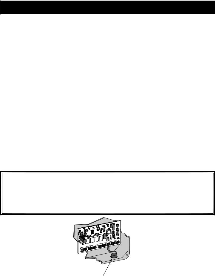
ENTRAPMENT ALARM (UL 325; 31.2.1)
The GTO/PRO SL-2000 and GTO/PRO SL-2000B operators are designed to stop and reverse for 2 seconds when the gate comes in contact with an obstruction or when an object activates the non-contact sensors. Additionally, these operators are equipped with an audio entrapment alarm which will function if the unit obstructs twice while opening or closing. This alarm will sound for a period of 5 minutes or until the operator receives an intended signal (e.g., transmitter signal) and the gate returns to a fully open or fully closed position.
+
BATT
–
PWR. |
SW. |
AUTO |
|
CLOSE |
|
STATUS |
|
INERTI |
A |
OBSTR |
. |
SENS. |
|
18V |
AC |
SOL |
AR |
ED LK ORG LU GRN LS OPN |
||
+ |
|
|
|
|||
~ |
~ |
|
|
|
|
|
|
|
|
|
FIRST |
OPER |
ATOR |
|
|
|
|
|
||
POWE |
R IN |
|
|
|
|
|
|
|
EDG |
N RG LU WHT |
|
ED LK ORG LU GRN LS OPN |
|
|||
|
|
|
|
SORY |
|
|
ERATO |
R |
AL |
|
ND OP |
|
||
SECO |
|
|
||
|
|
|
||
|
|
|
|
|
LEARN
R |
G |
B |
RCVR
Entrapment Alarm (bottom right of control box)
4

IMPORTANT SAFETY INSTRUCTIONS
FOR THE CONSUMER/END USER
WARNING: To reduce the risk of injury or death:
1.READ AND FOLLOW ALL INSTRUCTIONS.
2.Distribute and discuss copies of the IMPORTANT SAFETY INSTRUCTIONS manual with all persons authorized to use your gate. SAVE THESE INSTRUCTIONS.
3.Always keep people and objects away from the gate and its area of travel.
NO ONE SHOULD CROSS THE PATH OF THE MOVING GATE.
4.Yourautomaticgateisnotforpedestrianuse. Ifpedestriantrafficisexpectednearthegate,awalk-through gate must be installed for this purpose (see page 6).
5.Do not allow children or pets near your gate. Never let children operate or play with gate controls.
Keep the remote controls away from children and unauthorized users; store controls where children and unauthorized users cannot access them.
6.If push buttons or key switches are installed, they should be within sight of the gate, yet located far enough from the gate (at least 10 feet) so the gate cannot be touched while in operation. Do not operate any control without watching the movement of the gate.
7.Do not activate your gate operator unless you can see it and can determine that its area of travel is clear of people, pets, or other obstructions.
8.If your gate has open rollers, be sure that roller guards have been installed to prevent hands and fingers from being caught in the rollers (see page 6).
9.It is your responsibility to make sure that the installer posted warning signs on both sides of your gate. If any of these signs or warning decals become damaged, illegible or missing, replace them immediately. Contact your installer or GTO for replacements.
10.Verify that electric safety edge sensors (or photoelectric sensors) have been installed (see page 6). These safety devices should be tested monthly.
11.KEEP GATES PROPERLY MAINTAINED. Have a qualified service person make repairs to the gate hardware. NEVER REMOVE THE OPERATOR HOUSING.
12.DO NOT attempt to service this operator yourself; for service, contact your installer or another experienced technician.
13.Haveyourgateoperatortestedmonthlyandservicedregularlybyanexperiencedtechnician.ThegateMUST stop and reverse on contact with an obstruction or when an object activates the non-contact sensors. If these functions are observed to operate improperly, discontinue use and have operator serviced immediately.
14.To operate this equipment safely, YOU must receive detailed instructions on disconnecting the operator chain with the quick release pins (see page 1). If you feel you have not received full and proper instructions, contact your installer.
15.Disconnect the operator chain ONLY when the gate is NOT moving and turned off.
5

IMPORTANT SAFETY INSTRUCTIONS
REQUIRED SAFETY PRECAUTIONS FOR GATES
INSTALL SCREEN GUARD OVER GATE AND FENCE
Injuries may occur when people place their hands, arms, legs, etc., through openings in the gate grill when the gate is operated, trapping them between the grill and the fence post (or fence). All openings of a horizontal slide gate must be guarded or screened to prevent a 21/4” diameter sphere from passing through openings anywhere in the gate. This screen/guard must also be installed over the portion of adjacent fence that the gate covers in the open position. Screening will prevent access through openings in areas where the gate may travel.
Contact Sensor |
Screen Mesh |
Contact Sensor |
Contact Sensor |
||||||||||||
|
|
|
|
|
|
|
|
|
|
|
|
|
|
|
|
|
|
|
|
|
|
|
|
|
|
|
|
|
|
|
|
|
|
|
|
|
|
|
|
|
|
|
|
|
|
|
|
|
|
|
|
|
|
|
|
|
|
|
|
|
|
|
|
Roller guard to prevent |
ROLLER GUARDS |
pinch point hazard. |
Injuries occur |
Contact Sensor |
when people get |
their hands caught |
|
|
between the gate |
|
and the roller. |
|
Roller guards or |
|
enclosed tracks |
|
must be installed to |
|
prevent this pinch |
|
point hazard. |
|
Roller guard to prevent |
|
pinch point hazard. |
! WARNING
Moving Gate Can Cause
Injury Or Death
1. KEEP CLEAR! Gate may move at any time.
2. Do not allow children to operate gate or play in gate area.
3. This gate is for vehicles only. Pedestrians must use a separate entrance.
WARNING SIGNS
The warning signs (above right) must be installed on both sides of the gate (see page 7 for details).
ENTRAPMENT PROTECTION
GTO’s internal obstruction settings, even when properly adjusted, may not be sensitive enough to prevent bodily injury. For this reason, safety devices such as safety edges MUST be installed. Furthermore, a pedestrian gate must be installed if walk-through traffic is expected near the gate. We recommend the GTO Bulldog Pedestrian Gate Lock (see accessory catalog) for controlled access.
Pedestrian Gate |
Contact Sensor |
Contact Sensor |
Roller Guard |
Warning Sign |
|
||
|
|
|
|
|
|
! WARNING |
|
|
|
Moving Gate Can Cause |
|
|
|
Injury Or Death |
|
|
|
|
CAUTION |
|
|
Vehicle Gate |
|
|
|
|
Operator |
Roller Guard
6
IMPORTANT SAFETY INSTRUCTIONS
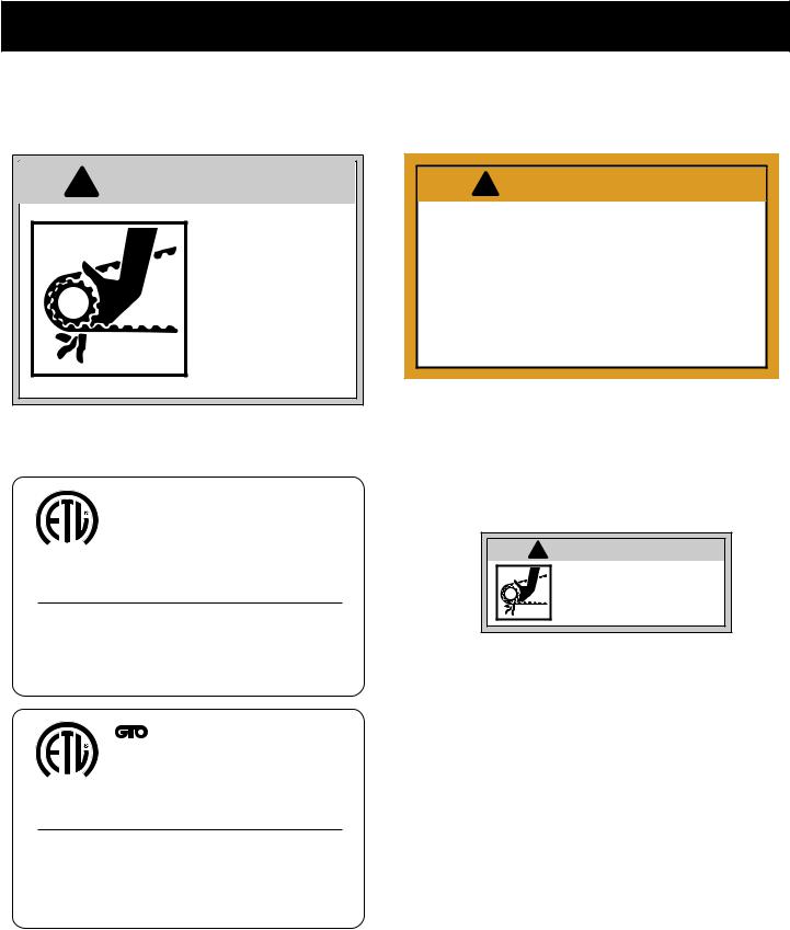
These warning labels should be found at the locations specified below. If any of them are missing, immediately contact your installer for replacements.
!WARNING
•Fingers, hands, and loose clothing may be dragged into chain sprockets.
•Fingers and hands can
be injured by rotating sprockets.
• Keep hands, fingers, and loose clothing away from chain and chain opening in operator housing.
warning labels (3). Located on both sides and back of operator housing

 SL
SL


 Series
Conforms to UL 325 STANDARDS
CUS Certified to CAN/CSA-C22.2 No.247-92
D |
Maximum Gate: 500 lb. (226.7 kg); 30 ft. (9.1 m) |
ISTE |
|
9901178 |
Voltage: 12 Vdc; Frequency: 0 Hz; Power: 93.2 W |
|
Class I, II and III Vehicular Slide Gate Operator |
|
Serial Number: SL1000-xxxxxxx |
Disconnect operator ONLY when the gate is NOT moving.
TO MANUALLY OPEN AND CLOSE THE GATE:
1.Lift quick release pins UP, then pull them OUT of chain brackets.
2.Lay chain down and manually slide gate to desired position.
GTO, Inc. Tallahassee, Florida USA |
RB2001 |


 Series
Conforms to UL 325 STANDARDS
Certified to CAN/CSA-C22.2 No.247-92
CUS
I |
STE |
Maximum Gate: 1000 lb. (453.4 kg); 30 ft. (9.1 m) |
D |
|
|
9901178 |
Voltage: 12 Vdc; Frequency: 0 Hz; Power: 93.2 W |
|
Class I, II and III Vehicular Slide Gate Operator
Serial Number: SL2000-xxxxxxx
Disconnect operator ONLY when the gate is NOT moving.
TO MANUALLY OPEN AND CLOSE THE GATE:
1.Lift quick release pins UP, then pull them OUT of chain brackets.
2.Lay chain down and manually slide gate to desired position.
GTO, Inc. Tallahassee, Florida USA |
RB2002 |
!WARNING
•Moving parts inside are capable of causing injury to fingers and hands.
•DO NOT remove operator housing.
•Consult your safety manual before making adjustments.
•For service, call an experienced technician.
 AUTOMATIC GATE OPENERS 1-800-543-GATE
warning label located on front of operator housing
! WARNING
may be dragged into chain sprockets.
• Fingers and hands can be injured by rotating sprockets.
• Keep hands, fingers, and loose clothing away from chain and sprockets.
warning label located on top of control box
product identification and manual operation instruction label installed on control box cover
7
IMPORTANT SAFETY INSTRUCTIONS
Continued from page 7
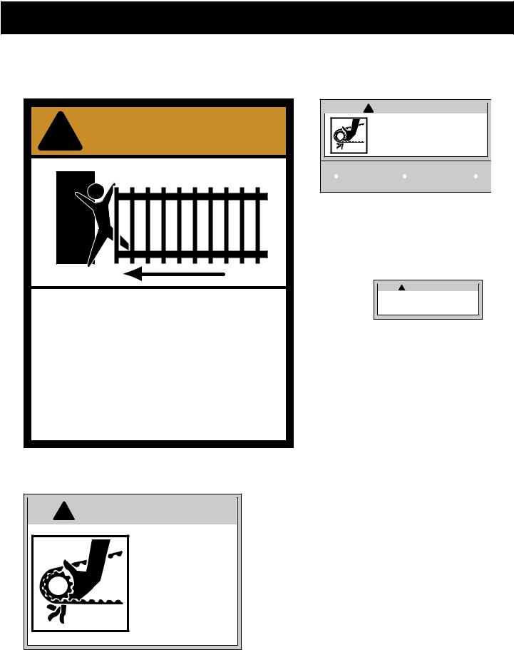
These warning labels should be found at the locations specified below. If any of them are missing, immediately contact your installer for replacements.
! WARNING
! WARNING
• Fingers, hands, and loose clothing may be dragged into chain sprockets.
• Fingers and hands can be injured by rotating sprockets.
• Keep hands, fingers, and loose clothing away from chain and sprockets.
Moving Gate Can Cause
Injury Or Death
1.KEEP CLEAR! Gate may move at any time.
2.Do not allow children to operate gate or play in gate area.
3.This gate is for vehicles only. Pedestrians must use a separate entrance.
warning signs (2) to be installed on each side of the gate (3–5 feet above the bottom of the gate)
! WARNING
warning sign located (inside housing) over the top sprocket at back of operator
!WARNING
•Adjusting limit switches with power on will activate gate.
•Injury may result if fingers get caught under switch plate while adjusting switches.
•Use extreme caution when adjusting switches.
warning label located on limit switch plate
• Fingers, hands, and loose clothing may be dragged into chain sprockets.
• Fingers and hands can be injured by rotating sprockets.
• Keep hands, fingers, and loose clothing away from chain and sprockets.
warning label located (inside housing) next to sprockets on back of operator
8
GTO PRO SL-1000 SERIES TECHNICAL SPECIFICATIONS
DRIVE
•Powered by a 12 V motor with integral case hardened steel gear reduction to 90 rpm. Generates 155 in. lb. of torque at 12 V. Motor temperature range -30 °F to +160 °F.
•Gate velocity: 1 ft/s.
POWER
•The PRO SL-1000 system is powered by a 12Vdc, 7.0Ah, sealed, rechargeable battery.
•Battery charge for PRO SL-1000 is maintained by a 18Vac (40VA) transformer rectified to 14.5Vdc through the GTO Control Board. Two (2) blade-style control board fuses rated for 15A.
NOTE: The transformer should not be connected directly to any battery.Transformer must be connected with a minimum of 16 gauge, multi-stranded, dual conductor, direct burial low voltage wire. NOTE: Do not replace fuses with higher ampere rated fuses; doing so will void the warranty and may damage the control board.
•Battery charge maintained by GTO Solar Panel Charger: float voltage 14.5Vdc output from a
193/8” x 151/4” silicon alloy panel. Generates minimum of 10 W at 600 mA. Gated diode on the control board prevents battery discharge.
CONTROL
•GTO microprocessor controlled board with temperature compensated circuits. Auto-memorization of digital transmitter code. Charging regulated by circuit on control board. “Sleep draw” is 40 mA; “active draw” is 2 to 5A.
•GTO remote-mounted RF receiver tuned to 318 MHz.
•Limit controls are mechanical. Normally open contact.
•Adjustable auto-close timer (OFF to 120 s), inertia, and obstruction sensitivity using three (3) potentiometers.
•Power terminal block accommodates a transformer and solar panels.
•Operator terminal blocks accommodate safety edges and photoelectric sensors for opening and closing modes.
•Fully compatible accessory terminal block provides connections for safety loops, wands, intercoms, card readers, phone systems, etc.
•DIP switches simplify setup of gate operator.
•audio entrapment alarm sounds if unit obstructs twice while opening or closing.
OPERATIONAL CAPACITY
•The GTO/PRO SL-1000 and GTO/PRO SL-1000B will handle gates weighing up to 500 lb. (226.7 kg) and up to 30 ft. (9.14 m) in length (per leaf) if the proper installation procedures have been followed. Note that ball bearing rollers and covers should be used on all gates.
•The GTO/PRO SL-1000 series operators are capable high volume cycling; however, the total cycles per day will depend on the motor current and efficiency of the gate installation (see chart below). For questions relating to specific applications and for information regarding cycling duty when charged by solar panels, call the GTO Service Department at (800) 5431236.
Gate Capacity Chart for SL-1000 Series
(estimated number of cycles based on use with a transformer)
Gate Opening
20 ft. |
120 |
110 |
|
100 |
90 |
16 ft. |
140 |
130 |
|
120 |
110 |
12 ft. |
160 |
150 |
|
140 |
130 |
8 ft. |
180 |
170 |
|
160 |
150 |
|
200 lb. |
300 lb. |
400 lb. |
500 lb. |
|
|
Gate Weight |
|
|
||
Cycles shown are for single gate, dual gates will get approximately half as many cycles.
Housing Dimensions: |
Height: 18” Width: 211/2” Depth: 11” |
Shipping Weight: |
Approximately 90 lb. |
|
|
Rollers should be lubricated at least four times per year. SPECIFICATIONS SUBJECT TO CHANGE WITHOUT NOTICE.
9
GTO PRO SL-2000 SERIES TECHNICAL SPECIFICATIONS
DRIVE
•Powered by a 12 V motor with integral case hardened steel gear reduction to 90 rpm. Generates 310 in. lb. of torque at 12 V. Motor temperature range -30 °F to +160 °F.
•Gate velocity: 1 ft/s.
POWER
•The PRO SL-2000 system is powered by a 12Vdc, 7.0Ah, sealed, rechargeable battery.
•Battery charge for PRO SL-2000 is maintained by a 18Vac (40VA) transformer rectified to 14.5Vdc through the GTO Control Board. Two (2) blade-style control board fuses rated for 20A.
IMPORTANT: The transformer should not be connected directly to any battery.Transformer must be connected to the control board with a minimum of 16 gauge, multi-stranded, dual conductor, direct burial low voltage wire. Do not replace fuses with higher ampere rated fuses; doing so will void the warranty and may damage the control board.
•Solar Panel Charger can only be used on the SL-2000 if the optional 24Amp hour battery kit is used (seeAccessory Catalog on page 41). Battery charge maintained by GTO Solar Panel Charger: float voltage 14.5Vdc output from a 193/8” x 151/4”
silicon alloy panel. Generates minimum of 10 W at 600 mA. Gated diode on the control board prevents battery discharge.
CONTROL
•GTO microprocessor controlled board with temperature compensated circuits. Auto-memorization of digital transmitter code. Charging regulated by circuit on control board. “Sleep draw” is 40 mA; “active draw” is 5 to 13A.
•GTO remote-mounted RF receiver tuned to 318 MHz.
•Limit controls are mechanical. Normally open contact.
•Adjustable auto-close timer (OFF to 120 s), inertia, and obstruction sensitivity using three (3) potentiometers.
•Power terminal block accommodates a transformer and solar panels.
•Operator terminal blocks accommodate safety edges and photoelectric sensors for opening and closing modes.
•Fully compatible accessory terminal block provides connections for safety loops, wands, intercoms, card readers, phone systems, etc.
•DIP switches simplify setup of gate operator.
•audio entrapment alarm sounds if unit obstructs twice while opening or closing.
OPERATIONAL CAPACITY
•The GTO/PRO SL-2000 and GTO/PRO SL-2000B will handle gates weighing up to 1000 lb. (453.4 kg) and up to 30 ft. (9.14 m) in length (per leaf) if the proper installation procedures have been followed. Note that ball bearing rollers and covers should be used on all gates.
•The GTO/PRO SL-2000 series operators are capable of high volume cycling; however, the total cycles per day will depend on the motor current and efficiency of the gate installation (see chart below). For questions relating to specific applications and for information regarding cycling duty when charged by solar panels, call the GTO Service Department at (800) 5431236.
Gate Capacity Chart for SL-2000 Series
(estimated number of cycles based on use with a transformer)
Opening |
20 ft. |
80 |
70 |
60 |
50 |
|
16 ft. |
100 |
90 |
80 |
70 |
||
|
||||||
|
12 ft. |
120 |
110 |
100 |
90 |
|
Gate |
8 ft. |
140 |
130 |
120 |
110 |
|
|
400 lb. |
600 lb. |
800 lb. |
1000 lb. |
Gate Weight
Cycles shown are for single gate, dual gates will get approximately half as many cycles.
Housing Dimensions: |
Height: 18” Width: 211/2” Depth: 11” |
Shipping Weight: |
Approximately 90 lb. |
|
|
Rollers should be lubricated at least four times per year.
SPECIFICATIONS SUBJECT TO CHANGE WITHOUT NOTICE.
10
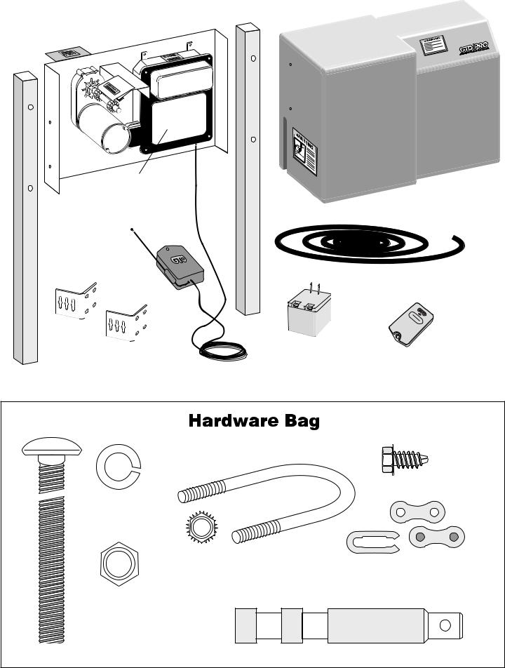
PARTS IDENTIFICATION 
Operator
Control Box with |
Operator Housing |
|
Control Board |
||
(A207) |
||
and Battery |
||
|
||
Receiver |
|
|
(AQ202) |
|
|
|
32’ Drive Chain |
|
|
(RB207) |
(2) Chain Brackets (204IH) |
18 Vac Transformer |
GTO Transmitter |
|
120 Volt (RB570) |
|
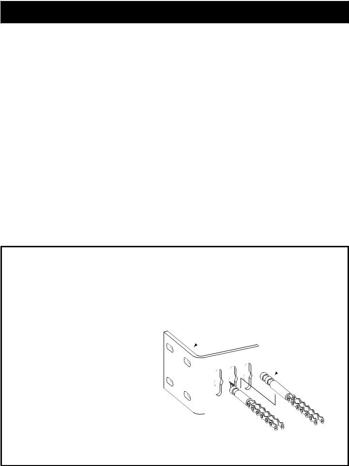
(2) 2” square x 48” long legs (206IH) |
|
(RB740) |
|
|
 (4) 3/8” Lock Washers
(RB641)
(4) 3/8”-16 x 2” diameter U-Bolts and (8) 3/8”Serrated Nuts (RB210)
(4) 3/8” Nuts
(RB668)
(4) 1/4”-20 x 1/2” Screws
(RB226)
(2) Chain Master Links
(RB208)
(4) 3/8” -16 x 3” Carriage Bolts (RB659) |
(2) Quick Release Pins (211IH) |
11
 Loading...