


®
, Inc.
TM
PEDESTRIAN GATE LOCK
Installation Manual
PLEASE NOTE ... due to the variety of possible mounting applications, no mounting hardware for the lock is provided. All necessary mounting hardware can be obtained at a local hardware store; all other hardware is provided. If you need assistance please call GTO® Technical Service at 800-543-1236.
Contents
• Before You Start ----------------------------------- |
page 1 |
• Parts Identification -------------------------------- |
page 2 |
• Mounting the Lock -------------------------------- |
page 3 |
• Wiring the Control Board ------------------------- |
page 6 |
• Accessory and Warranty Information ----------- |
inside back cover |
RB920 … rev- 5/20/03

Before You Start ...
Materials you will need before you begin the installation.
•For all installations use mounting hardware (not included) no greater than 5/16” diameter. Note: for a more secure installation, we suggest you use lock washers and/or lock nuts on all mounting hardware.
•For most IRON and ALUMINUM TUBE gates (see Illustration C, page 4) use bolts, washers, and nuts to mount both the lock and the receiver.
•For most CHAIN LINK gates (see Illustration D, page 4) use U-Bolts and saddles to mount the lock, and use bolts, washers, and nuts to mount the receiver.
•Use up to 500 ft. of 16 gauge, multi-stranded, direct burial, low voltage wire (see inside back cover) to connect the control box battery to the DC charger. Length depends on distance between the power supply and the control box. Ten (10) ft. of wire is included to connect the control board to the entry control; i.e. push button or keypad.
Other materials you may need before you begin the installation:
•If AC power source is more than 500 ft. from lock installation, or if installing lock where AC power is not preferred (i.e. swimming pool gate), use the GTO/PRO® 5 Watt Solar Panel to provide battery charge (see inside back cover).
•If mounting Bulldog lock on brick columns, walls, or other applications with limited space between gate and post use the Column Mount Lock Receiver (see inside back cover).
•Use PVC conduit for protection of low voltage wire connecting the control box to battery charger and entry control (see Illustration A, page 3).
•The push button is included with your Bulldog Gate Lock for entry control. However, other devices (card readers, keypads) with normally open (n/o) contacts may be used. Transmitters are not compatible with this product.
•For greater security, use the GTO Digital Keypad for entry control (see inside back cover). We strongly recommend using the Digital Keypad on swimming pool and daycare gates to help prevent children from activating lock release.
The installation has two parts ...
•Mounting The Lock and Control Box
•Wiring The Control Board
Once you have the necessary wire and mounting hardware, you are ready to begin the installation.
1
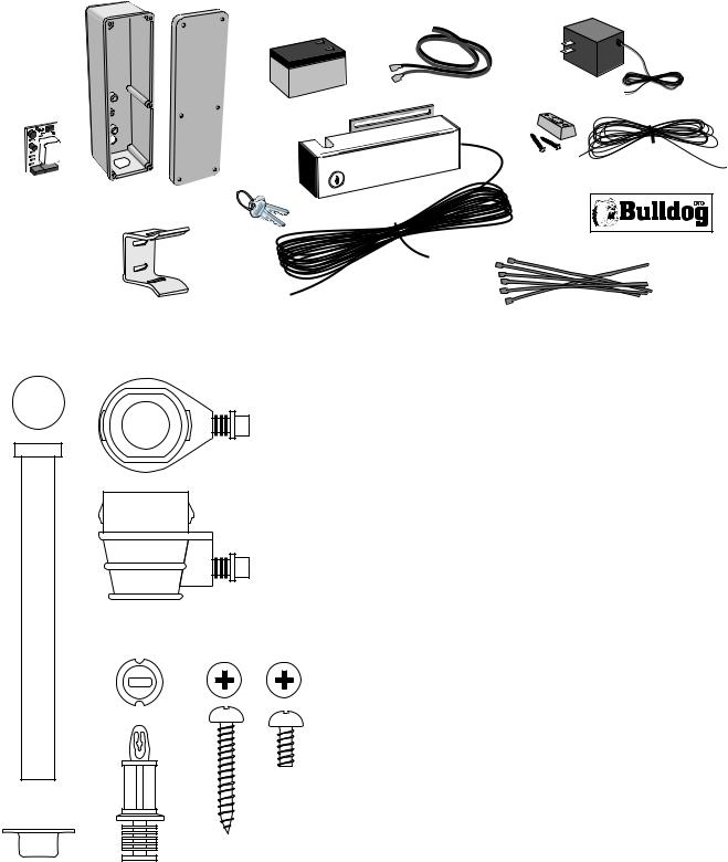
Parts Identification
K  H
H
G
J
|
|
|
I |
F |
E |
A |
|
|
|
, Inc. |
|
|
|
L |
Q |
|
|
AUTOMATIC SOLENOID |
|
|
|
SECURITY GATE LOCK |
B
R
|
|
A - Lock w/ 20' of Low Voltage Wire |
|
|
B - Lock Receiver |
|
|
C - Clevis Pin |
|
P (top) |
D - Locking Cap |
|
E - Control Box |
|
|
|
|
|
|
F - Lock Control Board |
|
|
G -12 Volt DC Charger |
|
|
H -Battery Lead Wires |
|
|
I - Ten (10) ft. of Low Voltage Wire to connect Entry |
|
|
Device (push button or keypad) to Control Board |
|
P (side) |
J - Push Button Entry Control and mounting screws |
|
K -12 Volt Battery / 1.2 Amp Hour |
|
|
|
|
|
|
L - Manual Release Keys |
|
|
M - (6) Control Box Cover Screws |
|
|
N - (2) Control Box Mounting Screws |
|
O (top) |
O - (2) Control Board Mounting Stand-offs |
|
|
P - Strain Relief |
|
|
Q - Bulldog Lock Decal (place on lock face after |
C |
M |
installation) |
|
R - (6) 8" Ty-wraps |
|
|
N |
|
D |
O (side) |
|
2
 Loading...