


 Loading...
Grundig DAVIO 37, DAVIO 55, P 37-2201, P 37-4201 TOP, T 51-4201 TOP Service Manual [en, de]
...TV |
|
|
|
|
|
Service Manual |
|||
Zusätzlich erforderliche Unterlagen für den Komplettservice Additionally required Service Documents for the Complete Service
Service |
|
Service |
Manual |
|
Training |
Sicherheit |
|
Chassis 12.5 |
Safety |
|
|
Materialnr./Part No. |
|
Materialnr./Part No. |
720108000000 |
|
720103507000 |
Materialnummer/Part Number 720100433000
Änderungen vorbehalten/Subject to alteration • Printed in Germany FD H-S43 0302 • 8002/8012, 8003/8013
http://www.grundig.com
Chassis 12.5
DAVIO 37
P 37-2201
GBA0700
DAVIO 37
P 37-4201 TOP
GBA0800
GBA0801
DAVIO 37
P 37-4201/5 TOP
GBA1100
DAVIO 51
T 51-4201 TOP
GBA0900
GBA0901
DAVIO 51
T 51-4201/5 TOP
GBA1200
DAVIO 55
T 55-4201 TOP
GBA1000
GBA1001
DAVIO 55
T 55-4201/5 TOP
GBA1300
Grundig Service
|
Hotline Deutschland… |
|
…Mo.-Fr. 8.00-18.00 Uhr |
||
Technik: |
|
|
TV |
0180/52318-41 |
|
TV |
0180/52318-49 |
|
SAT |
0180/52318-48 |
|
VCR/LiveCam |
0180/52318-42 |
|
HiFi/Audio |
0180/52318-43 |
|
Car Audio |
0180/52318-44 |
|
Telekommunikation |
0180/52318-45 |
|
Fax: |
0180/52318-51 |
|
Planatron (8.00-22.00 Uhr) 0180/52318-99 |
||
Ersatzteil-Verkauf: |
Mo.-Fr. 8.00-19.00 Uhr |
|
Telefon: |
0180/52318-40 |
|
Fax: |
0180/52318-50 |
|
Kundendienst/Werkstätten: Mo.-Fr. 8.00-18.00 Uhr |
||
Telefon: |
0180/52318-52 |
|
Fax: |
0180/52318-46 |
|
gebührenpflichtig
Allgemeiner Teil / General Section |
Chassis 12.5 |
Es gelten die Vorschriften und Sicherheitshinweise gemäß dem Service Manual "Sicherheit", Materialnummer 720108000000, sowie zusätzlich die eventuell abweichenden, landesspezifischen Vorschriften!
The regulations and safety instructions shall be valid as provided by the "Safety" Service Manual, part number 720108000000, as well as the respective national deviations.
D |
|
GB |
|
Inhaltsverzeichnis |
|
Table of Contents |
|
|
Seite |
|
Page |
Allgemeiner Teil ................................. |
1-2…1-12 |
General Section .................................. |
1-2…1-12 |
Allgemeine Hinweise .................................................................... |
1-2 |
General Notes .............................................................................. |
1-2 |
Service-Hinweise ......................................................................... |
1-3 |
Service Notes ............................................................................... |
1-3 |
Technische Daten ........................................................................ |
1-4 |
Technical Data ............................................................................. |
1-4 |
Sicherheits-Hinweise ................................................................... |
1-5 |
Safety Advices ............................................................................. |
1-5 |
Bedienhinweise (DAVIO 55 T55-4201/5 TOP) ............................ |
1-6 |
Operating Hints (DAVIO 55 T55-4201/5 TOP) ............................. |
1-8 |
Serviceund Sonderfunktionen .................................................. |
1-10 |
Service and Special Functions ................................................... |
1-10 |
Abgleich ................................................ |
2-1…2-2 |
Alignment.............................................. |
2-3…2-4 |
Platinenabbildungen |
|
Layout of the PCBs |
|
und Schaltpläne ................................. |
3-1…3-14 |
and Circuit Diagrams ......................... |
3-1…3-14 |
Schaltpläne: |
|
Circuit Diagrams: |
|
Netzteil ......................................................................................... |
3-1 |
Mains Section .............................................................................. |
3-1 |
Horizontal-Ablenkung ................................................................... |
3-1 |
Horizontal Deflection .................................................................... |
3-1 |
Vertikal-Ablenkung ....................................................................... |
3-2 |
Vertical Deflection ........................................................................ |
3-2 |
Hauptschaltplan ........................................................................... |
3-9 |
Main Circuit Diagram ................................................................... |
3-9 |
Bildrohrplatte .............................................................................. |
3-13 |
CRT Board ................................................................................. |
3-13 |
AV-Switch-Platte ........................................................................ |
3-14 |
AV Switch Board ........................................................................ |
3-14 |
AV-Platte .................................................................................... |
3-14 |
AV Board .................................................................................... |
3-14 |
Option WEB ............................................................................... |
3-14 |
Option WEB ............................................................................... |
3-14 |
Leiterplatten: |
|
PCBs: |
|
Chassisplatte ............................................................................... |
3-3 |
Chassis Board .............................................................................. |
3-3 |
Oszillogramme Chassis ............................................................... |
3-5 |
Oscillograms Chassis .................................................................. |
3-5 |
Bildrohrplatte .............................................................................. |
3-13 |
CRT Panel ................................................................................. |
3-13 |
AV-Switch-Platte ........................................................................ |
3-14 |
AV Switch Board ........................................................................ |
3-14 |
AV-Platte .................................................................................... |
3-14 |
AV Board .................................................................................... |
3-14 |
Ersatzteillisten ...................................... |
4-1…4-3 |
Spare Parts Lists .................................. |
4-1…4-3 |
Allgemeiner Teil
Allgemeine Hinweise
Vor dem Öffnen des Gehäuses zuerst den Netzstecker ziehen!
Leitungsverlegung
Bevor Sie die Leitungen und insbesondere die Masseleitungen lösen, muss die Leitungsverlegung zu den einzelnen Baugruppen wie z.B. Chassis, Netzschalterplatte, Bedieneinheit, Bildrohrplatte, Ablenkeinheit, Lautsprecher usw. beachtet werden.
Nach erfolgter Reparatur ist es notwendig, die Leitungsführung wieder in den werkseitigen Zustand zu versetzen um evtl. spätere Ausfälle oder Störungen zu vermeiden.
General Section
General Notes
Before opening the cabinet disconnect the mains plug!
Wiring
Before disconnecting any leads and especially the earth connecting leads observe the way they are routed to the individual assemblies like the chassis, mains switch panel, keyboard control panel, picture tube panel, deflection unit, loudspeaker and so on.
On completion of the repairs the leads must be laid out as originally fitted at the factory to avoid later failures or disturbances.
1 - 2 |
GRUNDIG Service |
Chassis 12.5 |
Allgemeiner Teil / General Section |
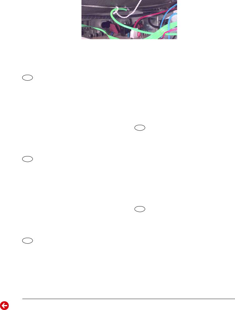
Masseleitung von Bildrohrplatte zum Masseband der Bildröhre:
Die Masseleitung ist am Masseband angeklemmt und verlötet. Muss die Leitung gelöst werden, sollte diese unmittelbar an der Klemmstelle abgetrennt werden. Beim Zusammenbau muss die Leitung nach dem
Anlöten mechanisch gesichert werden.
Defekte Bildröhre:
Im Defektfall der Bildröhre senden Sie Ihr Gerät an Ihre regionale Kundendienststelle.
Ground Wire from CRT Panel to the Ground Strap of the CRT:
The ground wire is clamped and soldered at the ground strap. To remove the wire cut it directly beside the clamp. When reassembling the wire must be secured mechanically after soldering.
Defective CRT:
In the event of a defective picture tube please send your TV set to your local After-Sales Service.
D
Service-Hinweise
Chassisausbau
Bevor Sie die Chassis-Verbindungsleitungen lösen, muss die LeitungsverlegungzudeneinzelnenBaugruppenwieNetzschalterplatte,Bedieneinheit, Bildrohrplatte, Ablenkeinheit oder Lautsprecher beachtet werden.
Nach erfolgter Reparatur ist es notwendig, die Leitungsführung wieder in den werkseitigen Zustand zu versetzen, um eventuell spätere
Ausfälle oder Störungen zu vermeiden.
Netzkabel
Diese Geräte dürfen nur mit dem Original-Netzanschlusskabel mit integrierter Entstördrossel betrieben werden. Dieses Netzkabel verhindert Störungen aus dem Netz und ist Bestandteil der Gerätezulassung. Im Ersatzfall bestellen Sie bitte ausschließlich das Netzkabel laut Ersatzteilliste.
GB
Service Notes
Disassembly of the chassis
Before disconnecting the chassis connecting leads observe the way they are routed to the individual assemblies like the mains switch panel, keyboard control panel, picture tube panel, deflection unit or loudspeaker.
On completion of the repairs the leads must be laid out as originally fitted at the factory to avoid later failures or disturbances.
Mains cable
The TV receiver must only be operated with an original mains connecting cable with an interference suppressor choke integrated in the mains plug.This mains cable prevents interference from the mains supply and is part of the product approval. For replacement please order exclusively the mains connecting cable specified in the spare parts list.
F
Information pour la maintenance
Dèmontage de chassis
Avant de défaire les connecteurs du châssis princip, il y a lieu de repérer auparavant les liaisons correspondant à chaque platine comme par exemple le C.I. Inter secteur, le C.I. Commande, le C.I. Tube, le bloc déviation ou les haut-parleurs.
A la fin de l'intervention, les connexions doivent être remises dans leur position d'origine afin d'éviter par après d'éventuelles défaillances ou perturbations.
Cable dereseau
Ces appareils ne peuvent être utilisés qu ' avec un cable de connecion original de réseau avec bobine antiparasite intégré dans la fiche de secteur. Ce câble de réseau empêche des perturbations de réseau et est partie de l'autorisation d'appareil. Si nécessaire commandez uniquement le cable de réseau selon la liste de pièces détachées.
I
Nota di servizio
Smontaggio del telaio
Prima di sfilare i cavi di collegamneto col telaio è necessario osservare la disposizione originaria degli stessi verso le singole parti come la piastra alimentazione, l'unità comandi, la piastra cinescopio, il giogo o l'altoparlante.
Dopo la riparazione è necessario che gli ancoraggi e le guide garantiscano la disposizione dei cavi analogamente a quella data in fabrica e ciò per evitare disturbi o danni nel tempo.
Cavo rete
Gli apperechi devono essere messi in funzioni solo con il cavo originale il colle gamento di rete e la sua spina di rete deve essere munita di una bombina d´induttanza. In causa di sostituzione ordinate solo il cavo di alimentatore che corrésponde alla lista degli accessori.
E
Nota de servicio
Desmontaje del chassis
Antes de desconectar las conecciones del Chassis hay que observar la dirección de dichas conecciones a los distintos grupos de construcción como la placa de conmutación de red, unidad de control, placa del zócalo del tubo de imagen, unidad de deflección o altavoces.
Después de haber realizado la reparación y para evitar fallos o pertubaciones posteriores es necesario reponer las conecciones tal como fueron instaladas originalmente en fabrica.
Cable de red
El aparato solo se puede usar con el cable de red original con choque antiparásito integrado en el enchufe de red. Este cable de red evita perturbaciones de la red y es parte de la autorización del aparato. En caso necesario puede pedir el cable de red según lista de piezas de repuestos.
GRUNDIG Service |
1 - 3 |

4 -1 |
|
|
DAVIO 37 |
|
DAVIO 37 |
|
DAVIO 37 |
|
DAVIO 51 |
|
|
|
|
P 37-2201 |
|
P 37-4201 TOP |
|
P 37-4201/5 TOP |
|
T 51-4201 TOP |
|
|
|
|
Chassis 12.5 |
|
Chassis 12.5 |
|
Chassis 12.5 |
|
Chassis 12.5 |
|
|
|
|
|
|
|
|
|
|
|
|
|
|
Bildröhre / Picture Tube |
|
|
|
|
|
|
|
|
|
|
|
|
|
|
|
|
|
|
|
|
|
Sichtbares Bild |
34cm |
|
34cm |
|
34cm |
|
48cm |
|
|
|
Visible picture |
|
|
|
|
||||
|
|
|
|
|
|
|
|
|
|
|
|
|
|
|
|
|
|
|
|
|
|
|
|
Bildröhre |
37cm (14") Black Matrix, |
|
37cm (14") Black Matrix, |
|
37cm (14") Black Matrix, |
|
51cm (20") Black Matrix, |
|
|
|
Picture tube |
Philips/90° |
|
Philips/90° |
|
Philips/90° |
|
Thomson/90°, (Samsung) |
|
|
|
|
|
|
|
|
|
|
|
|
|
|
Elektronik / Electronic |
|
|
|
|
|
|
|
|
|
|
|
|
|
|
|
|
|
|
|
|
|
Programmspeicherplätze |
99 + 2 AV |
|
99 + 2 AV |
|
99 + 2 AV |
|
99 + 2 AV |
|
|
|
Programme positions |
|
|
|
|
||||
|
|
|
|
|
|
|
|
|
|
|
|
|
|
|
|
|
|
|
|
|
|
|
|
Tuner |
|
|
PLL Frequenz Synthesizer Tuning UHF/VHF, globale Pinbelegung |
|
|
|
||
|
|
|
|
PLL frequency synthesizer tuning UHF/VHF, global pinning |
|
|
|
|||
|
|
|
|
|
|
|
|
|||
|
|
|
|
|
|
|
B/G, D/K/K' |
|
|
|
|
|
TV-Normen |
B/G |
|
B/G |
|
|
B/G |
|
|
|
|
|
|
PAL, SECAM, |
|
|
||||
|
|
TV-Standards |
PAL, via AV: NTSC 4.43MHz |
|
PAL, via AV: NTSC 4.43MHz |
|
|
PAL, via AV: NTSC 4.43MHz |
|
|
|
|
|
|
via AV: NTSC 4.43MHz |
|
|
||||
|
|
|
|
|
|
|
|
|
|
|
|
|
|
|
|
|
|
|
|
|
|
|
|
Videotext |
- |
|
7-Seiten-TOP/FLOF-Text |
|
7-Seiten-TOP/FLOF-Text |
|
7-Seiten-TOP/FLOF-Text |
|
|
|
Teletext |
|
7-pages TOP/FLOF text |
|
7-pages TOP/FLOF text |
|
7-pages TOP/FLOF text |
|
|
|
|
|
|
|
|
|
||||
|
|
|
|
|
|
|
|
|
|
|
|
|
Musikleistung |
Mono 5W |
|
Mono 5W |
|
Mono 5W |
|
Mono 5W |
|
|
|
Music power |
|
|
|
|
||||
|
|
|
|
|
|
|
|
|
|
|
|
|
|
|
|
|
|
|
|
|
|
|
|
Anschlüsse Front / Connections Front |
|
|
|
|
|
|
|
|
|
|
|
|
|
|
|
|
|
|
|
|
|
Kopfhörer |
|
|
Mono 3,5mm Klinkenbuchse, schaltet internen Lautsprecher ab |
|
|
|
||
|
|
Headphones |
|
|
Mono 3.5mm jack, aswitch off inserted speaker |
|
|
|
||
|
|
|
1 x FBAS Video/in |
|
1 x FBAS Video/in |
|
1 x FBAS Video/in |
|
1 x FBAS Video/in |
|
|
|
|
|
|
|
|
||||
|
|
Cinch-AV |
1 x CCVS Video/in |
|
1 x CCVS Video/in |
|
1 x CCVS Video/in |
|
1 x CCVS Video/in |
|
|
|
1 x Audio/in |
|
1 x Audio/in |
|
1 x Audio/in |
|
1 x Audio/in |
|
|
|
|
|
|
|
|
|
||||
|
|
|
(AV 2 Position) |
|
(AV 2 Position) |
|
(AV 2 Position) |
|
(AV 2 Position) |
|
|
|
|
|
|
|
|
|
|
|
|
|
|
Anschlüsse Rückwand / Connections Rear Panel |
|
|
|
|
|
|
|
|
|
|
|
|
|
|
|
|
|
|
|
|
|
|
FBAS Ein-/Ausgang, |
|
FBAS Ein-/Ausgang, |
|
FBAS Ein-/Ausgang, |
|
FBAS Ein-/Ausgang, |
|
|
|
Euro AV 1 (schwarz/black) |
RGB Eingang, Audio Eingang |
|
RGB Eingang, Audio Eingang |
|
RGB Eingang, Audio Eingang |
|
RGB Eingang, Audio Eingang |
|
|
|
CCVS in-/output, |
|
CCVS in-/output, |
|
CCVS in-/output, |
|
CCVS in-/output, |
|
|
|
|
|
|
|
|
|
||||
|
|
|
RGB input, audio input |
|
RGB input, audio input |
|
RGB input, audio input |
|
RGB input, audio input |
|
|
|
|
|
|
|
|
|
|
|
|
|
|
Antenne |
Koaxial-Buchse DIN 45325 |
|
Koaxial-Buchse DIN 45325 |
|
Koaxial-Buchse DIN 45325 |
|
Koaxial-Buchse DIN 45325 |
|
|
|
Antenna |
Coaxial socket acc. DIN 45325 |
|
Coaxial socket acc. DIN 45325 |
|
Coaxial socket acc. DIN 45325 |
|
Coaxial socket acc. DIN 45325 |
|
|
|
|
|
|
|
|
|
|
|
|
|
|
Netzteil / Mains Stage |
|
|
|
|
|
|
|
|
|
|
|
|
|
|
|
|
|
|
|
|
|
Netzspannung (Regelbereich) |
230V ±15% |
|
230V ±15% |
|
230V ±15% |
|
230V ±15% |
|
|
|
Mains voltage (variable) |
|
|
|
|
||||
|
|
|
|
|
|
|
|
|
|
|
|
|
|
|
|
|
|
|
|
|
|
|
|
Netzfrequenz |
50 / 60Hz |
|
50 / 60Hz |
|
50 / 60Hz |
|
50 / 60Hz |
|
|
|
Mains frequency |
|
|
|
|
||||
|
|
|
|
|
|
|
|
|
|
|
|
|
|
|
|
|
|
|
|
|
|
|
|
Leistungsaufnahme |
ca. 40W |
|
ca. 40W |
|
ca. 40W |
|
ca. 50W |
|
|
|
Power consumption |
|
|
|
|
||||
|
|
|
|
|
|
|
|
|
|
|
ServiceGRUNDIG |
|
|
|
|
|
|
|
|
|
|
|
Standby |
ca. 4W |
|
ca. 4W |
|
ca. 4W |
|
ca. 4W |
|
|
|
|
|
|
|
|
|||||
|
|
|
|
|
|
|
|
|
|
|
|
|
|
|
|
|
|
|
|
|
|
Technical / Daten Technische |
Section General / Teil Allgemeiner |
Data |
|
5.12 Chassis

GRUNDIG |
|
|
Chassis 12.5 |
|
Chassis 12.5 |
|
Chassis 12.5 |
|
|
|
|
DAVIO 51 |
|
DAVIO 55 |
|
DAVIO 55 |
|
|
|
|
T 51-4201/5 TOP |
|
T 55-4201 TOP |
|
T 55-4201/5 TOP |
|
Service |
|
|
|
|
|
|
|
|
|
Bildröhre / Picture Tube |
|
|
|
|
|
|
|
|
|
|
|
|
|
|
|
|
|
|
|
|
|
|
|
|
|
|
|
Sichtbares Bild |
48cm |
|
51cm |
|
51cm |
|
|
|
Visible picture |
|
|
|
|||
|
|
|
|
|
|
|
|
|
|
|
|
|
|
|
|
|
|
|
|
Bildröhre |
51cm (20") Black Matrix, |
|
55cm (21"), FST, Black Matrix, |
|
55cm (21"), FST, Black Matrix, |
|
|
|
Picture tube |
Thomson/90°, (Samsung) |
|
Philips/90°, (Thomson/Samsung) |
|
Philips/90°, (Thomson/Samsung) |
|
|
|
|
|
|
|
|
|
|
|
|
Elektronik / Electronic |
|
|
|
|
|
|
|
|
|
|
|
|
|
|
|
|
|
Programmspeicherplätze |
99 + 2 AV |
|
99 + 2 AV |
|
99 + 2 AV |
|
|
|
Programme positions |
|
|
|
|||
|
|
|
|
|
|
|
|
|
|
|
|
|
|
|
|
||
|
|
Tuner |
PLL Frequenz Synthesizer Tuning UHF/VHF, globale Pinbelegung |
|
||||
|
|
PLL frequency synthesizer tuning UHF/VHF, global pinning |
|
|||||
|
|
|
|
|||||
|
|
|
B/G, D/K/K' |
|
|
|
B/G, D/K/K' |
|
|
|
TV-Normen |
|
B/G |
|
|
||
|
|
PAL, SECAM, |
|
|
PAL, SECAM, |
|
||
|
|
TV-Standards |
|
PAL, via AV: NTSC 4.43MHz |
|
|
||
|
|
via AV: NTSC 4.43MHz |
|
|
via AV: NTSC 4.43MHz |
|
||
|
|
|
|
|
|
|
||
|
|
|
|
|
|
|
|
|
|
|
Videotext |
7-Seiten-TOP/FLOF-Text |
|
7-Seiten-TOP/FLOF-Text |
|
7-Seiten-TOP/FLOF-Text |
|
|
|
Teletext |
7-pages TOP/FLOF text |
|
7-pages TOP/FLOF text |
|
7-pages TOP/FLOF text |
|
|
|
|
|
|
|
|
|
|
|
|
Musikleistung |
Mono 5W |
|
Mono 5W |
|
Mono 5W |
|
|
|
Music power |
|
|
|
|||
|
|
|
|
|
|
|
|
|
|
|
|
|
|
|
|
|
|
|
|
Anschlüsse Front / Connections Front |
|
|
|
|
|
|
|
|
|
|
|
|
|
||
|
|
Kopfhörer |
Mono 3,5mm Klinkenbuchse, schaltet internen Lautsprecher ab |
|
||||
|
|
Headphones |
|
Mono 3.5mm jack, aswitch off inserted speaker |
|
|
||
|
|
|
1 x FBAS Video/in |
|
1 x FBAS Video/in |
|
1 x FBAS Video/in |
|
|
|
|
|
|
|
|||
|
|
Cinch-AV |
1 x CCVS Video/in |
|
1 x CCVS Video/in |
|
1 x CCVS Video/in |
|
|
|
1 x Audio/in |
|
1 x Audio/in |
|
1 x Audio/in |
|
|
|
|
|
|
|
|
|||
|
|
|
(AV 2 Position) |
|
(AV 2 Position) |
|
(AV 2 Position) |
|
|
|
|
|
|
|
|
|
|
|
|
Anschlüsse Rückwand / Connections Rear Panel |
|
|
|
|
|
|
|
|
|
|
|
|
|
|
|
|
|
|
FBAS Ein-/Ausgang, |
|
FBAS Ein-/Ausgang, |
|
FBAS Ein-/Ausgang, |
|
|
|
Euro AV 1 (schwarz/black) |
RGB Eingang, Audio Eingang |
|
RGB Eingang, Audio Eingang |
|
RGB Eingang, Audio Eingang |
|
|
|
CCVS in-/output, |
|
CCVS in-/output, |
|
CCVS in-/output, |
|
|
|
|
|
|
|
|
|||
|
|
|
RGB input, audio input |
|
RGB input, audio input |
|
RGB input, audio input |
|
|
|
|
|
|
|
|
|
|
|
|
Antenne |
Koaxial-Buchse DIN 45325 |
|
Koaxial-Buchse DIN 45325 |
|
Koaxial-Buchse DIN 45325 |
|
|
|
Antenna |
Coaxial socket acc. DIN 45325 |
|
Coaxial socket acc. DIN 45325 |
|
Coaxial socket acc. DIN 45325 |
|
|
|
|
|
|
|
|
|
|
|
|
Netzteil / Mains Stage |
|
|
|
|
|
|
|
|
|
|
|
|
|
|
|
|
|
Netzspannung (Regelbereich) |
230V ±15% |
|
230V ±15% |
|
230V ±15% |
|
|
|
Mains voltage (variable) |
|
|
|
|||
|
|
|
|
|
|
|
|
|
|
|
|
|
|
|
|
|
|
|
|
Netzfrequenz |
50 / 60Hz |
|
50 / 60Hz |
|
50 / 60Hz |
|
|
|
Mains frequency |
|
|
|
|||
|
|
|
|
|
|
|
|
|
|
|
|
|
|
|
|
|
|
|
|
Leistungsaufnahme |
ca. 50W |
|
ca. 50W |
|
ca. 50W |
|
|
|
Power consumption |
|
|
|
|||
|
|
|
|
|
|
|
|
|
|
|
|
|
|
|
|
|
|
|
|
Standby |
ca. 4W |
|
ca. 4W |
|
ca. 4W |
|
5 - 1 |
|
|
|
|
|
|
|
|
|
|
|
|
|
|
|
|
|
|
|
|
|
|
|
|
|
|
|
|
|
|
|
|
|
|
|
.werden verwendet Typen vorgeschriebenen sten |
-Ersatzteilli den in die nur dürfen Bildröhre der Austausch Beim |
.vermeiden zu Bildröhre |
der an oder Chassis am Folgeschäden um werden, gesetzt |
Betrieb außer kurzzeitig nur dürfen Gerät im Schutzschaltungen |
.zustellen |
-ein gegebenenfalls und messen zu Hochspannung die ist kung |
-Horizontalablen der in oder Netzteil im Reparatur jeder Nach |
.+B Netzteilspannung |
der Einstellung exakten der von abhängig ist Röntgenstrahlung |
auftretende damit die und Bildröhre die für Hochspannung Die |
.1987 Januar .8 vom desanstalt |
-Bun Technischen-Physikalisch der Bestimmungen den spricht |
-ent Röntgenstrahlung auftretende Fernsehgeräten den in Die |
Hinweise-Sicherheits |
|
|
|
|
|
|
|
|
|
|
|
|
|
|
|
|
|
|
|
.lists parts spare the |
in specified types the only use tube picture the replacing When |
.time short a for only operation of |
out put be to allowed are circuits protective integrated the tube |
picture the or chassis the to damages consequential avoid To |
.necessary if adjusted-re and checked |
is tube picture the for EHT the that imperative is it stage flection |
-de horizontal the or unit supply power the of repair every After |
.supply |
power +B the of adjustment precise the on depends radiation |
-X developing the thus and tube picture the for tension high The |
.institution) physiotechnical (federal Bundesanstalt Technische |
-Physikalisch the by issued 1987), 8, (January Regulations on |
-radiati-X the to conforms sets the in developing radiation-X The |
Advices Safety |
|
|
|
|
|
|
|
|
|
|
|
|
|
|
|
|
|
|
5.12 Chassis
Section General / Teil Allgemeiner

6 - 1
Service GRUNDIG
Bedienhinweise Dieses Kapitel enthält Auszüge aus der Bedienungsanleitung.
Weitergehende Informationen entnehmen Sie bitte der gerätespezifischen Bedienungsanleitung, deren Materialnummer Sie in der entsprechenden Ersatzteilliste finden.
Section General / Teil Allgemeiner
5.12 Chassis
Chassis 12.5 |
Allgemeiner Teil / General Section |
GRUNDIG Service |
1 - 7 |
8 - 1
Service GRUNDIG
Operating Hints This chapter contains excerpts from the operating instructions.
For further particulars please refer to the appropriate user instructions the part number of which is indicated in the relevant spare parts list.
Section General / Teil Allgemeiner
5.12 Chassis
Chassis 12.5 |
Allgemeiner Teil / General Section |
GRUNDIG Service |
1 - 9 |
Loading...