


LXW 82-8625 IDTV

COLOR
TELEVISION
Xentia 32
LXW 82-8625 IDTV
Xentia 37
LXW 94-8625 IDTV

Installation 3
Remote control handset 4-5
Controls 4
Battery installation 5
Controls of
Front panel 6
Connections of
Back panel 7
Connection to
External equipment 8-12
Basic operation
On and Off 13
Programme selection 13
Volume adjustment 13
On screen language selection 13
On screen menus
Menu selection 14
Setting up TV stations 15-23
Sound adjustment 15-18
Picture adjustment 19-21
Child lock 22
Timer 23-25
DTV option Menu (in digital mode only) 26-29
Preset list Menu 30-32
Installation Menu 33
Other Menu 34
Connection of PC 35
PIP (Picture-In-Picture) Feature 36-37
Watching PIP 36
PIP Audio input 36
Moving the PIP 37
Sub picture size 37
Programme scan 37
Information Menu (In Digital mode only) 38
Teletext 39-40
Displayable Monitor Specification 41
Troubleshooting
Check list 43
Contents
2
Power
This set operates on an AC mains supply, the voltage is as
indicated on the label on the back cover. Never apply DC
power to the set. In the event of thunderstorms or power-
cuts, please pull out the aerial and mains plugs.
Warning
To prevent fire or shock hazard, do not expose the set to
rain or moisture. Do not rub or strike the Active Matrix LCD
with anything hard as this may scratch, mar, or damage the
Active Matrix LCD permanently.
Service
Never remove the back cover of the set as this can expose
you to very high voltage and other hazards. If the set does
not operate properly, unplug it and call your dealer.
Aerial
Connect the aerial cable to the socket marked +75 on
the back cover. For the best reception an outdoor aerial
should be used.
Location
Position your set so that no bright light or sunlight falls
directly onto the screen. Care should be taken not to
expose the set to any unnecessary vibration, moisture,
dust or heat. Also ensure that the set is placed in a posi-
tion to allow a free flow of air. Do not cover the ventilation
openings on the back cover.
Cleaning
Unplug the set before cleaning the face of the LCD Screen.
Dust the set by wiping the screen and the cabinet with a
soft, clean cloth. If the screen requires additional cleaning,
use a clean, damp cloth. Do not use liquid cleaners or
aerosol cleaners.
Installation
3
EN
To preserve the Environment,
do not rubbish.
- All the functions can be controlled with the remote control handset.
- Some functions can also be adjusted with the buttons on the front panel of the set.
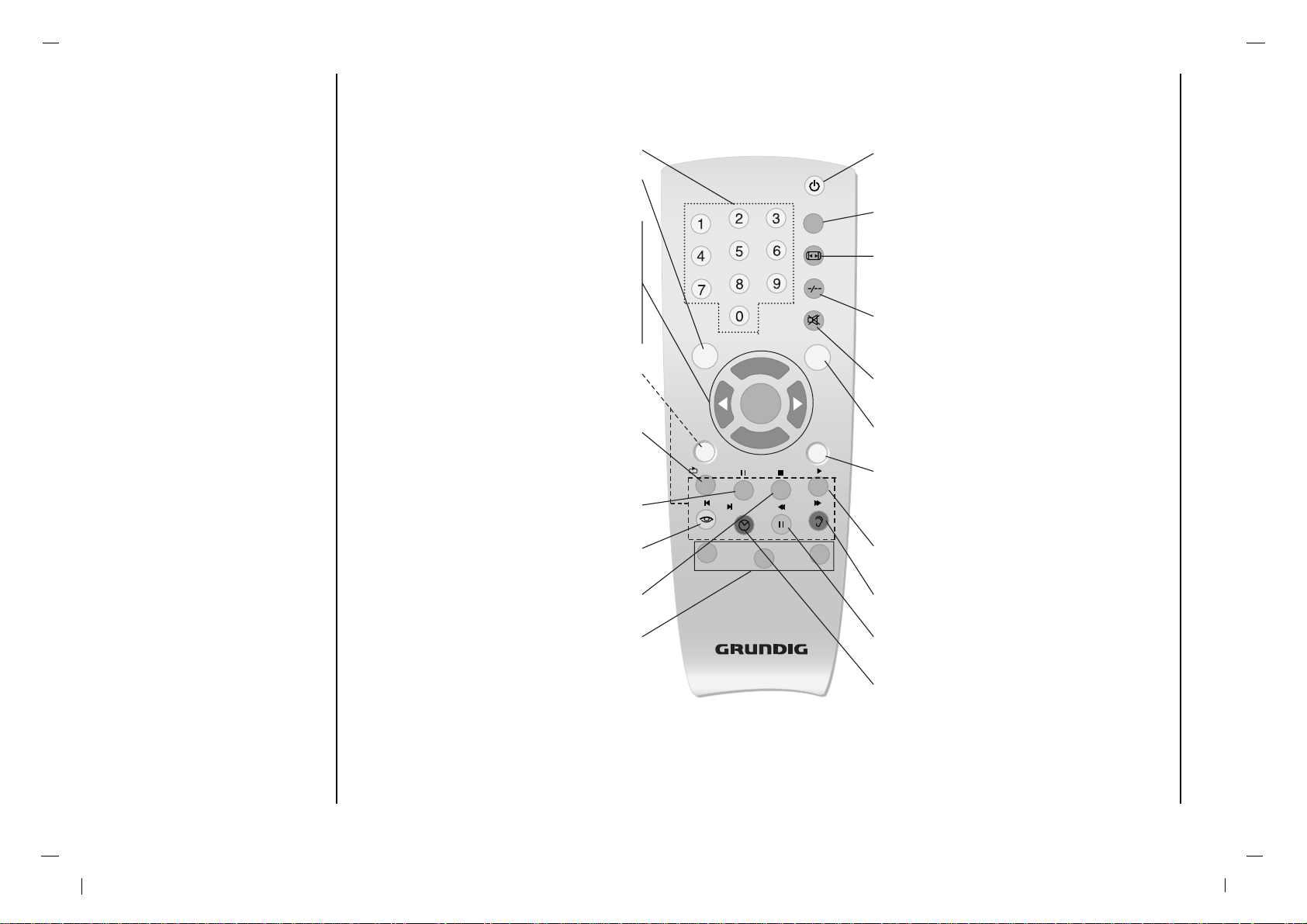
Remote control handset
Controls
Before you use the remote
control handset, please
install the batteries.
4
NUMBER BUTTONS
i BUTTON
selects a menu.
D
/
E
(Programme Up/Down)
selects a programme or a menu item.
switches the set on from standby.
F / G (Volume Up/Down)
adjusts the volume.
adjusts menu settings.
OK
accepts your selection or displays the
current mode.
TELETEXT BUTTONS
These buttons are used for teletext.
For further details, see the ‘Teletext’ section.
SCAN
switches on the programme scan mode
through 4/16 sub pictures.
Display the TV Guide in digital mode.
P AP (Picture And Picture)
selects the double window function.
PSM (Picture Status Memory)
recalls your preferred picture setting.
SIZE
adjusts the sub picture size.
VCR, SAT, DVD
Switches to operating a GRUNDIG video
recorder, a GRUNDIG satellite receiver
or a GRUNDIG DVD player.
Keep the appropriate button VCR, SAT, DVD
pressed down. Then press the appropri-
ate button
Note : The functions available depend on the
model of the device you are using.
Just try it out.
POWER
switches the set On from standby or Off to
standby.
PIP
Switches the sub picture On or Off.
ARC
select your desired picture format.
page stop in teletext mode.
SLEEP
sets the sleep timer.
select a sub page number in teletext mode.
MUTE
switches the sound On or Off.
Zap function
returns to the previously viewed programme.
AV INPUT
Select DTV, TV, AV1, AV2, S-VIDEO, COMPO-
NENT, PC-RGB, HDMI mode.
switches the set on from standby.
PIP POSITION
relocates the sub picture in clockwise direction.
SSM (Sound Status Memory)
recalls your preferred sound setting.
STILL
freezes motion of the sub picture.
TIME
Display the time at the screen.
Selects a favourite programme add and delete
in digital mode.
- COLOURED BUTTONS
These buttons are used for teletext (only
TELETEXT models) or programme edit.
PIP
P+
OK
P-
SCAN
SIZE
PAP
POS
VCR
SAT
DVD
i
Z
/ TV-G
-
+
TXT
AV
/ Add Del
Tele Pilot 160A
EN
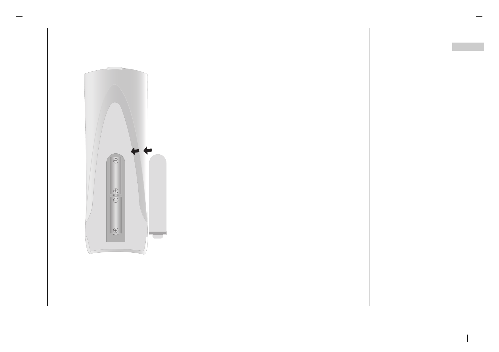
Remote control handset
Battery installation
5
- Your remote control handset is powered by two AA type batteries.
- To insert batteries, turn the remote control handset over and
remove the battery cover.
- Put the two batteries into the compartment observing battery
polarity.
- Replace the cover.
To avoid damage from possible battery leakage, remove the bat-
teries if you do not plan to use the remote control handset for an
extended period time. Do not use batteries of differing age or type.
Always discard of batteries safely.
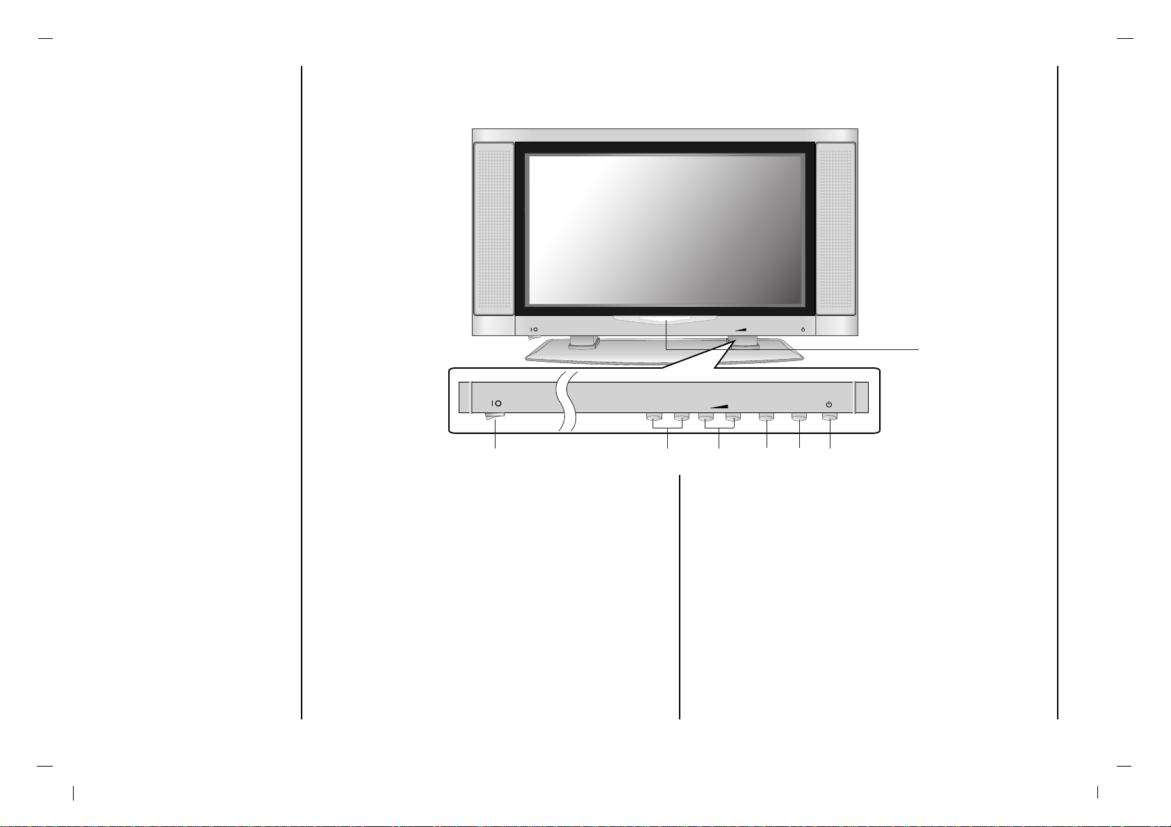
Controls of
Front panel
6
1. MAIN POWER (I yy )
switches the set On or Off.
2.
D
/
E
(Programme Up/Down)
selects a programme or a menu item.
switches the set On from standby.
3. F / G (Volume Down/Up)
adjusts the volume.
adjusts menu settings.
4. MENU
selects a menu.
5. TV/AV
selects DTV, TV, AV 1 , AV 2 , S-VIDEO, COMPO-
NENT
, PC-RGB, HDMI mode.
6. POWER (rr)
switches the set On from standby or On to standby.
7. POWER/STANDBY INDICATOR (rr)
illuminates red in standby mode.
illuminates green when the set is switched On.
8. REMOTE CONTROL SENSOR
TV/ATV/AV
MENU MENUP
+
-
+
-
TV/ATV/AV
MENU MENU
P
+
-
+
-
1
4
5
6
7, 8
32
- Shown is a simplified representation of the set.
- Here shown may be somewhat different from your set.
- This manual explains the features available on the Xentia series.

Connections of
Back panel
7
EN
1. HDMI INPUT / RGB INPUT / AUDIO INPUT SOCKETS
Connect the set output socket of the PERSONAL
COMPUTER to this socket.
2. AUDIO INPUT / COMPONENT INPUT (480i / 576i /
480p / 576p / 720p / 1080i) SOCKETS
3. AUDIO/VIDEO SOCKET
Connect the audio/video out sockets of the VCR to AV
sockets of the set.
4. S-VIDEO INPUT
connect video out from an S-VIDEO VCR to the S-
VIDEO input.
5. SERVICE SOCKET
6. AERIAL SOCKET
7. Digital Audio (OPTICAL)
Connect digital audio from various types of equipment.
Note : In standby mode, these ports will not work.
8. POWER CORD SOCKET
This set operates on an AC power. The voltage is indi-
cated on the Specifications page. Never attempt to
operate the set on DC power.
RGB INPUTRGB INPUT
AUDIO INPUTAUDIO INPUT
SERSERVICEVICE OPTICALOPTICAL
AUDIO INPUTAUDIO INPUT
AUDIOAUDIO
R L
COMPONENT INPUT
(480i/480p/720p/1080i)
Y P
b
P
r
S-VIDEOS-VIDEO
ANTANT. IN. IN
AC INPUTAC INPUT
HDMI INPUTHDMI INPUT
AV1V1
VIDEOVIDEO
AUDIOAUDIO
L
R
AV2V2
VIDEOVIDEO
AUDIOAUDIO
L
R
1 2 3 4 5 6 7 8
Connection to
External equipment
8
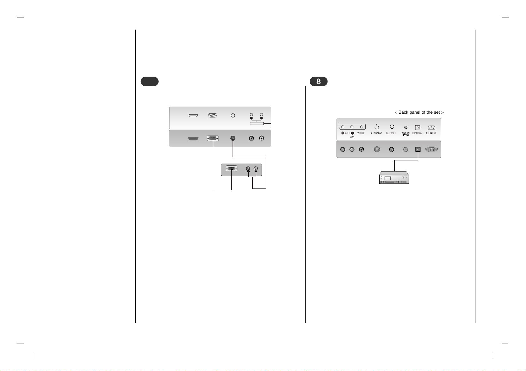
- You can connect additional equipment, such as VCRs, camcorders etc. to your set. However please check with your
manufacturers instruction books for specific information. Make sure all connections are made with both your set and
additional appliance unplugged from the mains to avoid damaging your equipment. Here shown may be somewhat dif-
ferent from your set.
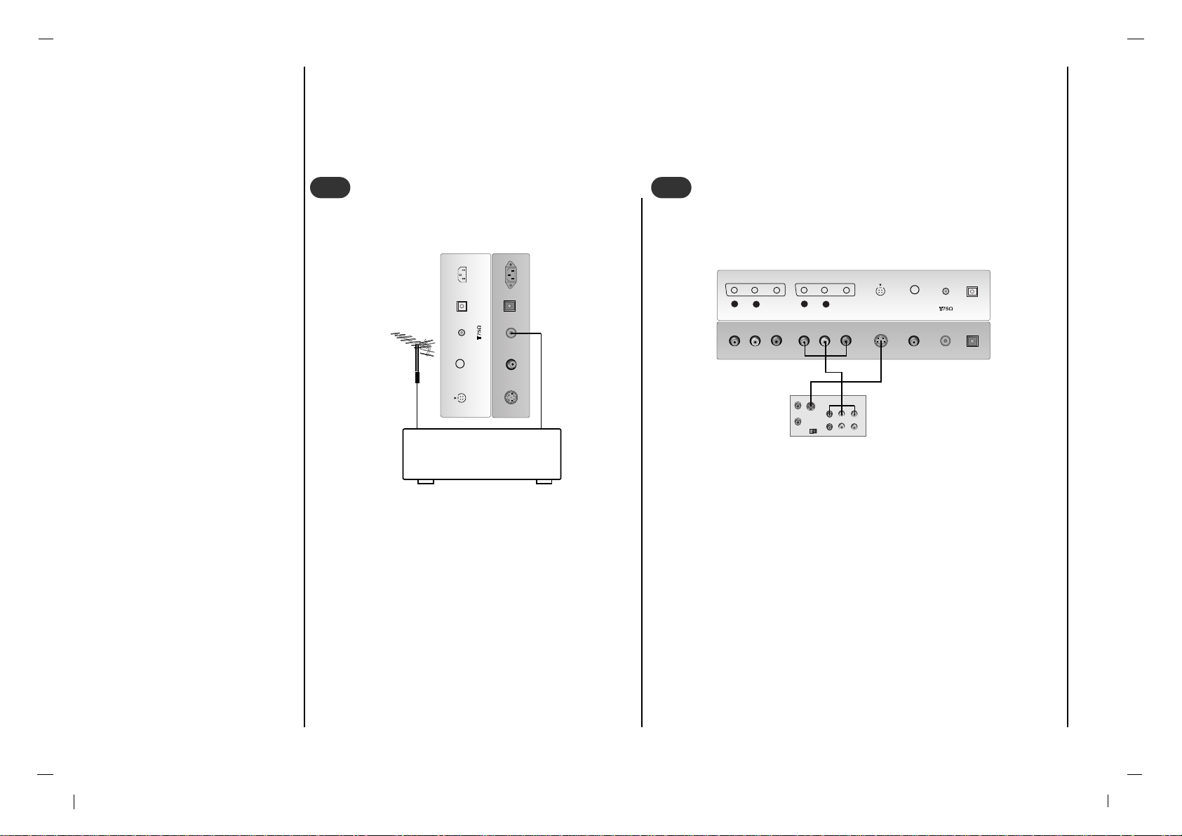
Connect the RF out socket of the VCR to the aerial
socket on the back of the set.
Connect the aerial cable to the RF aerial in socket
of the VCR.
Store the VCR channel on a desired programme
number using the ‘Manual programme tuning’ sec-
tion.
Select the programme number where the VCR
channel is stored.
Press the PLAY button on the VCR.
Connect to Aerial socket
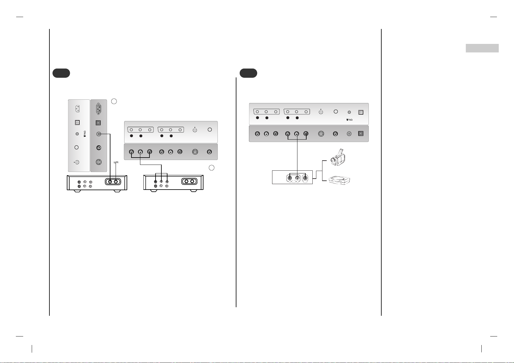
- If you connect an S-VIDEO VCR to the S-VIDEO input, the pic-
ture quality is improved; compared to connecting a regular VCR
to the Video input.
- To avoid picture noise (interference), leave an adequate dis-
tance between the VCR and set.
Use the INPUT SELECT button on the remote control to select
AV 1 or AV 2 .
(If connected to S-VIDEO, select the S-Video external input
source.)
Insert a video tape into the VCR and press the PLAY button on the
VCR. (See VCR owner’s manual)
Watching VCR
SERVICE OPTICAL
S-VIDEOS-VIDEO
ANTANT. IN. IN
AC INPUTAC INPUT
VCR
SERVICE OPTICAL
S-VIDEOS-VIDEO
ANTANT. IN. IN
AV1V1
VIDEOVIDEO
AUDIOAUDIO
L
R
AV2V2
VIDEOVIDEO
AUDIOAUDIO
L
R
S-VIDEO
OUT
IN
(R) AUDIO (L) VIDEO
1
1
2
2
< Back panel of the set >
< Back panel of the set >
< Back panel of VCR >
Connection to
External equipment
9
EN
- After subscribing for a local cable TV station and installing a con-
verter you can watch cable TV.
- For further information of cable TV, contact the local cable TV
station.
In using connection 1
Select programme number in programme switch of cable box.
Match the set programme with selected programme of cable box.
Select your desired programme with the remote control for cable
box.
In using connection 2
Use the INPUT SELECT button on the remote control and select
AV 1 or AV 2 .
Tune to cable service provided channels using the cable box.
SERVICE OPTICAL
S-VIDEOS-VIDEO
ANTANT. IN. IN
AC INPUTAC INPUT
SERVICE
S-VIDEOS-VIDEO
AV1V1
VIDEOVIDEO
AUDIOAUDIO
L
R
AV2V2
VIDEOVIDEO
AUDIOAUDIO
L
R
Cable
TV
(R) AUDIO (L) VIDEO
VCR
RF
Cable
TV
(R) AUDIO (L) VIDEO
VCR
RF
Watching Cable TV
3
3
When connecting the set to an external source,
match the colours of AUDIO/VIDEO input jacks on
the set with the output jacks on the audio/video
equipment: Video = yellow, Audio (Left) = white,
Audio (Right) = red.
Use the INPUT SELECT button on the remote con-
trol to select AV 1 or AV 2 .
Operate the corresponding external equipment.
See external equipment operating guide.
SERVICE OPTICAL
S-VIDEOS-VIDEO
ANTANT. IN. IN
AV1V1
VIDEOVIDEO
AUDIOAUDIO
L
R
AV2V2
VIDEOVIDEO
AUDIOAUDIO
L
R
RL
AUDIO VIDEO
Watching external AV source
4
4
For cable TV
< Cable Box >
< Back panel of the set >
< Back panel of the set >
Camcorder
Video game set
< Back panel of the external
equipment >
2
1
Connection to
External equipment
10
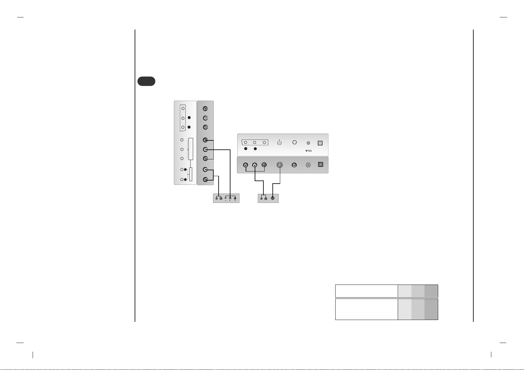
• Component Input ports
You can get better picture quality if you connect DVD player with
component input ports as below.
How to connect
Connect DVD video inputs to Y, PB, PR of COMPONENT (DVD INPUT) and audio inputs to Audio sockets of AUDIO
INPUT.
How to use
Turn on the DVD player, and insert a DVD.
Use INPUT SELECT button on the remote control to select Component. Refer to the DVD player's manual for oper-
ating instructions.
Watching DVD
SERVICE OPTICAL
S-VIDEOS-VIDEO
ANTANT. IN. IN
AV2V2
VIDEOVIDEO
AUDIOAUDIO
L
R
AUDIO INPUTAUDIO INPUT
AUDIOAUDIO
R L
COMPONENT COMPONENT INPUT INPUT
(480i/480p/720p/1080i)(480i/480p/720p/1080i)
Y P
b
P
r
AV1V1
VIDEOVIDEO
AUDIOAUDIO
L
R
B
R
(R) AUDIO (L)
(R) AUDIO (L)
S-VIDEO
5
5
< Back panel of the set >
< Back panel of a DVD player >
or
Component ports of the
set
Y PB
PR
Video output ports
of DVD player
Y
Y
Y
Y
Pb
B-Y
Cb
PB
Pr
R-Y
Cr
P
R
Connection to
External equipment
11
EN
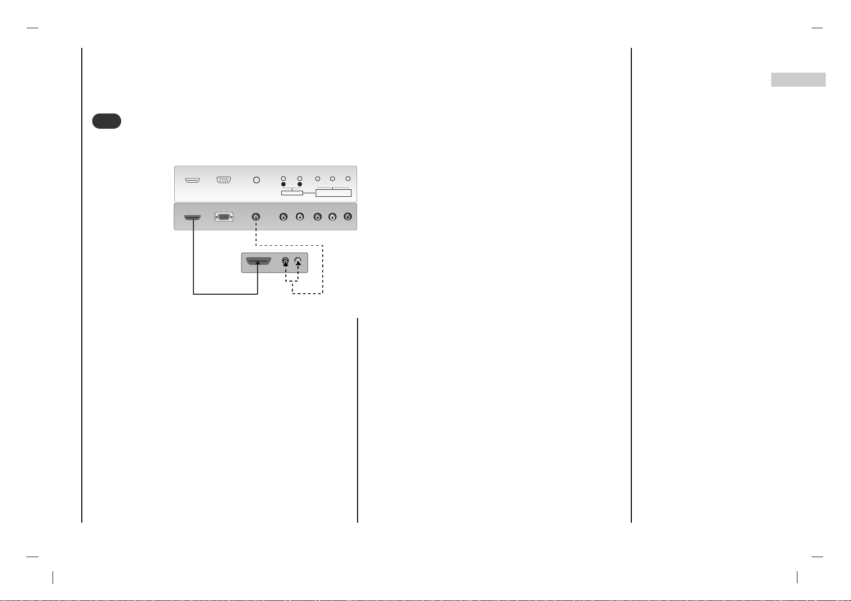
Connect the signal cable from the monitor output socket of
the DVD player or Set top Box to the HDMI INPUT socket
of the set.
Connect the audio cable from the PC to the AUDIO INPUT
sockets of the set.
Press the INPUT SELECT button to select HDMI.
Switch on the HDMI, and the HDMI screen appears on the
set.
HDMI input signal : 480p-60Hz, 576p-50Hz, 720p-50Hz,
720p-60Hz, 1080i-50Hz, 1080i-60Hz.
HDMI Interface with HDCP Copy Protection enables all-
digital rendering of video without the losses.
This TV SET can receive the High-Definition Multimedia
Interface(HDMI) or Input of Digital Visual Interface(DVI).
Connecting HDMI
RGB INPUTRGB INPUT
AUDIO INPUTAUDIO INPUT
AUDIO INPUTAUDIO INPUT
AUDIOAUDIO
R L
COMPONENT COMPONENT INPUT INPUT
(480i/480p/720p/1080i)(480i/480p/720p/1080i)
Y P
b
P
r
HDMI INPUTHDMI INPUT
HDMI OUTPUTHDMI OUTPUT
(R) (R) AUDIO (L)AUDIO (L)
6
6
< Back panel of the set >
< DVI signal input only>
Connection to
External equipment
12
Connect the signal cable from the monitor output socket
of the PERSONAL COMPUTER to the RGB INPUT sock-
et of the set.
Connect the audio cable from the PC to the AUDIO
INPUT sockets of the set.
Press the INPUT SELECT button to select PC-RGB.
Switch on the PC, and the PC screen appears on the set.
The set can be operated as the PC monitor.
RGB input signal : 480p-60Hz, 576p-50Hz, 720p-50Hz,
720p-60Hz, 1080i-50Hz, 1080i-60Hz.
Connecting PC
RGB INPUT
AUDIO INPUT
HDMI INPUT
AUDIO INPUTAUDIO INPUT
AUDIOAUDIO
R L
RGB OUTPUTRGB OUTPUT
(R) (R) AUDIO (L)AUDIO (L)
7
7
< Back panel of the set >
- Send the set’s audio to external audio equipment (stereo
system) via the Digital Audio Output (Optical)
Caution : Do not look into the optical output port. Looking
at the laser beam may damage your vision.
How to connect
Connect one end of an optical cable to the TV Digital
Audio (Optical) Output port.
Connect the other end of the optical cable to the digital
audio (optical) input on the audio equipment.
Note : Digital Audio Output works, when it’s inputted
HDMI signal to the set.
Connecting Digital Audio
SERVICE OPTICAL
S-VIDEO
ANT.IN. IN
AC INPUTAC INPUT
AV2
VIDEO
AUDIO
L
R
8
8
< Back panel of the set >

13
EN
Basic operation
Press the F / G button to adjust the
volume.
If you want to switch the sound off,
press the MUTE button.
You can cancel it by pressing the
MUTE, F / G, button.
You can select a programme number
with the
D
/
E
or NUMBER buttons.
Press the main power button to
switch the set on.
If the set is in standby mode, press
the POWER,
D
/
E
buttons on the
remote control handset to switch it
on fully.
Press the POWER button on the
remote control handset.
The set reverts to standby mode.
Press the main power button again
to switch the set off.
1
1
On and Off
2
2
Programme selection
3
3
Volume adjustment
Press the button and then use
D
/
E
button to select the Installation menu.
Press the OK button and then use
D
/
E
button to select Language.
Press the OK button and then use
D
/
E
button to select your desired language.
All the on screen displays will appear in
the selected language.
Press the button to return to normal
TV viewing.
4
4
On screen language selec-
tion
i
i
14
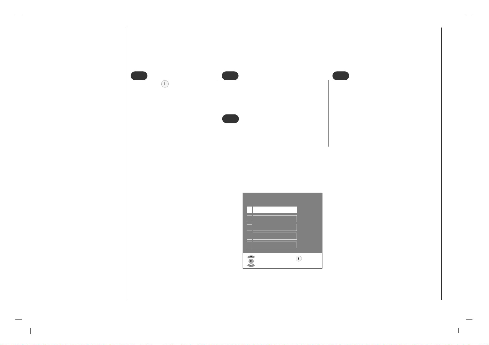
- The dialogue between you and your set takes place on screen with an operator menu. The buttons required for the
operating steps are also displayed.
Press the button and then
use
D
/
E
button to display each
menu.
1
1
Press the OK button and then use
D
/
E
button to select a menu item.
2
2
Press the OK button to display the sub
menu or the pull-down menu.
3
3
Change the setting of an item in the sub
or pull-down menu with F / G or
D
/
E
.
You can move to the higher level menu
with F button and to move to the lower
level menu press the G button.
Note : Menus may vary according to
input mode.
4
4
On screen menus
Menu selection
INFO
GRUNDIG
1
Settings
2
Preset list
3
Installation
4
PIP
5
Information
Select
and open
Exit
i
P+
OK
P-
i
 Loading...