


Vari-Green Motor
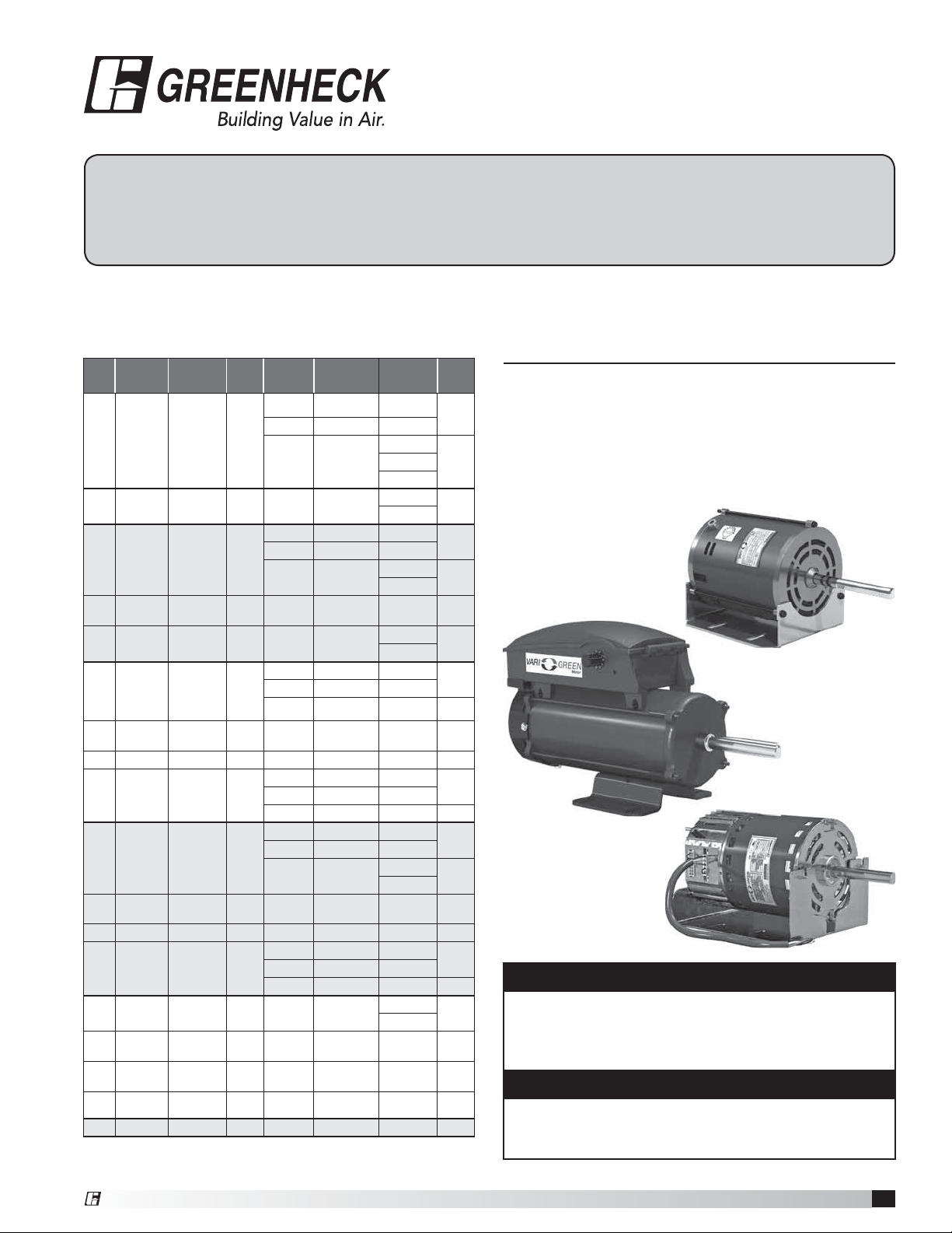
1
Vari-Green Motor and Controls
Installation, Operation and Maintenance Manual
Please read and save these instructions for future reference. Read carefully before attempting to assemble, install,
operate or maintain the product described. Protect yourself and others by observing all safety information. Failure
to comply with instructions could result in personal injury and/or property damage!
Table of Contents
Reference part number listed in chart to locate specific motor
information page number.
HP Voltage
*
RPM
Range
Encl. FLA
Control
Method
Motor
Part No.
Pg.
1/6 115 300-1725 TENV
3.1 0-10V Only 311352
2
3.1 Pot Only 311353
3.4 Pot/0-10V
311731
3312359
313712
1/6 208-240 300-1725 TENV 1.6 Pot/0-10V
313233
3
313713
1/4 115 300-1725 ODP
3.9 0-10V Only 310107
2
3.9 Pot Only 310108
3.7 Pot/0-10V
311377
3
313714
1/4
115/
208-240
300-1725 ODP 3.3/1.8 Pot/0-10V 310175 6
1/4 208-240 300-1725 ODP 2.3 Pot/0-10V
313234
3
313715
1/2 115 300-1725 ODP
6.2 0-10V Only 309025
2
6.2 Pot Only 309028
6.7 Pot/0-10V 311812 3
1/2
115/
208-240
300-1725 ODP 6.8/3.5 Pot/0-10V 310176 6
1/2 208-240 300-1725 ODP 4.2 Pot/0-10V 313235 3
1/2 115 300-2500 ODP
6.5 0-10V Only 310307
2
6.5 Pot Only 310476
6.5 Pot/0-10V 312360 3
3/4 115 300-1725 ODP
10.1 0-10V Only 309026
2
10.1 Pot Only 309029
10.6 Pot/0-10V
311388
3
312619
3/4
115/
208-240
300-1725 ODP 9.0/4.9 Pot/0-10V 310177 6
3/4 208-240 300-1725 ODP 6.6 Pot/0-10V 314534 3
3/4 115 300-2200 ODP
11.3 0-10V Only 310306
2
11.3 Pot Only 310475
11.3 Pot/0-10V 312361 3
1 115 300-1725 ODP 12.4 Pot/0-10V
310359
3
312362
1
115/
208-240
300-1725 ODP 11.4/6.3 Pot/0-10V 310178 6
1
115/
208-240
300-1725 TEFC 12.0/6.0 Pot/0-10V 311156 4
1 208-240 300-1725 ODP 8.6 Pot/0-10V 314945 3
2 208-240 300 - 1725 TEFC 12.0 Pot/0-10V 310420 4
*
Actual maximum RPM may vary. See RPM column in chart on
pg.10 for specific motor and fan combinations.
Vari-Green
®
Motor
The Vari-Green Motor is an electronically commutated
(EC) motor that uses AC input power and internally
converts it to a DC power supply which provides an
80% turndown capability and increased energy savings.
NOTE
When using a clamp meter to measure input amp
draw, the meter must be capable of reading a
non-linear current. Erroneous readings will occur
otherwise.
WARNING
To reduce the risk of fire or electric shock,
do not use this motor with any solid-state speed
control device.
Controls .................................7-9
Maximum RPM Table ....................... 10
®
®
Document 473681
Vari-Green
®
Motor and Controls
2
Vari-Green Motor and Controls
Operation and Wiring
-
Potentiometer Dial Only
These motors feature a potentiometer dial on the motor
for speed adjustment. A small screwdriver can be used
to make the speed adjustment. To increase the speed,
rotate the dial clockwise. To decrease the speed, rotate
the dial counter clockwise.
The motor is pre-wired at the factory and cannot be
changed inside the motor. Connect single-phase power
at the voltage listed on the nameplate.
These motors cannot be converted to receive a remote
control signal – a different motor is needed. Please
consult the factory.
Features, Operation,
Wiring and Troubleshooting
Features
Soft start – All motors
feature soft-start
technology which
eliminates inrush
current at start-
up. The motors will
reliably start at any
speed setting.
Overload protection – If the motor becomes
overloaded, it will automatically reduce its speed until it
is no longer overloaded. This means that the motor will
never operate in the “service factor” which is possible
with many AC motors.
Locked rotor protection – If the motor ever encounters
a locked-rotor scenario, the motor will automatically
shut itself down. It will try to restart up to 3 times, and if
after the 3rd time the motor will still not rotate, the motor
will not attempt to start again until power is cycled.
Thermal protection – The motors have a one-shot fuse
thermal protector. This is meant to protect the motor
from a severe temperature rise. Additionally, the motors
have on-board temperature sensors which will reduce
the speed of the motor should it become too hot. The
fuse is used as a last resort to prevent a fire.
RPM measurement – The motors have a small shaft
extension on the end of the motor to measure motor
RPM with either a contact or optical tachometer.
Part Numbers Covered in this Section
309025 309026 310107 310306 310307
311352
These motors will accept a 0-10 VDC control signal for
speed control. From 0-1.9V, the motor will be off, and
will operate in the 2-10V range. 24 VAC/DC power is
also required for operation. The motor will consume
0.7VA at 24 VAC or 25mA at 24 VDC. A factory mounted
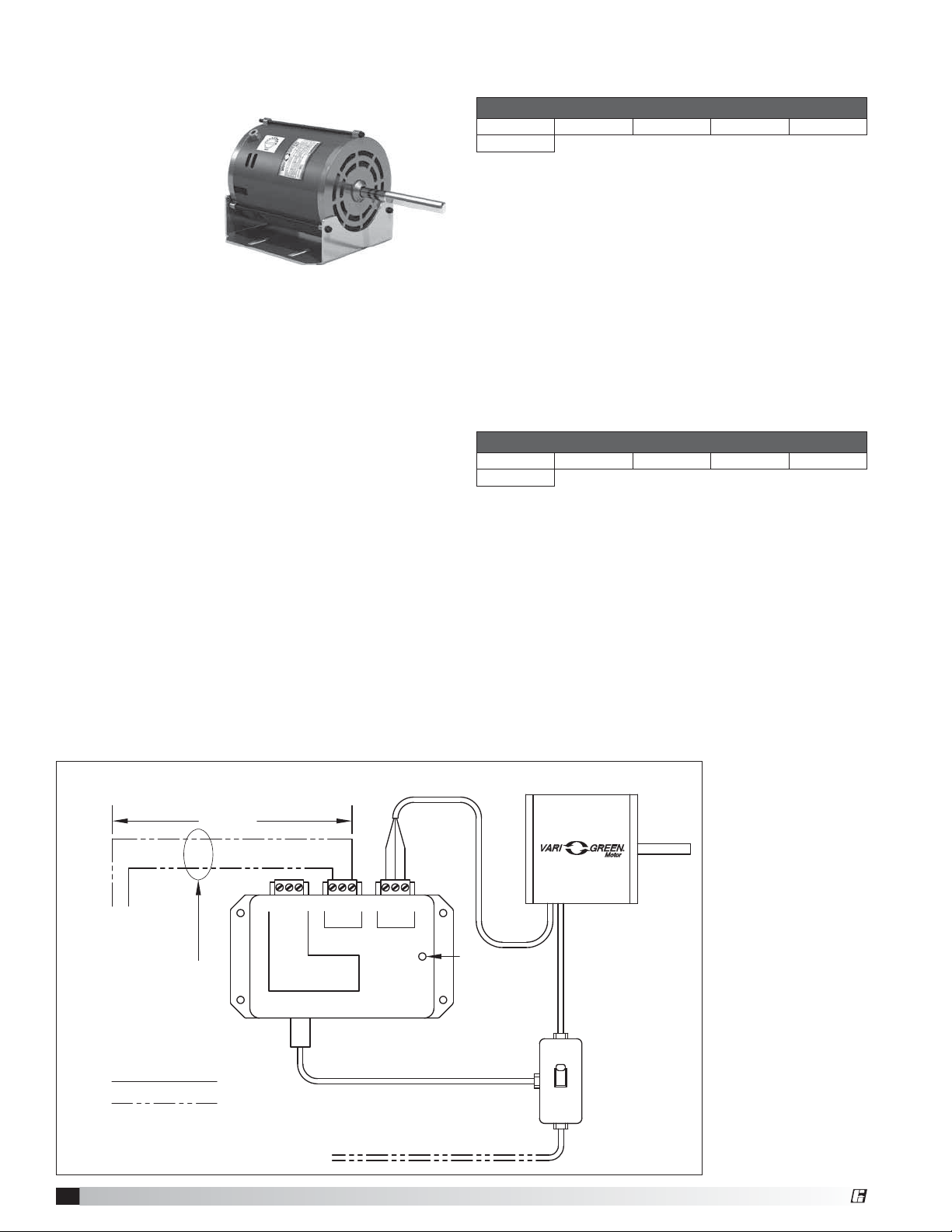
transformer is available to supply this voltage. See Fig. 1
The motor is pre-wired at the factory and cannot be
changed inside the motor. Connect single-phase power
at the voltage listed on the nameplate, along with the
0-10 VDC and 24V signal for speed control.
NOTE: The motor will not operate without the proper
control voltages.
Operation and Wiring
- 0-10V Input Only
Part Numbers Covered in this Section
309028 309029 310108 310475 310476
311353
100 ft. or less
White
Black
Red
COM
24V
0-10V
COM
24V
0-10V
N.C.
COM.
N.O.
Control
Motor
TRANSFORMER
Trip Point = 1.85VDC
Contact Rating:
10A @ 24-240VAC
5A @ 30VDC
Auxiliary
Contact
TO REMOTE DEVICE
PROVICED BY
OTHERS
Low voltage, route away
from high voltage lines
and/or use shielded cable
Factory Wiring
Field Wiring
115/230 VAC input
to match motor name plate
Green indiator light
—Power present
2 x 4
Junction
Box
Transformer Assembly
Fig. 1 0-10 VDC External connection with factory mounted transformer
®
3
Vari-Green Motor and Controls
These motors have both a potentiometer dial on the
motor for speed adjustment AND have the ability to
accept a 0-10 VDC signal for remote speed control.
There is a 4 second delay between the application of
power and the motor starting.
The motor is pre-wired at the factory and cannot be
changed inside the motor. Connect single-phase power
at the voltage listed on the nameplate. If remote control
is desired, connect the 0-10 VDC and 24V signal for
remote speed control.
Dial on motor – A small screwdriver can be used to
make the speed adjustment. To increase the speed,
rotate the dial clockwise. To decrease the speed, rotate
the dial counter clockwise. There is no need to connect
the control wires.
0-10 VDC signal – The dial on the motor must be
rotated fully clockwise to achieve the full speed range.
If this is not done, the dial will act as a maximum
speed limiter.
From 0-1.9V, the motor will be off, and will operate in
the 2-10V range. 24 VAC/DC power is also required for
operation. The motor will consume 0.7VA at 24 VAC
or 25mA at 24 VDC. A factory mounted transformer is
available to supply this voltage. See Fig. 1
Part Numbers Covered in this Section
310359 311731 311377 311388 311812
312359 312360 312361 312362 312619
313233 313234 313235 313712 313713
313714 313715 314534 314945
Operation and Wiring
- Potentiometer Dial and 0-10V Input
Low Voltage Harness Part Numbers
Type Use with Motor 18 in. long 36 in. long
3-pin 311731, 310359 384431 384432
9-pin
312359, 311377,
311812, 311388,
312360, 312361,
312362, 312619,
313233, 313234,
313235, 313712,
313713, 313714,
313715, 314534,
314945
384804 384805
0-10V Analog input connection
Red + 0-10 VDC
White Common*
Black +24 VAC/DC
* Common is shared between both 24V power
and 0-10V signal.
The impedance of 0-10V circuit is 12KΩ
Factory Mounted Transformer (Fig. 1)
A factory mounted transformer is available to
supply 24 VDC power to the motor when the
0-10V signal is by others. This transformer has
the capability to power a remote device if desired.
The power available to a remote device is 400mA
at 24 VDC. If the remote device is powered by
a different source, connect the analog output to
the 0-10V and COM terminals of the transformer.
This will pass the signal through to the motor.
WARNING
Do not connect an external 24V supply to the
transformer's control terminal labeled 24V. If the
external device providing the 0-10V signal is powered
elsewhere, this terminal can remain unused.
Troubleshooting
Motor does not operate
1. Check all wiring connections to ensure they are
correct and secure.
2. Verify that all voltages are present at the motor,
including 24V and 0-10 VDC, if applicable.
3. Make sure that the fan wheel will rotate freely and
there are no foreign objects in the wheel. If fan wheel
does not rotate freely, disconnect power from the
motor and adjust the wheel or housing until the
wheel can freely rotate. Apply power and the motor
should restart.
4. If motor has both the dial on the motor and 0-10VDC
control option, control wiring issues can be tested
by disconnecting the control wires from the motor.
The motor should then operate using the dial on the
motor for speed control.
Motor will not reach maximum speed
1. Make sure dial is rotated full clockwise, if applicable.
2. Make sure motor is receiving 10 VDC, if applicable.
NOTE
The 9-pin connector on the motor contains 6 wires.
The red, black and white wires are used for the
external control signal and the other three are used for
factory initialization and programing.
A low voltage wiring harness is needed to supply the
0-10V signal to the motor. This harness is available from
the factory if conversion is necessary.
3. There are some motor/fan combinations
where the motor may not reach nameplate
RPM. See Max RPM table on page 10 for the
maximum motor speed for your application.
®

4
Vari-Green Motor and Controls
Wiring
1. All high and low voltage wiring connections are made
inside the motor control box at the factory. Normally,
there is no reason to enter the control box of the
motor. If there is a need to enter the control box,
disconnect power and wait at least five minutes to
allow the capacitors to discharge.
2. The motors are factory wired for the ordered voltage.
If the factory wired voltage does not match the
desired voltage, the voltage can be changed, with
exception of the 2HP motor (310420), which is
208-240V only.
115V: Connect 115 VAC to L1, connect Neutral to N.
The L2 terminal remains empty. Connect ground to
grounding stud.
208-240V - Connect Line voltage to L1 and L2. The
N terminal remains empty. Connect the ground to the
grounding stud.
Part Numbers Covered in this Section
310420 311156
Features
Speed control -
These motors can
be controlled by
either a dial on the
motor or a 0-10 VDC
signal for remote control.
Soft start – All motors feature soft-start technology
which eliminates inrush current at start-up. The motors
will reliably start at any speed setting. There will be up
to a 30 second delay between the application of power
and the motor starting. The motor will "rock" back and
forth upon startup as part of its normal operation.
Overload protection – If the motor becomes
overloaded, it will automatically shut itself down. The
maximum programed motor speeds have been selected
to prevent this from happening in normal operation.
Locked rotor protection – If the motor encounters a
locked-rotor scenario, it will automatically shut itself
down. It will try to restart up to 3 times, and if after the
3rd time the motor will still not rotate, the motor will not
attempt to start again until power is cycled.
Thermal protection – The motors have an automatic
reset thermal protector. This is meant to protect the
motor from a severe temperature rise.
RPM measurement – The motor RPM can be
measured by removing the cooling fan cover and using
a contact or optical tachometer. Be sure to replace the
cooling fan cover when finished.
Reversible rotation – The motor direction has been
pre-set at the factory for the rotation of the fan but can
be reversed if necessary.
Operation and Wiring
These motors can be controlled by either a dial on the
motor or a 0-10 VDC signal for remote control. The
motor will be supplied from the factory with the correct
accessory depending on what was ordered.
Dial on Motor - Turn the dial with your fingers to adjust.
To increase the speed, rotate the dial clockwise. To
decrease the speed, rotate the dial counter clockwise.
Turning the dial full CCW will turn the motor off.
0-10 VDC Signal - From 0-1.9V, the motor will be off,
and will operate in the 2-10V range. This motor does not
require 24V power for operation.
115V Connection inside control box
208-240V Connection inside control box
0-10V Analog input connection
Red + 0-10 VDC
White Ground
®
 Loading...