


Part #474645
Model PVF and PVG
Indirect Gas-Fired Heat Modules
Installation, Operation and Maintenance Manual
Please read and save these instructions for future reference. Read carefully before attempting to assemble, install, operate or maintain the product described. Protect yourself and others by observing all safety information. Failure to comply with instructions could result in personal injury and/or property damage!
Recognized Component
Model PVF
Model PVG
General Safety Information
These indirect gas-fired furnaces are commonly used in many different manufacturer’s ventilating products. For unit-specific information, refer to the Installation, Operation and Maintenance manual (IOM) for the unit in which this furnace is installed.
•Both the furnace units are listed for installation in the United States and in Canada.
•Installation of gas-fired duct furnaces must conform with local building codes. In the absence of local building codes, installation must conform to the National Fuel Gas code, ANSI Z223.1 or in
Canada, CAN/CGA-B149 Installation codes.
•All electrical wiring must be in accordance with the regulations of the National Electric Code, ANSI/ NFPA-70.
•Unit is approved for installation downstream from refrigeration units. In these conditions, condensate could form in the duct furnace and provision must be made to dispose of the condensate.
FOR YOUR SAFETY
If you smell gas:
1.Open windows.
2.Do not touch electrical switches.
3.Extinguish any open flame.
4.Immediately call your gas supplier.
FOR YOUR SAFETY
The use and storage of gasoline or other flammable vapors and liquids in open containers in the vicinity of this appliance is hazardous.
WARNING
Improper installation, adjustment, alteration, service or maintenance can cause injury or death. Read the installation, operating and maintenance instructions thoroughly before installing or servicing this equipment.
Indirect Gas-Fired Heat Modules 1
NOTE
This unit is an indirect gas-fired heat module that will be referred to in this manual as a furnace.
Receiving
Since this furnace is already installed in a ventilation unit, follow the Receiving Instructions for the unit which are provided in the unit-specific Installation, Operating and Maintenance manual (IOM).
Unpacking
If unit is to be installed, tested and operated right away, locate and remove all packing materials from the furnace, including any protective coverings that may be on the combustion air intake and on the furnace exhaust. Follow Unpacking Instructions as found in the unit-specific IOM.
Storage
If unit must be stored after it is received, follow the unit-specific storage instructions found in the unit IOM. Also plug all piping.
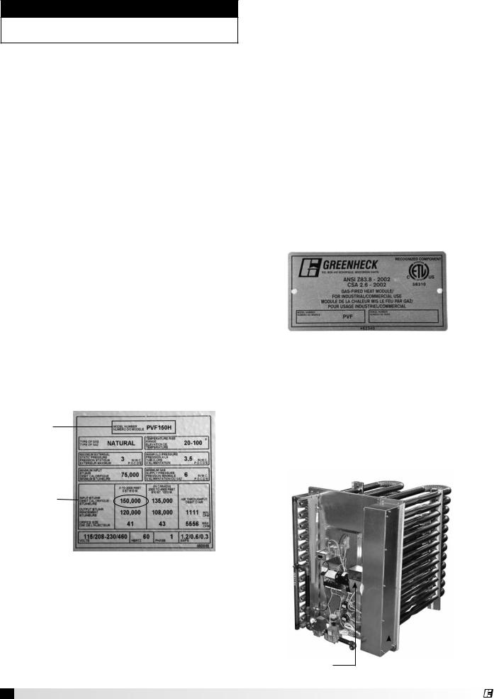
Unit Identification
It is necessary to know the unit model number, the burner control turndown and the serial number. This information is needed when ordering replacement parts and is available on labels located on the unit.
Furnace Model Number
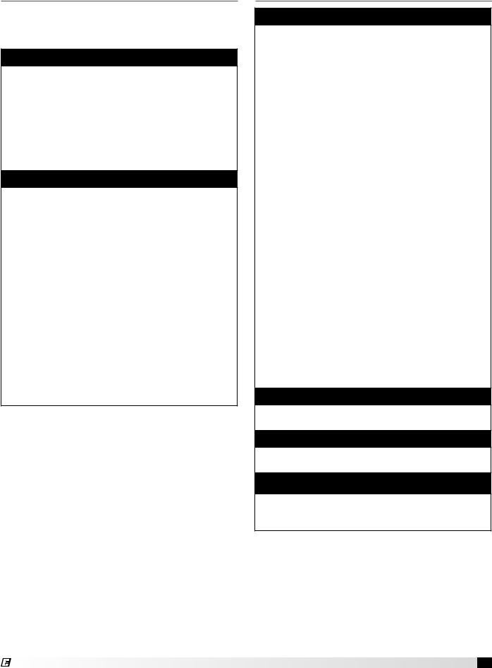
On the furnace access door or immediately next to the door is a Mylar data label. See image below. Locate the furnace model number at the top of the label and record it here:
Furnace Model Number: _____________________
Model
Number
Minimum Input
BTU/HR 
Input
BTU/HR
Typical Furnace Data Label
2 Indirect Gas-Fired Heat Modules
Burner Control Turndown
Burner turndown ratio is used in many places and must be calculated. On the data label, locate the
INPUT BTU/HR (the largest number on the label) and also the MINIMUM INPUT BTU/HR. Calculate the burner turndown ratio and record it.
INPUT BTU/HR |
= |
Burner Control |
||
MINIMUM BTU/HR |
Turndown Ratio |
|||
Example: |
150,000 |
= |
2 |
|
75,000 |
||||
|
|
|
||
The turndown ratio is 2:1 in this example.
Burner Turndown: _______________
Furnace Serial Number
The furnaces are assigned the same serial number as the main ventilating unit. On the main unit control access door is a stamped metal plate identifying the unit serial number. Record that information here.
Furnace/Unit Serial Number: _____________________
Typical Unit ID Plate
ETL Listing
Model PVF and PVG furnaces have been ETL tested as gas-fired heat modules intended for installation as a component within heating equipment in duct or cabinet mounted applications. They are ETL Recognized Components.
Product Overview
Burner |
|
Heat |
||||||
Assembly |
Exchangers |
|||||||
|
|
|
|
|
|
|
|
|
|
|
|
|
|
|
|
|
|
|
|
|
|
|
|
|
|
|
|
|
|
|
|
|
|
|
|
 Collector
Combustion Box
Blower
®

Table of Contents
General Safety Information. . . . . . . . . . |
. |
1 |
|
Receiving, Unpacking, Storage. . . . . . . . . |
|
2 |
|
Unit Identification. . . . . . . . . . . . . . . 2 |
|||
Furnace Model Number. . . . . . . . . . . . |
|
2 |
|
Burner Control Turndown . . . . . . . . . . . |
|
2 |
|
Furnace Serial Number . . . . . . . . . . . . |
|
2 |
|
ETL Listing. . . . . . . . . . . . . . . . . |
|
2 |
|
Product Overview . . . . . . . . . . . . . . |
|
|
2 |
Furnace Control Center |
|
|
|
Furnace Control Center Components . . . . . |
. 4 |
||
Typical Furnace Control Logic . . . . . . . . |
. |
4 |
|
Typical Furnace, Electrical and |
|
|
|
Control Components. . . . . . . . . . . . . . . . |
. . . . . . |
. |
5 |
Gas-Fired Burner Turndown . . . . . . . . . |
|
6 |
|
Electronic Modulation. . . . . . . . . . . . |
|
6 |
|
Two Stage Valve. . . . . . . . . . . . . . |
|
|
6 |
Combinations . . . . . . . . . . . . . . . |
|
|
6 |
Available Turndown Control Options. . |
. . . |
. 6 |
|
Installation of Venting for Outdoor Units . . . . 7
Installation of Venting for Indoor Units. . . . . 7 Venting Methods. . . . . . . . . . . . . . 8
Installation of Standard Indoor Venting
Horizontal.. . . . . . . . . . . . . . . . 8 Vertical. . . . . . . . . . . . . . . . . . 8
Installation of Concentric Venting
Horizontal.. . . . . . . . . . . . . . . 9-10 Vertical. . . . . . . . . . . . . . . . . 10-11
Two-Pipe Venting - Horizontal . . . . . . . 11-12 Two-Pipe Venting - Vertical. . . . . . . . . . 12
Installation of Control Wiring . . . . . . . . 13 Installation of Discharge Air Sensor. . . . . 13
Installation of Gas Piping.. . . . . . . . 13-14
Gas Supply Requirements. . . . . . . . . . . . . . . . . . . 14 Connect the Supply Gas Line. . . . . . . . . 14 Installation Addition Regulator. . . . . . . . 14 Testing the System for Leaks. . . . . . . . . 14 Gas Pressure Test Ports. . . . . . . . . . . 14
Sequence of Operation. . . . . . . . . . |
15 |
Start-Up / Standby . . . . . . . . . . . . |
. 15 |
Heat Mode. . . . . . . . . . . . . . . . |
15 |
Recovery from Lockout.. . . . . . . . . . |
15 |
Performance Data. . . . . . . . . . . |
. |
. |
|
15 |
Gas Valves.. . . . . . . . . . . . . . |
. |
. |
|
16 |
Start-Up - Furnaces (all units). . . . . . . |
|
|
|
17 |
4:1 Turndown Electronic Modulation. . . |
. |
. |
. |
17 |
Adjust High Fire and Low Fire Settings.. |
. |
. |
|
18 |
Modulating Valve High Fire Setting. . . |
. |
. |
. |
18 |
Modulating Valve Low Fire Setting . . . |
. |
. |
. 18 |
|
2:1 Turndown Electronic Modulation. . . |
. |
. |
. 19 |
|
8 Stage Combustion. . . . . . . . . . |
. |
. |
|
20 |
Single Stage.. . . . . . . . . . . . . |
. |
. |
|
20 |
2 Stage Combustion. . . . . . . . . . |
. |
. |
|
21 |
Combination Turndown Configurations. . |
. |
. |
. 21 |
|
Troubleshooting |
|
|
|
|
Ignition Controller . . . . . . . . . . . |
. |
. |
|
22 |
4:1 Electronic Modulation. . . . . . . . |
. |
23-24 |
||
2:1 Electronic Modulation. . . . . . . . |
. |
. |
|
25 |
8 Stage. . . . . . . . . . . . . . . . . 26-27 |
||||
Single and Two Stage. . . . . . . . . |
. |
. |
. |
28 |
Reference: FX Controller. . . . . . . . |
. |
. |
|
29 |
Program Mode. . . . . . . . . . . . . . . 29 |
||||
Inlet Air Sensor (optional). . . . . . . . |
. |
. |
|
29 |
Discharge Air Temperature. . . . . . . |
. |
. |
. |
29 |
Outside Air Temperature. . . . . . . . |
. |
. |
. |
30 |
Field Adjustments |
|
|
|
|
Go to High Fire Mode. . . . . . . . . |
. |
. |
|
30 |
Return to Normal Operation . . . . . . . . |
|
|
|
30 |
Access to Set Points Menu. . . . . . |
. |
. |
. 30 |
|
Access the Discharge Air Temperature. . . . 30 |
||||
Access the Inlet Air Sensor (optional). . . . . 30 |
||||
Access the Room Override Setting. . . |
. |
. |
. 30 |
|
Maintenance |
|
|
|
|
Combustion Blower Motor. . . . . . . |
. |
. |
. |
31 |
Burners and Orifices. . . . . . . . . . |
. |
. |
|
31 |
Heat Exchanger. . . . . . . . . . . . |
. |
. |
|
31 |
Flue Collector Box.. . . . . . . . . . |
. |
. |
|
31 |
Electrical Wiring.. . . . . . . . . . . |
. |
. |
|
31 |
Gas Train . . . . . . . . . . . . . . . . . 31 Replacement Parts . . . . . . . . . . . . . 31
Maintenance Log. . . . . . . . . . .Backcover
Warranty . . . . . . . . . . . . . . Backcover
Indirect Gas-Fired Heat Modules 3
®
Furnace Control Center
Each ventilating unit containing a furnace or a pair of furnaces will have a furnace control center located on the furnace vest plate. The control center receives high voltage AC from the main unit control center and in most cases, also receives low voltage control
signals (call for heat) from the main unit control center. In all cases, see the unit-specific wiring schematic located inside the main control center door.
Furnace Control Center Components
(Components and their locations will vary.)
Components shown are for a typical 4:1 turndown electronic modulation configuration.
13 |
|
|
|
|
10 |
|
|
|
|
5 |
|
|
3 |
14 |
4 |
2 |
|
||
|
|
|
||
|
6 |
|
8 |
|
|
|
1 |
|
|
7 |
|
|
|
|
6a |
|
|
|
|
|
|
9 |
|
|
|
12 |
|
11 |
|
High Voltage Side
1.Power Distribution Block
2.Inducer Relay (controls combustion fan)
3.Combustion Blower
Low Voltage Side
4.Input Converter
5.FX Controller (modulates heat and switches entire unit on/off
6.Spark Generator (also has high voltage present) 6a. Spark Igniter
7.24 volt Terminal Strip
Control Sensors
8.High Temperature Sensor (auto reset)
9.Airflow Switches
10.Flame Sensor
Gas Train
11.Combination Valve
12.Modulating Valve
13.Burner Manifold
14.Collector Box
4 Indirect Gas-Fired Heat Modules
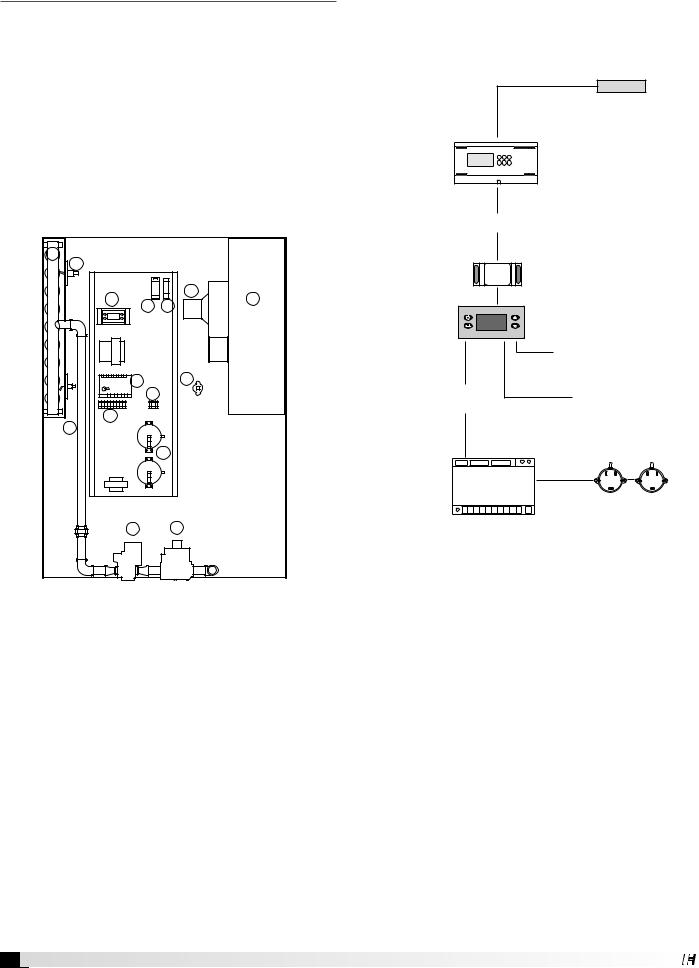
Typical Furnace Control Logic
In all cases, refer to the unit-specific wiring diagram located on the unit control center door.
This illustration is only for a typical 4:1 turndown electronic modulation configuration
Temperature Sensor
If there is no DDC, the sensor is connected to the FX.
DDC |
|
|
Located in |
|
|
unit main |
(optional) |
|
control center |
||
|
||
|
Call for heat |
|
JOHNSON |
|
Input Converter |
CONTROLS |
|
|
(optional) |
|
FX Controller |
|
|
|
|
Activates and modulates |
|
|
Modulating Valve |
Activates |
|
Controls Speed |
Ignition Controller |
of Combustion |
|
|
|
Blower |
Ignition
Controller
|
|
|
|
|
|
Activates |
|
|
|
|
|
|
|
|
|
|
|
|
|
Combustion Blower |
Activates |
|
|
|
|
Spark to Igniter |
|
|
|
|
|
|||
Combination Valve
1.DDC (if present) senses low temperature on temperature sensor, sends 10 VDC signal to signal input converter.
2.Input converter changes analog signal to a form that can be read by the FX controller and sends the signal to the FX controller (call for heat).
3.FX controller receives call for heat, activates modulating valve and the ignition controller.
4.Ignition controller receives call for heat from FX controller, sends spark to igniter and activates the combination valve. It looks for verification that the combustion blower is running.
5.Flame sensor (10, right) detects flame and ignition controller shuts off igniter.
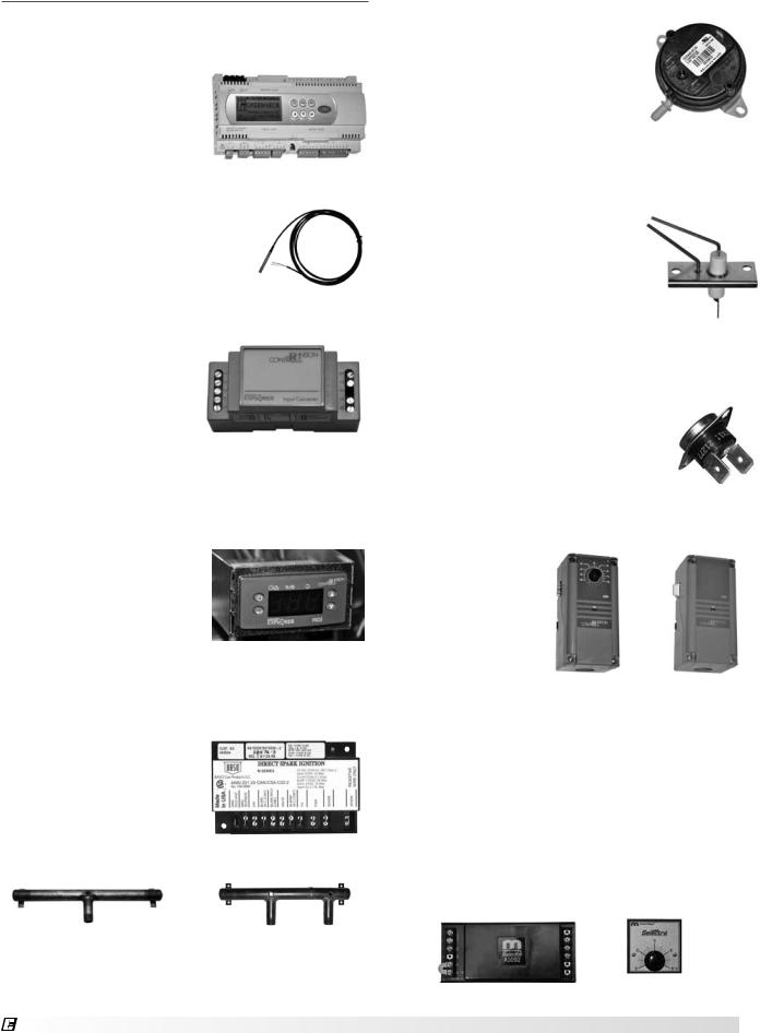
Typical Furnace, Electrical and
Control Components
DDC
The DDC provides the call for heat to the ignition controller and also monitors the discharge air temperature. It is found
only in the unit main control center. On units with electronic modulation, it also determines the required burner firing rate.
Discharge Air Temp Sensor
This sensor is shipped with all units and must be field-installed in the discharge air duct. If the ventilating unit has a DDC controller, a second sensor is included.
Input Converter
The input converter takes an analog signal from a
DDC or a BMS and converts it to a control signal that can be used by the FX programmable controller.
It is found in the furnace control center.
FX Programmable Controller
Used on all 4:1 electronic modulating controls and
8:1 staged turndown.
The FX controller turns on and electronically modulates gas valves. It will also enable the ignition module. The FX controller
has a digital readout and four push buttons, one for Function, one for Enter and two for scrolling up or down. It is pre-programmed at the
factory for each specific furnace configuration and it may be used to control two furnaces at the same time.
Ignition Controller
This controller is found only in the furnace control center. It has an LED indicator
light on the top right of the controller that will flash GREEN for normal operation or RED for an error. Some furnace configurations have two of these controllers.
Burner Manifold
Single Section |
Split Burner |
Burner Manifold |
Manifold |
®
Airflow Switch
Airflow switches are used on both furnaces and are found on the furnace vest plate. If the combustion blower is multi-speed, there will be
two of them and each will switch in response to a different pressure. The switch is connected to the combustion blower by means of a vacuum tube and is used to sense
operation of the combustion blower.
The internal switch is Normally Open (NO). If the blower fails to operate, the open circuit will cause the ignition controller to disable the furnace.
Flame Igniter
The igniter receives a high voltage input from the ignition controller to produce a spark between the two electrodes. It operates only during the ignition phase. On split burner manifolds, there will be two igniters.
Flame Sensor
The flame sensor is identical to the flame igniter. It is located on the opposite end of the burner manifold from the igniter.
Auto Reset High Temperature Limit Switch
This limit switch is installed through the vest plate into the supply air plenum.
A350 and S350 Control System
Used on two stage and single stage controls. Used in conjunction with a field-installed remote temperature sensor. Has an
LED indicator light to show when the output relay is energized. When used with multiple furnaces, the S350 controller is used for the second furnace.
1092 Control System
Used on 2:1 electronic modulating controls. The
A1092 control system consists of an amplifier, a remote temperature dial and a remote temperature sensor. The amplifier and remote temperature dial are factory-installed on the vest plate while the remote temperature sensor must be field-installed. The temperature dial and amplifier are installed in the furnace control center. Field adjustments include discharge air temperature, which is done by means of the Remote Temperature Dial.
Amplifier |
Remote |
|
Temperature Dial |
||
|
|
|
|
Indirect Gas-Fired Heat Modules |
5 |
Gas-Fired Burner Turndown
Furnaces are available in single stage, multi-stage or electronically modulated configurations. In single stage, the entire furnace is either on or off. In multistage furnaces, combustion occurs in stages and is
expressed as the number of different stages (example: 8 stage). Electronically modulated furnaces have continuously variable firing rates. In both staged and electronically modulated furnaces, the result is burner turndown. Turndown is the capability of the furnace to operate at less than full capacity, accomplished
by reducing the amount of gas flow when the unit is operating. The advantage in being able to turn down firing rate is that when the demand for heat is low, the furnace will not cycle as often. Turndown is expressed as a ratio and is found by dividing the maximum BTU input by the minimum BTU input.
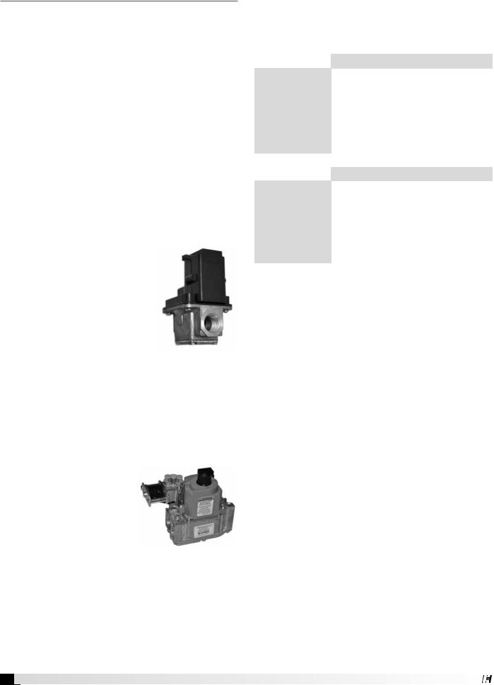
Electronic Modulation
Turndown is specified by the customer. Most common is the use of an electronically-controlled gas valve which provides a 4:1 turndown. The entire furnace
is sized appropriately for the maximum heat output ordered by the customer, but it can operate at the same efficiency at only 25% of its maximum capacity. The electronically-controlled gas valve will modulate the combustion rate continuously, dependent on the output from an FX controller. With this method, all the burners fire
at the same time but at a varying
capacity. The Modulating Valve is used in conjunction with an FX electronic controller and a combination valve which provides an ON/OFF function.
Two Stage Valve
The two-stage valve is switched electrically from closed to full output to half output, producing a 2:1 turndown. In some cases, multiple furnaces may be used in a ventilating unit. When this is done with two single-stage furnaces,
it is possible to run just one furnace at a time, resulting in a 2:1 turndown. If each furnace is already configured for a 2:1 turndown, the overall result can then be a 4:1 turndown.
Combinations
Various combinations of the methods outlined may be used to accomplish the turndown requested by the customer.
Available turndown control options include:
|
Electronic Modulation |
|
|
|
4:1 uses modulating valve and FX |
Single Furnace |
programmable controller |
Unit |
2:1 uses modulating valve and |
|
1092 control system |
|
|
|
8:1 uses one 4:1 modulating furnace with |
Two Furnace |
FX controller and one 2 stage furnace |
Unit |
4:1 uses two 4:1 modulating furnaces |
|
running in parallel |
|
|
|
Staged |
|
|
|
|
Single Furnace |
8 stage |
|
|
||
2 stage |
||
Unit |
||
|
||
1 stage |
||
|
||
|
|
|
|
16 stage uses one 8 stage furnace and |
|
Two Furnace |
one single-stage furnace |
|
Unit |
4 stage uses two 2 stage furnaces |
|
|
2 stage uses two single-stage furnaces |
|
|
|
6 Indirect Gas-Fired Heat Modules
Installation of Venting for
Outdoor Units
Follow Guidelines
All of the following guidelines must be followed when installing the unit.
WARNING
Do not install units in locations where flue products can be drawn into adjacent building openings such as windows, fresh air intakes, etc. Distance from vent terminal to adjacent public walkways, adjacent buildings, operable windows and building openings shall conform with the local codes. In the absence of local codes, installation shall conform
with the National Fuel Gas Code, ANSI Z223.1 or the
Canadian CAN/CGA B-149 Installation Codes.
WARNING
The following guidelines must be followed for all outdoor units:
1.Building materials that will be affected by flue gases should be protected.
2.Maintain minimum horizontal clearance of 4 feet from electric meters, gas meters, regulators and relief equipment. In Canada, the minimum clearance is 6 feet.
3.The combustion blower discharge on outdoor units must be located a minimum of 42 inches from any combustible materials.
4.Do not modify or obstruct the combustion air inlet cover or the combustion blower weatherhood.
5.Do not add vents other than those supplied by the manufacturer.
6.During the winter, keep the unit clear of snow to prevent any blockage of the combustion venting.
Install Stack (optional)
Clearance may require an exhaust stack. Install an exhaust stack as needed to the exhaust connection on the unit. Install a vent terminator on the exhaust pipe.
Exhaust transition and vent termination must be purchased from the factory for proper operation. Exhaust pipe is by others.
Installation of Venting for
Indoor Units
Warning
The following guidelines must be followed for all indoor units:
1.Installation of venting must conform with local building codes. In the absence of local codes, installation must conform with the National Fuel Gas Code, ANSI Z223.1 or in Canada, CAN/
CGA-B149 installations codes.
2.For the exhaust pipe, use pipe approved for a Category III appliance or single wall, 26 gauge or heavier galvanized vent pipe. The piping is required to be gas-tight by ANSI.
3.For the combustion air pipe on separated combustion units, sealed single-wall galvanized air pipe is recommended.
4.The joints must be sealed with a metallic tape or
Silastic™ suitable for temperatures up to 350°F.
5.A minimum of 12 inches of straight vent pipe is recommended after the exhaust connection and before any elbows.
6.Vertical combustion air pipes should be fitted with a tee, drip leg and clean-out cap to prevent any moisture in the combustion air pipe from entering the unit.
7.To reduce condensation, insulate any vent runs greater than 5 feet.
8.All vent pipe connections should be made with at least three corrosion-resistant sheet metal screws.
9.Refer to the National Fuel Gas Code for additional piping guidelines.
Note
Vent piping is supplied by others and not supplied by manufacturer.
Note
The drip leg should be cleaned out periodically during the heating season.
Note
Clearances from combustible material for indoor units are determined by the National Fuel Gas Code and/or other local codes.
Indirect Gas-Fired Heat Modules 7
®
Venting Methods
There are three venting methods for indoor mounted units. For each method, the units can be vented horizontally through an exterior wall or vertically through the roof. Specific venting instructions are provided for each method and shown in the following pages. Construct the vent system as shown in these instructions. Refer to your unit specific submittal to determine the applicable venting option.
The venting method options are:
Standard Indoor Venting
•uses building air for combustion
•vents exhaust to outdoors
•one exterior roof or wall penetration
Separated Combustion Concentric Venting
•uses outside air for combustion
•vents exhaust to outdoors
•one exterior roof or wall penetration
Separated Combustion 2-Pipe Venting
•uses outside air for combustion
•vents exhaust to outdoors
•two exterior roof or wall penetrations
Note
For each method, the units can be vented horizontally through an exterior wall or vertically through the roof. Refer to the specific venting instructions for your unit. Construct the vent system as shown in these instructions.
Installation of Standard Indoor
Venting
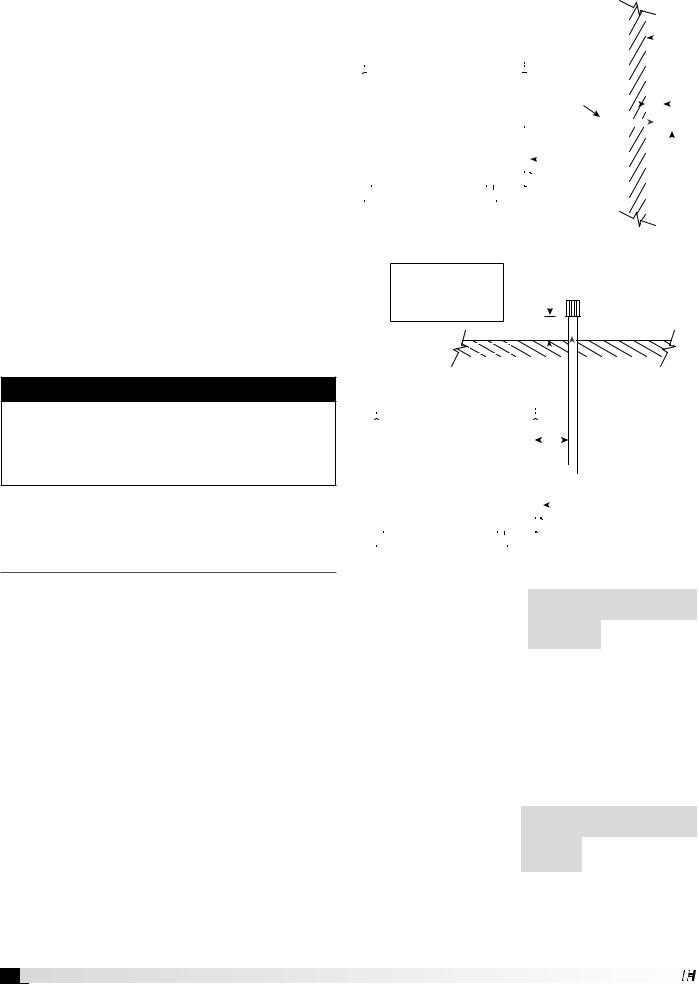
Standard indoor venting uses one penetration through an exterior wall or roof for venting the flue exhaust. The combustion air is supplied from the air inside the building. Units must not be installed in a potentially explosive, flammable, or corrosive atmosphere. To prevent premature heat exchanger failure, do not locate unit where chlorinated, halogenated or acid vapors are present.
When units are installed in tightly sealed buildings, provisions should be made to supply an adequate amount of infiltration air from the outside. The rule of thumb is that an opening of one square inch should be provided for every 1000 BTUs per hour of input rating.
Vent terminals must be used. Construct the vent system as shown in the drawings. Reference the Vent Pipe Diameter table and Exhaust Vent Pipe table for additional details.
|
|
|
|
|
|
|
|
|
|
|
|
|
|
|
|
Exterior |
||||||
|
|
|
|
|
|
|
|
|
|
|
|
|
|
|||||||||
|
|
A = 12 inch minimum |
|
|
|
|
|
|||||||||||||||
|
|
|
|
|
|
|
|
|
|
|
|
|
|
|
|
|
|
Wall |
||||
|
|
|
|
|
Pitch vent pipe |
|
|
|
|
|
||||||||||||
|
|
|
|
|
|
|
|
|
|
|
||||||||||||
|
|
|
|
|
|
|
|
|
|
|
|
|
|
|
|
|||||||
|
|
|
|
|
|
|
|
|
|
|
|
|
|
|
|
|||||||
|
|
|
|
|
|
|
|
|
|
|
|
|
|
|
|
|||||||
|
|
|
|
|
downward |
|
|
|
|
|
|
|
|
|
|
|
||||||
|
|
|
|
|
from furnace |
|
|
|
|
|
|
|
|
|
|
|
||||||
|
|
|
|
|
¼ inch per foot |
|
|
|
|
A |
|
|
|
|
|
|||||||
|
|
|
|
|
|
|
|
|||||||||||||||
|
|
|
|
|
|
|
|
|
|
|
|
|
|
|||||||||
|
|
|
|
|
|
|
|
|
|
|
|
|
|
|
|
|
|
|
|
|
|
|
|
|
|
|
|
|
|
|
EXHAUST |
|
|
|
|
|
|
|
|
|
|
|
|
||
|
|
|
|
|
|
|
|
|
|
|
|
|
|
|
|
|||||||
|
|
|
|
|
|
|
|
Air Inlet |
|
|
|
|
|
|
|
|
|
|
|
|||
|
|
|
|
|
|
|
|
|
|
|
|
|
|
|||||||||
|
|
|
|
|
|
|
|
|
|
|
|
Exhaust |
||||||||||
|
|
|
|
|
|
|
|
|
|
|
||||||||||||
|
|
|
|
|
|
|
|
|
|
|
|
|
|
|
|
Vent |
||||||
|
|
|
|
|
|
|
|
|
|
|
|
|||||||||||
|
|
|
|
|
|
|
|
|
|
|
|
|
|
|
|
Terminal |
||||||
|
|
|
|
|
|
|
|
|
|
|
|
|
|
|
|
|
|
|
|
|
|
|
|
|
|
|
|
|
|
|
|
|
|
|
|
|
|
|
|
|
|
|
|
|
|
|
|
|
|
|
|
|
|
|
|
|
|
|
|
|
|
|
|
|
|
|
|
|
|
|
|
|
|
|
|
|
|
|
|
|
|
|
|
|
|
|
|
|
|
|
|
Standard Indoor Venting - Horizontal
A = 12 inch minimum
B = 12 inch minimum, but should size
according to expected
snow depth 
 Exhaust Vent Terminal
B
|
|
|
|
Roof Line |
|
|
|
|
|
|
|
|
|
|
|
|
|
|
|
|
|
|
|
|
|
|
|
|
|
|
|
|
|
|
|
||||
|
|
|
|
|
|
|
|
|
|
|
|
|
|
|
|
|
|
|
|
|
|
|
|
|
|
|
|
|
|
|
|
|
|
|
|
|
|||
|
|
|
|
|
|
|
|
|
|
A |
|
EXHAUST |
|
|
|||||
|
|
|
|
|
|
|
|
|
|
||||||||||
|
|
|
|
|
|
|
|
|
|
||||||||||
|
|
|
|
|
|
|
|
|
|
|
|
|
|
|
|||||
|
|
|
|
|
|
|
|
|
|
|
|
|
|
|
|||||
|
|
|
|
|
|
|
|
|
|
|
|
|
|||||||
|
|
|
|
|
|
|
|
|
|
|
|
|
|
|
|
|
|||
|
|
|
|
|
|
|
|
|
|
|
|
|
|
|
|
|
|
|
|
|
|
|
|
|
|
|
|
|
|
|
|
Air Inlet |
|
|
|||||
|
|
|
|
|
|
|
|
|
|
|
|
|
|
||||||
|
|
|
|
|
|
|
|
|
|
|
|
|
|
||||||
|
|
|
|
|
|
|
|
|
|
|
|
|
|
|
|
|
|
|
|
|
|
|
|
|
|
|
|
|
|
|
|
|
|
|
|
|
|
|
|
|
|
|
|
|
|
|
|
|
|
|
|
|
|
|
|
|
|
|
|
|
|
|
|
|
|
|
|
|
|
|
|
|
|
|
|
|
|
|
|
|
|
Standard Indoor Venting - Vertical |
|||||||||||||||||
Vent Pipe Diameter |
|
|
|
|
|
|
|
|
|
|
|
|
|
||||||
Furnace Size |
Exhaust Pipe |
||||||||||||||||||
Select the vent pipe |
|
|
|
(MBH) |
Diameter (inches) |
||||||||||||||
diameter. Use only the |
75-175 |
4 |
|
||||||||||||||||
specified pipe diameter. |
200-400 |
6 |
|
||||||||||||||||
Installing Exhaust Vent Pipe
Install the vent pipe with a minimum downward slope
(from the unit) of 1/4-inch per foot (horizontal venting only). Securely suspend the pipe from overhead structures at points no greater than 3 feet apart.
The minimum vent length is 5 feet for horizontal and 10 feet for vertical. The maximum vent length is 70 feet. The total equivalent vent length must include
elbows. The equivalent |
|
|
|
|
Vent |
Minimum |
Maximum |
||
length of a 4 inch |
||||
Length |
(feet) |
(feet) |
||
elbow is 6 feet and the |
||||
|
|
|
||
Horizontal |
5 |
70 |
||
equivalent length of a |
||||
|
|
|
||
Vertical |
10 |
70 |
||
6 inch elbow is 10 feet. |
||||
|
|
|
||
|
|
|
Attach the vent terminal to the end of the exhaust pipe.
8 Indirect Gas-Fired Heat Modules
Installation of Concentric Venting
Concentric venting allows the exhaust pipe and combustion air pipe to pass through a single hole in the roof or wall of the building. A concentric venting adapter (CVA) is required for concentric venting.
The concentric venting adapter is designed for indoor installations and should never be installed on the exterior of the building.
The exhaust pipe must terminate with the vent terminal. For horizontal venting, the combustion air pipe must terminate with the combustion air guard. For vertical venting, the combustion air pipe must terminate with the inlet terminal. Depending on what was ordered, one of these vent terminals will be provided in the optional venting kit along with the concentric venting adapter (CVA).
If venting vertically through the roof, refer to the vertical concentric venting instructions. If venting horizontally through the wall, refer to the horizontal concentric venting instructions.
NOTE
Vent piping is supplied by others and not supplied by manufacturer.
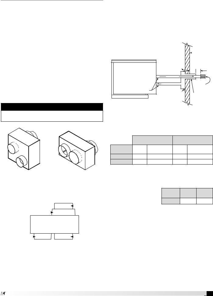
CVA-4 |
CVA-6 |
|||
4-inch Concentric |
6-inch Concentric |
|||
Venting Adapter |
Venting Adapter |
|||
|
|
Exhaust Connection |
||
Combustion Air Connection |
|
Concentric Side |
||
Concentric Side |
|
|
|
|
|
|
|
|
|
|
|
|
|
|
|
|
|
CVA |
||
|
|
|
|
|
|
|
|
|
|
|
|
Combustion Air Connection |
Exhaust Connection |
||||
Non-Concentric Side |
Non-Concentric Side |
||||
Top View
Concentric Venting – Horizontal
Refer to the diagram below for venting on horizontal concentric systems. Maintain at least 12 inches from the combustion air inlet guard to the exhaust vent terminal (Dim. B). To prevent water from running into the combustion air pipe and to allow for easy installation of the combustion air inlet guard, the combustion air pipe must terminate at least 2 inches from the exterior surface of the outside wall (Dim. A).
A = 2 inch minimum |
|
Exterior |
|
B = 12 inch minimum |
|
||
|
|
Wall |
|
|
|
|
|
|
Mounting |
|
|
|
Bracket |
|
|
|
|
A |
B |
|
EXHAUST |
|
|
Pitch vent pipe |
COMBUSTION AIR |
|
Exhaust |
|
Vent |
||
downward |
|
||
|
|
Terminal |
|
from furnace |
|
|
|
1/4 inch per foot |
Mounting |
|
|
|
Bracket |
Combustion |
|
|
|
||
|
|
Air Inlet Guard |
|
Vent Connection Diameter
Vent terminals must be used (one vent terminal included with each furnace). Construct the vent system as shown in the drawings and refer to the table for the correct vent connection diameters.
|
Non-Concentric Vent |
Concentric Vent |
||
|
Connection Diameter |
Connection Diameter |
||
Furnace Size |
Exhaust |
Combustion Air |
Exhaust |
Combustion Air |
(MBH) |
(inches) |
(inches) |
(inches) |
(inches) |
75-175 |
4 |
4 |
4 |
6 |
200-400 |
6 |
6 |
6 |
8 |
Vent Length
Refer to table for minimum and maximum vent
lengths. The total equivalent vent length must include |
||||
elbows. The equivalent |
Vent |
Minimum |
Maximum |
|
length of a 4 inch |
||||
elbow is 6 feet and the |
Length |
(feet) |
(feet) |
|
Horizontal |
5 |
70 |
||
equivalent length of a |
||||
6 inch elbow is 10 feet. |
|
|
|
|
Determine Venting Location
Determine the location of the concentric venting adapter (CVA) based on any clearances that must be maintained (follow all codes applicable).
Attach Mounting Brackets
Attach field-supplied, corrosion-resistant, mounting brackets to the CVA using corrosion-resistant sheet metal screws.
Indirect Gas-Fired Heat Modules 9
Install Exhaust Pipe
Slide the exhaust pipe through the CVA. Provide enough exhaust piping to pass through the wall (or floor) and provide the minimum clearance of 12 inches between the exhaust pipe termination and the combustion air intake. With all required clearances satisfied, attach the exhaust pipe to the CVA.
Install Combustion Air Pipe
Attach a field-supplied combustion air pipe to the concentric side of the CVA.
Be sure to provide enough combustion air piping to pass through the wall and provide the minimum clearance of 2 inches between the combustion air intake and the exterior surface of the outside wall.
Be sure to maintain the minimum clearance of
12 inches between the exhaust pipe termination and the combustion air intake.
Install CVA Assembly
Place the CVA assembly through the wall and verify that all minimum clearance requirements as specified in these instructions are met. Secure the CVA assembly to the wall with corrosion-resistant sheet metal screws through the mounting brackets.
Attach CVA Assembly to Unit
Attach the exhaust pipe to the unit’s combustion exhaust. Using an additional combustion air pipe, connect the unit’s combustion air supply intake to the combustion air connection on the CVA.
Install Combustion Air Inlet Guard and Exhaust Vent Terminal
Slide the combustion air inlet guard over the exhaust pipe and fasten it to the combustion air pipe. Attach the exhaust vent terminal to the discharge end of the exhaust piping on the outside of the building.
Seal Opening
Seal the opening between the wall and the air intake pipe using an appropriate method.
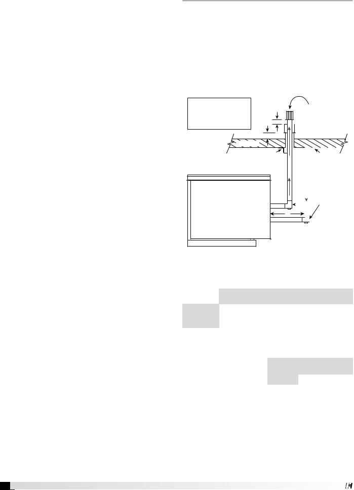
Concentric Venting – Vertical
Refer to the diagram below for venting on vertical concentric systems. Maintain at least 12 inches between the top of the combustion air inlet terminals and the bottom of the exhaust terminal. (Dim. B).
The bottom of the combustion air intake pipe must terminate above the snow line or at least 12 inches above the roof, whichever is greater.
A tee with clean-out must be provided on the combustion air and exhaust pipe to prevent debris from entering the heat exchanger.
A = 12 inch minimum, but should size according to expected snow depth
B = 12 inch minimum
B
C = 12 inch minimum
A |
|
Roof Line |
|
Mounting |
|
Bracket |
EXHAUST |
|
 C
C 
C
Exhaust Vent
Terminal

 Combustion Air
Inlet Terminal
|
|
|
|
|
|
Mounting |
|
|
|
|
|
|
|||
|
|
COMBUSTION AIR |
|
|
Bracket |
||
|
|
|
|
|
|
||
|
|
|
|
|
|
|
Tee with |
|
|
|
|
|
|
|
|
|
|
|
|
|
|
|
|
|
|
|
|
|
|
|
|
|
|
|
|
|
|
drip leg and |
|
|
|
|
|
|
|
clean-out cap |
|
|
|
|
|
|
|
||
|
|
|
|
|
|
|
|
Vent Connection Diameter
Vent terminals must be used. Construct the vent system as shown in the drawings and refer to the table for the correct vent connection diameters.
|
Non-Concentric Vent |
Concentric Vent |
||
|
Connection Diameter |
Connection Diameter |
||
|
|
|
|
|
Furnace Size |
Exhaust |
Combustion Air |
Exhaust |
Combustion Air |
(MBH) |
(inches) |
(inches) |
(inches) |
(inches) |
|
|
|
|
|
75-175 |
4 |
4 |
4 |
6 |
|
|
|
|
|
Vent Length
Refer to table. The total equivalent vent length must
include elbows. The |
|
|
|
|
equivalent length of a |
Vent |
Minimum |
Maximum |
|
4 inch elbow is 6 feet and |
Length |
(feet) |
(feet) |
|
Vertical |
10 |
70 |
||
the equivalent length of a |
||||
6 inch elbow is 10 feet. |
|
|
|
Determine Venting Location
Determine the location of the concentric venting adapter (CVA) based on any clearances that must be maintained (follow all codes referenced in these instructions).
Attach Mounting Brackets
Attach field-supplied corrosion-resistant mounting brackets to the CVA using corrosion resistant sheet metal screws.
10 Indirect Gas-Fired Heat Modules
 Loading...