


Part # 456857
Installation, Operation and Maintenance Instructions
for MAKE-UP AIR UNITS
with Direct Fired Gas Heater Option
(for natural or LP gas)
R C
ETL Listed
R
WARNING:
Improper installation, adjustment, alteration, service or maintenance can cause property damage, injury or death. Read the installation, operating, and maintenance instructions thoroughly before installing or servicing this equipment.
When suspending this unit the following ANSI standards must be followed: the standard for aircraft hangars, ANSI/NFPA 409-1985; the standard for parking structures, ANSI/NFPA 88A1985; and the standard for repair garages, ANSI/NFPA 88B-1985.
For Your Safety
If you smell gas:
1.Open windows
2.Don’t touch electrical switches
3.Extinguish any open flame
4.Immediately call your gas supplier
For Your Safety
The use and storage of gasoline or other flammable vapors and liquids in open containers in the vicinity of this appliance is hazardous.
This manual is the property of the owner, and is required for future maintenance.
Please leave it with the owner when you complete the job.
 GREENHECK
P.O. BOX 410 SCHOFIELD, WISCONSIN 54476-0410 |
January 2001 |
PH. 715-359-6171 |
|
www.greenheck.com |
|
TABLE OF CONTENTS
Gas Piping Instructions ................................................................... |
Pg. 3 |
System Startup........................................................................... |
Pgs. 4-5 |
Sequence of Operation ................................................................... |
Pg. 6 |
Trouble Shooting ....................................................................... |
Pgs. 7-8 |
Maintenance ................................................................................... |
Pg. 9 |
Canadian Requirements................................................................. |
Pg.10 |
SSOV Leak Test Procedure ............................................................ |
Pg.10 |
System Startup Documentation .................................................... |
Pg. 11 |
Gas Train Diagram ....................................................................... |
Pg. 12 |
Unit Installation
This unit should be installed according to the Greenheck IOM:
#456856 for model TSU
#457615 for model KSU
#457831 for model VSU
Warranty
Greenheck warrants this equipment to be free from defects in material and workmanship for a period of one year from the purchase date. Any units of parts which prove to be defective during the warranty period will be repaired or replaced at our option.
The motor is warranted by the motor manufacturer for a period of one year. Should the motor prove defective during this period, it should be returned to an authorized motor service station.
Greenheck will not be responsible for any installation or removal costs.
Due to continuing research, Greenheck reserves the right to change specifications without notice.
2
Gas Piping Instructions
Warnings
Leak Testing Components
All components of this or any other gas fired heating unit must be leak tested prior to placing the unit into operation. A soap and water solution should be used to perform this test. NEVER test for gas leaks with an open flame. See page 10 for safety shut off valve leak testing.
High Pressure Testing
The heater and its individual shutoff valve must be disconnected from the gas supply piping system during any pressure testing of that system at test pressures in excess of 1/2 psig (3.5 KPa).
The heater must be isolated from the gas supply system by closing its individual manual shutoff valve during any pressure testing of the gas supply piping system at test pressures equal to or less than 1/2 psig (3.5 KPa).
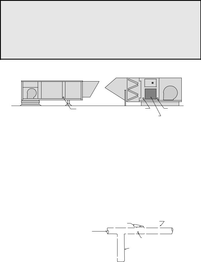
Location of Gas Connection
Housing Size 10-30 |
Housing Size 40 & 50 |
Piping Guidelines
Gas Line |
Gas Line Connection |
Gas Line Connection |
Connection |
Housing 50 |
Housing 40 |
|
Direct Gas |
|
|
Train Door |
|
All gas piping must be installed in accordance with the National Fuel Gas Code ANSI/Z223.1 - latest edition and any local codes that may apply. In Canada, the equipment shall be installed in accordance with the Installation Code for Gas Burning Appliances and Equipment, CGA B149, and Provincial Regulations for the class; which should be carefully followed in all cases. Authorities having jurisdiction should be consulted before installations are made.
The nameplate on the direct gas section door describes all the requirements about the gas being supplied to the unit. For typical operation size 10 through size 30 units need a minimum of 6 in. to a maximum of 14 in. wg for natural gas and 2 to 6 in. wg pressure for LP gas. Sizes 40 and 50 need a min. of 1/2 PSI to a max. of 5 PSI.
When the supply pressure exceeds the maximum pressure an additional regulator (furnished by others) is needed to step down the pressure. The regulators in the unit are used to adjust the maximum output temperature of the unit. Piping should be of adequate size to provide a sufficient supply of gas to meet the maximum demand with minimal pressure loss between the meter and the unit.
A manual shut off valve (gas cock) and a 1/8 in. |
|
|
|
|
|
|
|
|
|
|
|
|
|
|
|
|
|
|
|
|
|
|
|
|
|
|
|
|
|
|
|
|
|
|
|
|
|
|
|
Standard Inlet Gas Pipe Size |
|
|
|
||||||||||||
plugged tapping and a 6 in. drip leg must be installed |
|
|
|
|
|
|
|
|
|
|
|
|
|
|
|
||||||||||||
|
|
Max. |
|
<400,000 |
|
400,000 |
|
1,375,000 |
|
2,475,000 |
|
4,400,000 |
|||||||||||||||
|
|
|
|
|
|
|
|||||||||||||||||||||
prior to the gas train and must be accessible for |
|
|
|
|
|
|
|
||||||||||||||||||||
|
|
BTUs |
|
|
1,375,000 |
|
2,475,000 |
|
4,400,000 |
|
5,500,000 |
||||||||||||||||
connection to test gauge.Connections are to be made |
|
|
|
|
|
|
|
|
|
|
|
|
|
|
|
|
|
|
|
|
|
|
|
|
|
|
|
|
Pipe |
|
|
|
3/4 in. |
|
|
1in. |
|
11/2 in. |
|
2 in. |
|
21/2 in. |
|
||||||||||||
by a qualified installer and are not furnished by |
|
|
|
|
|
|
|
|
|
|
|
||||||||||||||||
|
|
Size |
|
|
|
|
|
|
|
|
|
|
|
|
|
|
|
|
|
|
|
|
|
|
|
||
Greenheck. |
|
|
|
|
|
|
|
|
|
|
|
|
|
|
|
|
|
|
|
|
|
|
|
|
|
|
|
|
|
|
|
|
|
|
|
|
|
|
|
|
|
|
|
|
|
|
|
|
|
|
|
|
|
|
|
Finally, check for leaks in the supply lines to |
|
|
|
|
|
Gas Cock |
|
Ground Joint Union |
|
|
|
|
|||||||||||||||
the unit. The factory piping has been checked |
|
|
|
|
|
|
|
|
|
|
|
|
|
|
|
|
|
|
|
|
|
||||||
From |
|
|
|
|
|
|
|
|
|
|
|
|
|
|
|
|
|
|
|
|
|
|
|
|
|||
for leaks, but should be rechecked due to |
|
Gas |
|
|
|
|
|
|
|
|
|
|
|
|
|
|
|
|
|
|
|
|
Make-Up Air Unit |
|
|||
shipping and installation. See leak test |
|
|
|
|
|
|
|
|
|
|
|
|
|
|
|
|
|
|
|
|
|
|
|
|
|
|
|
|
|
|
|
|
|
|
|
|
|
|
|
|
|
|
|
|
|
|
|
|
|
|
|
|
|
|
|
|
|
|
|
|
|
|
|
|
|
|
|
|
|
1/8 in. Plugged Tap |
|
|
|
|
|||||||||
warnings above. |
|
|
|
|
|
|
|
|
|
|
|
|
|
|
|
|
|
|
|||||||||
|
|
|
|
|
|
|
|
|
|
|
|
|
|
|
|||||||||||||
|
|
|
|
|
|
|
|
|
|
|
|
|
|
|
|
|
|
|
|
|
|
|
|
|
|
|
|
All piping should be clean and free of any |
|
|
|
|
|
|
|
|
|
|
|
|
6 in. Trap |
|
|
|
|
|
|
|
|
|
|
|
|||
foreign matter. Foreign material entering the |
|
|
|
|
|
|
|
|
|
|
|
|
|
|
|
|
|
|
|
|
|
|
|
|
|
|
|
gas train can cause problems with the valves, |
|
|
|
|
|
|
|
|
|
|
|
|
|
|
|
|
|
|
|
|
|
|
|
|
|
|
|
|
|
|
|
|
|
|
|
|
|
|
|
|
|
|
|
|
|
|
|
|
|
|
|
|
|
|
|
|
|
|
|
|
|
|
|
|
|
|
|
|
|
|
|
|
|
|
|
|
|
|
|
|
|
|
|
regulators, and the burner. |
|
|
|
|
|
|
|
|
|
|
|
|
|
|
|
|
|
|
|
|
|
|
|
|
|
|
|
3
SYSTEM STARTUP
For proper unit function and safety, follow everything in this startup procedure in the order presented. This to be done after the electrical (see base unit IOM GFC #456856) and gas connections are complete.
•Voltage meter
•Incline manometer or equivalent
Special Tools Required • Tachometer
•Thermometer
•Amperage meter
See IOM GFC #456856 (TSU) or GFC #457831(VSU) before completing these steps. 1. Check Gas Pressure
Check the gas pressure with the unit’s nameplate pressure requirements.
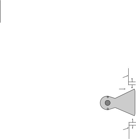
2. Burner Air Pressure Differential
Proper air velocity over the burner is critical on a direct fired gas unit. If the air velocity is not within specifications, the unit will not operate efficiently, can produce excess carbon
monoxide (CO) or other gases, and may have sporadic shutdowns. Proper air
velocity is determined by measuring the static pressure drop across the burner.
Adjustable
Top Baffle
To measure the static pressure drop, the fan should be running and be discharging 70° air. Using an incline manometer or equivalent, insert one sensor
Air Flow
into the entering air access opening (plugged test port) and the other on the downstream side, through the view port (see page 12 for locations). The proper
static pressure reading should be from .625 in. to .675 in.
Burner
If this reading is higher or lower and the air quantity (cfm) delivered to the building is acceptable, then the burner baffles will need to be adjusted (see diagram).
Open the burner access door. Using a wrench loosen the 4 screws to adjust the baffles. To increase the static pressure loss, decrease the opening size and to decrease the loss, increase the opening size. The top and bottom baffles should be of equal distance from the burner. Tighten the baffle fasteners, replace the door, turn unit on, and recheck the loss. This process may need to be repeated until the proper pressure reading is attained. This adjustment will change the air
quantity delivered by the unit and therefore should be rechecked (see start up in Base Unit IOM).
3. Pilot Pressure
The pilot pressure is preset at the factory and should not require adjustment. Pilot pressure will vary by unit size.
4. Set Maximum Discharge Temperature
Do not set the burner based on gas pressure. The burner's maximum fire rate needs to be set or the unit will over fire at startup causing unit shutdowns. To do this, the inlet air and outlet air temperatures of the unit need to be measured with the burner on high fire.
a.Determine Required Temperature Rise
Based on the geographical area, determine the winter design temperature. Subtract the winter design
temperature from the desired output temperature to get the required temperature rise. Desired output temperature - winter design temperature = temperature rise.
( Example: for Schofield, WI 70° - (-15°) = 85°F)
b.Set unit to Run at high fire.
1.On Maxitrol Series 14 systems remove and isolate the wire attached to terminal #4 of the A1014 amplifier.
2.On Maxitrol Series 44 systems remove and isolate the wire attached to terminal #3 of the A1044 amplifier.
4
 Loading...