


Document 480955
Energy Core Ventilators
®
Installation, Operation and Maintenance Manual
Please read and save these instructions. Read carefully before attempting to assemble, install, operate or maintain the product described. Protect yourself and others by observing all safety information. Failure to comply with instructions could result in personal injury and/or property damage! Retain instructions for future reference.
Model:
ECV-10
General Safety Information
Only qualified personnel should install this system. Personnel should have a clear understanding of these instructions and should be aware of general safety precautions. Improper installation can result in electric shock, possible injury due to coming in contact with moving parts, as well as other potential hazards. Other considerations may be required if high winds
or seismic activity are present. If more information is needed, contact a licensed professional engineer before moving forward.
DANGER
Always disconnect power before working on or near this equipment. Lock and tag the disconnect switch or breaker to prevent accidental power up.
CAUTION
When servicing the unit, the internal components may be hot enough to cause pain or injury. Allow time for cooling before servicing.
CAUTION
Precaution should be taken in explosive atmospheres.
1.Follow all local electrical and safety codes, as well as the National Electrical Code (NEC), the National Fire Protection Agency (NFPA), where applicable.
Follow the Canadian Electrical Code (CEC) in Canada.
2.All moving parts must be free to rotate without striking or rubbing any stationary objects.
3.Unit must be securely and adequately grounded.
4.Do not spin fan wheel faster than maximum cataloged fan RPM. Adjustments to fan speed significantly effects motor load. If the fan RPM is changed, the motor current should be checked to make sure it is not exceeding the motor nameplate amps.
5.Do not allow the power cable to kink or come in contact with oil, grease, hot surfaces or chemicals. Replace cord immediately if damaged.
6.Verify that the power source is compatible with the equipment.
7.Never open access doors to the unit while it is running.
Energy Core Ventilator 1
®

Receiving
Upon receiving the product, check to ensure all items are accounted for by referencing the delivery receipt or packing list. Inspect each crate or carton for shipping damage before accepting delivery. Alert
the carrier of any damage detected. The customer will make a notion of damage (or shortage of items) on the delivery receipt and all copies of the bill of lading which is countersigned by the delivering carrier.
If damaged, immediately contact your Greenheck Representative. Any physical damage to the unit after acceptance is not the responsibility of Greenheck Fan Corporation.
Unpacking
Verify that all required parts and the correct quantity of each item have been received. If any items are missing, report shortages to your local representative to arrange for obtaining missing parts. Sometimes it is not possible that all items for the unit be shipped together due to availability of transportation and truck space. Confirmation of shipment(s) must be limited to only items on the bill of lading.
Handling
Units are to be rigged and moved by the lifting brackets provided or by the skid when a forklift is used. Location of brackets varies by model and size. Handle each piece in such a manner as to keep from scratching or chipping the coating. Damaged finish may reduce ability of the unit to resist corrosion.
Storage
Units are protected against damage during shipment. If the unit cannot be installed and operated immediately, precautions need to be taken to prevent deterioration of the unit during storage. The user assumes responsibility of the unit and accessories while in storage. The manufacturer will not be responsible for damage during storage. These suggestions are provided solely as a convenience to the user.
Inspection and Maintenance during Storage
While in storage, inspect units once per month. Keep a record of inspection and maintenance performed
If moisture or dirt accumulations are found on parts, the source should be located and eliminated. At each inspection, rotate all moving components by hand ten to fifteen revolutions to distribute lubricant on motor and bearings. If paint deterioration begins, consideration should be given to touch-up or repainting. Units with special coatings may require special techniques for touch-up or repair.
Machined parts coated with rust preventive should be restored to good condition promptly if signs of rust occur. Immediately remove the original rust preventive coating with petroleum solvent and clean with lint-free cloths. Polish any remaining rust from surface with crocus cloth or fine emery paper and oil. Do not destroy the continuity of the surfaces. Wipe clean thoroughly with Tectyl® 506 (Ashland Inc.) or the equivalent. For hard to reach internal surfaces or for occasional use, consider using Tectyl® 511M Rust Preventive or WD-40® or the equivalent.
2Energy Core Ventilator

Table of Contents |
|
|
|
Product Overview |
||
|
|
|
|
|
|
|
Product Overview . . . . . . . . . . . |
. |
. |
3 |
The ECV brings in fresh, outdoor air and removes |
||
Standard Components . . . . . . . . . |
. |
. |
3 |
stale, exhaust air. Prior to discharging the exhaust |
||
Installation |
|
|
|
air, the energy recovery core transfers energy from |
||
Dimensional Data . . . . . . . . . . . |
. |
. |
4 |
the exhaust air to the outdoor air at an efficiency |
||
Indoor Mounting Options . . . . . . . . |
. |
. |
4 |
of 50-60%. Simply put, this unit preconditions the |
||
Outdoor Mounting Options . . . . . . . |
. |
. |
4 |
outdoor air to save money on heating and cooling |
||
Recommended Roof Openings & Weights . |
. |
. |
5 |
costs. |
||
Service Clearances . . . . . . . . . . |
. |
. |
5 |
|
|
|
Access Panel Locations . . . . . . . . |
. |
. |
6 |
|
|
|
Handling . . . . . . . . . . . . . . . |
. |
. |
6 |
Standard Components |
||
Lifting . . . . . . . . . . . . . . . . |
. |
. |
6 |
|||
Roof Curb Mounting . . . . . . . . . . |
. |
. |
7 |
|
|
|
Outdoor Air Weatherhood |
||||||
Curb Outside Dimensions and Weights . . |
. |
. |
7 |
|||
Ductwork Connections . . . . . . . . . |
. |
. |
8 |
Outdoor air weatherhood will be factory-mounted. |
||
Rail Mounting / Layout . . . . . . . . . |
. |
. |
8 |
Exhaust Weatherhood |
||
Electrical Information |
|
|
|
The exhaust weatherhood is shipped separately as a |
||
General Electrical Information . . . . . . |
. |
. |
9 |
|||
kit with its own instructions. |
||||||
Control Center Components . . . . . . . |
. |
. 10 |
||||
Dampers |
||||||
Optional Accessory Wiring Schematics . . |
. |
. 10 |
||||
Unit Overview |
|
|
|
Backdraft dampers are always included as an integral |
||
Basic Unit . . . . . . . . . . . . . . |
. |
. 11 |
part of the exhaust hood assemblies. Motorized |
|||
Optional Component Overview |
|
|
|
outdoor air and exhaust air dampers are optional and |
||
Economizer . . . . . . . . . . . . . |
. |
. 12 |
are factory-mounted and wired at the intake. |
|||
Frost Control . . . . . . . . . . . . . |
. |
. |
12 |
|
|
|
CO2 Sensor . . . . . . . . . . . . . |
. |
. 12 |
|
|
||
Dirty Filter Switch . . . . . . . . . . . |
. |
. |
12 |
|
|
|
Start-Up |
|
|
|
|
|
|
General . . . . . . . . . . . . . . . |
. |
. |
13 |
|
|
|
Pre Start-Up Checklist . . . . . . . . . |
. |
. 13 |
|
|
||
Special Tools Required . . . . . . . . . |
. |
. 13 |
|
|
||
Start-Up Checklist . . . . . . . . . . . |
. |
. 13 |
|
|
||
Optional Accessories Checklist . . . . . |
. |
. 14 |
|
|
||
Start-Up Components |
|
|
|
|
|
|
Fans . . . . . . . . . . . . . . . . |
. |
. |
15 |
|
|
|
EC Motors . . . . . . . . . . . . . . |
. |
. |
15 |
|
|
|
Optional Start-Up Components |
|
|
|
|
|
|
Dirty Filter Switch . . . . . . . . . . . |
. |
. |
15 |
|
|
|
Economizer . . . . . . . . . . . . . |
. |
. 16 |
|
|
||
Frost Control . . . . . . . . . . . . . |
. |
. |
16 |
|
|
|
Routine Maintenance . . . . . . . . . |
. 17-18 |
|
|
|||
Troubleshooting |
|
|
|
|
|
|
Economizer Alarms . . . . . . . . . . |
. |
. 19 |
|
|
||
Airflow. . . . . . . . . . . . . . . . |
. |
. 20 |
|
|
||
Unit . . . . . . . . . . . . . . . . . |
.21-22 |
|
|
|||
Maintenance Log . . . . . . . . . . . |
. |
. |
23 |
|
|
|
Our Commitment . . . . . . . . . Backcover
Energy Core Ventilator 3

Installation
Dimensional Data
Unit Size |
|
Exterior Dimensions |
|
|
|
Unit Opening Dimensions |
|
|||||||
|
|
|
|
|
|
|
|
|
|
|
|
|
|
|
|
|
A |
B |
C |
D |
|
E |
F |
G |
|||||
|
|
|
|
|||||||||||
|
|
|
|
|
|
|
|
|
|
|
|
|
|
|
ECV-10 |
|
54.8 |
28.9 |
43.9 |
|
18.4 x 15.9 |
|
13.6 x 13.6 |
8.2 x 11.3 |
16.5 x 11.5 |
||||
|
|
|
|
|
|
|
|
|
|
|
|
|
|
|
All dimensions are in inches. |
|
|
|
|
|
|
|
|
|
|||||
|
|
|
|
|
|
|
|
|
|
|
|
|
||
Unit Size |
|
|
Intake and Discharge Options |
|
|
|
|
|
||||||
|
Bottom |
|
Top |
|
Side |
|
End |
|
|
|
||||
|
|
|
|
|
|
|
|
|
||||||
|
|
|
|
|
|
|
|
|
|
|
|
|
|
|
OA Intake |
|
|
|
|
X |
|
|
|
|
X |
|
|
|
|
|
|
|
|
|
|
|
|
|
|
|
|
|
|
|
SA Discharge |
|
|
X |
|
|
|
|
|
|
X |
|
|
|
|
|
|
|
|
|
|
|
|
|
|
|
|
|
|
|
RA Intake |
|
|
X |
|
|
|
|
|
|
X |
|
|
|
|
|
|
|
|
|
|
|
|
|
|
|
|
|
|
|
EA Discharge |
|
|
|
|
X |
|
|
|
|
X |
|
|
|
|
|
|
|
|
|
|
|
|
|
|
|
|
|
|
|
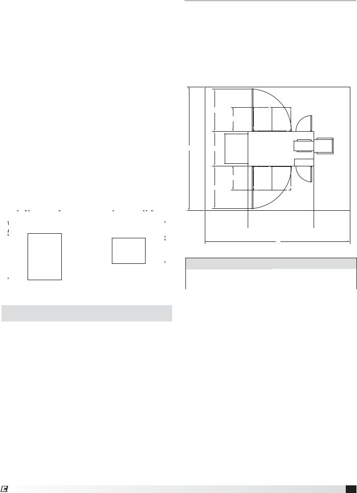
Indoor Mounting Options
|
E |
|
|
|
|
|
|
|
OUTDOOR AIR INTAKE |
EXHAUST AIR |
E |
|
|
|
DISCHARGE |
|
|
|
|
|
|
|
|
|
|
|
|
D |
C |
SUPPLY AIR |
|
|
|
|
DISCHARGE |
|
|
|
|
|
|
|
D |
|
|
(NON |
A |
|
RETURN AIR INTAKE |
|
|
|
||
|
|
ELECTRICAL |
B |
|
|
|
|
SIDE) |
|
EXHAUST AIR
DISCHARGE
E
SUPPLY AIR
DISCHARGE
|
F |
(NON |
A |
|
ELECTRICAL |
OUTDOOR AIR INTAKE
D
C
G
RETURN AIR INTAKE
B
SIDE)
End Connections |
Top and Bottom Connections |
Outdoor Mounting Options
EXHAUST AIR
DISCHARGE
SUPPLY AIR
DISCHARGE
(NON
F
A ELECTRICAL
SIDE)
EXHAUST AIR
DISCHARGE
E
C
SUPPLY AIR
DISCHARGE
G
|
OUTDOOR AIR |
(NON |
|
INTAKE |
|
B |
RETURN AIR INTAKE |
|
|
|
ELECTRICAL
SIDE)
C
G
OUTDOOR AIR INTAKE
B |
RETURN AIR INTAKE |
Outdoor Air Discharge Bottom |
Outdoor Air Discharge End |
4Energy Core Ventilator
Recommended Roof Openings & Weights
Position the unit roof opening such that the supply discharge and return inlet of the unit will line up with the corresponding ductwork. Be sure to allow for the recommended service clearances when positioning opening (see Service Clearances). Do not face the outdoor air intake of the unit into prevailing wind and keep the intake away from any other exhaust fans. Likewise, position the exhaust discharge opening away from outdoor air intakes of any other equipment.
When cutting only duct openings, cut opening 1-inch (25 mm) larger than duct size to allow clearance for installation. Area enclosed by roof curb must comply with clearance to combustible materials. If the roof is constructed of combustible materials, area within the roof curb must be ventilated, left open, or covered with non-combustible material which has an “R” value of at least 5. If area within curb is open, higher radiated sound levels may result.
Where the supply or warm air duct passes thru a combustible roof, a clearance of 1-inch must be maintained between the outside edges of the duct and combustible material in accordance with NFPA Standard 90A.
4.4 |
|
|
|
|
|
13.5 |
|
|
|
|
|
|
13.3 |
|
|
|
|
|
|
|
3.4 |
|
|
|
|
|
|
|
|
|
|
|
|
|
|
|
|
||||||||||||
|
|
|
|
|
|
|
|
|
|
|
|
|
|
|
|
|
|
|
|
|
|
|
|
|
5.2 |
|
|
|
|
|
|
|
|
|
|
|
|
|
|
|
|
|
|
|
|
|
|
|
|
|
|
|
|
|
|
|
|
|
|
|
|
|
|
|
|
|
|
|
|
|
|
|
||
|
|
|
|
|
|
|
|
|
|
|
|
|
|
|
|
|
|
|
7.0 |
|||||
|
|
|
|
|
|
|
|
|
|
|
|
|
|
|
|
|
|
|
|
|
||||
|
|
|
|
|
|
|
|
|
|
|
|
|
|
|
|
|
|
|
|
|
|
|
|
|
|
|
|
|
|
|
|
|
|
|
|
|
|
|
|
|
|
|
|
|
|
|
|
|
|
|
|
|
|
|
|
|
|
|
|
|
|
|
SUPPLY AIR |
|
|
|
|
|
|
|||||
|
|
|
|
|
|
|
|
|
|
|
|
|
|
10.2 |
||||||||||
|
|
|
|
|
|
RETURN |
|
|
|
|
DISCHARGE |
|
|
|
|
|
||||||||
18.5 |
|
|
|
|
|
|
|
|
|
|
|
|
||||||||||||
|
|
|
|
AIR INTAKE |
|
|
|
|
|
|
|
|
|
|
|
|
|
|
|
|
||||
|
|
|
|
|
|
|
|
|
|
|
|
|
|
|
|
|
|
|
|
|
|
|
|
|
|
|
|
|
|
|
|
|
|
|
|
|
|
|
|
|
|
|
|
|
|
|
|
|
|
|
|
|
|
|
|
|
|
|
|
|
|
|
|
|
|
|
|
|
|
|
|
|
|
|
|
|
|
|
|
|
|
|
|
|
|
|
CONTROL PANEL |
|
|
|
|
|
|||||||
|
|
|
|
|
|
|
|
|
|
|
|
|
|
|
|
|
|
|
|
|
|
|
|
|
|
|
|
|
|
|
|
|
|
|
|
|
|
|
|
|
|
|
|
|
|
|
|
|
|
Unit Size |
Approx. Weight (lbs.) |
|
|
ECV-10 |
485 |
|
|
All dimensions are in inches. *Weight assumes outdoor unit with filters, weatherhoods, outdoor air intake damper, controls and internal double-wall sheet metal.
Service Clearances
The ECV-10 unit requires minimum clearances to perform routine maintenance, such as filter
replacement and energy core inspection. Blower and motor assemblies, energy recovery core and filter sections are always provided with a service door
or panel for proper component access. Clearances for component removal may be greater than the service clearances, refer to drawing below for these dimensions.
C
ECORE
A D
CONTROL
PANEL
ECORE
C
 F
F
 G
G
 H
H
B
Recommended Service Clearances
Unit Size |
A |
B |
C |
D |
E |
F |
G |
H |
|
|
|
|
|
|
|
|
|
ECV-10 |
102.9 |
120.8 |
35.5 |
28.9 |
22 |
36 |
54.8 |
30 |
|
|
|
|
|
|
|
|
|
All dimensions are in inches.
Energy Core Ventilator 5
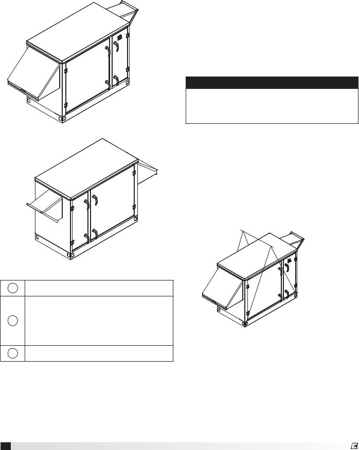
Access Panel Locations
The ECV is provided with access panels on both sides of the unit. The nonelectrical side can be placed against a wall. Clearance to the electrical side is essential to provide access to the control center and component maintenance.
1
2
Electrical Side
2
3
Handling
While this unit was constructed with quality and dependability in mind, damage still may occur during handling of the unit for installation.
The system design and installation should follow accepted industry practice, such as described in the ASHRAE Handbook. Adequate space should be left around the unit for filter replacement and
maintenance. Sufficient space should be provided on the side of the unit for routine service and component removal should that become necessary.
Lifting
WARNING
All factory provided lifting lugs must be used when lifting the unit. Failure to comply with this safety precaution could result in property damage, serious injury or death.
1.Before lifting, be sure that all shipping material has been removed from unit.
2.To assist in determining rigging requirements, weights are shown under the Recommended Roof Openings & Weights section.
3.Unit must be lifted by all lifting lugs provided on base structure.
4.Rigger to use suitable mating hardware to attach to unit lifting lugs.
5.Spreader bar(s) must span the unit to prevent damage to the cabinet by the lift cables.
Nonelectrical Side
1Control Center Core
Filters
2Inlet Dampers Bypass Damper Blowers
3Blowers
6Energy Core Ventilator
6.Always test-lift the unit to check for proper balance and rigging before hoisting to desired location.
7.Never lift units by weatherhoods.
8.Never lift units in windy conditions.
9.Preparation of curb and roof openings should be completed prior to lifting unit to the roof.
10.Check to be sure that gasketing (supplied by others) has been applied to the curb prior to lifting the unit and setting on curb.
11.Do not use fork lifts for handling unit.
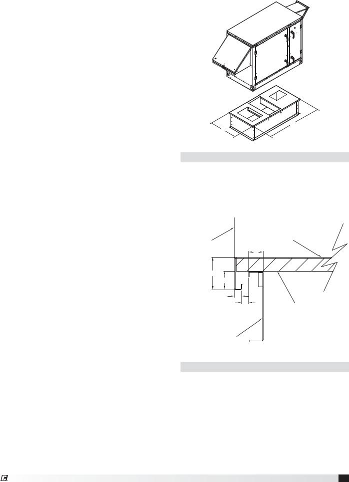
Roof Curb Mounting
Rooftop units require curbs to be mounted first. The duct connections must be located so they will be clear of structural members of the building.
1.Factory Supplied Roof Curbs: Roof curbs are Model GKD. The GKD ships in a knockdown kit (includes duct adapter) and requires field
assembly (by others). Assembly instructions are included.
2.Install Curb: Locate curb over roof opening and fasten in place. (Refer to Recommended Roof Openings). Check that the diagonal dimensions are within ±1/8 inch of each other and adjust
as necessary. For proper unit operation, it is important that the installation be level. Shim as required to level.
3.Install Ductwork: Installation of all ducts should be done in accordance with SMACNA and AMCA guidelines. Duct adapter provided to support ducts prior to setting the unit.
4.Set the Unit: Lift unit to a point directly above the curb and duct openings. Guide unit while lowering to align with duct openings. Roof curbs fit inside the unit base. Make sure the unit is properly seated on the curb and is level.
Curb Outside Dimensions and Weights
A
B
Unit Size |
A |
B |
Curb Weight (lbs.) |
|
|
|
|
ECV-10 |
52.2 |
26.3 |
60 |
|
|
|
|
All dimensions are in inches. Weight is for 14-inch high model GKD curbs.
Side of Unit |
Base |
|
|
|
A |
B |
|
C |
|
D |
|
E |
1-inch Insulation |
|
Roof Curb
Curb Cap Details for Factory Supplied Roof Curbs
Unit Size |
A |
B |
C |
D |
E |
|
|
|
|
|
|
ECV-10 |
1.9 |
5.3 |
4.3 |
4.3 |
0.8 |
|
|
|
|
|
|
All dimensions are in inches.
Energy Core Ventilator 7
Ductwork Connections
Examples of poor and good fan-to-duct connections are shown. Airflow out of the fan should
be directed straight or curve |
|
|
|
|
||||
same direction as the |
|
|
|
|
|
|||
fan wheel rotates. Poor |
|
|
|
tion |
||||
|
|
|
|
|
|
|
a |
|
duct installation will |
|
|
t |
|
||||
|
R |
o |
|
|
||||
|
|
|
|
|||||
|
|
|
|
|
||||
result in low airflow and |
|
|
|
|
||||
other system effects. |
|
|
|
|
POOR |
|||
|
|
|
|
|
|
|
|
|
|
|
|
tion |
Length of Straight Duct |
||||
|
|
a |
||||||
|
t |
|
||||||
R |
o |
|
|
|
|
|
|
|
|
|
|
|
|
|
|
|
|
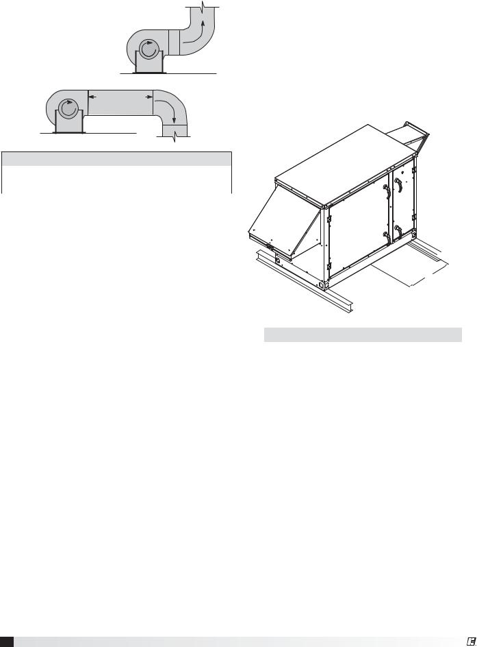
Rail Mounting / Layout
•Rails designed to handle the weight of the unit should be positioned as shown on the diagram (rails by others).
•Make sure that rail positioning does not interfere with the supply air discharge opening or the exhaust air intake opening on the unit. Avoid area dimensioned “B” below.
•Rails should extend beyond the unit a minimum of 12 inches on each side.
•Set unit on rails.
GOOD
Recommended Discharge Duct Size and Length
Model |
Blower Size |
Duct Size |
Straight Duct Length |
|
|
|
|
ECV-10 |
10-6 |
14 x 14 |
36 ft. |
|
|
|
|
All dimensions shown in inches.
•Recommended duct sizes are based on velocities across the cfm range of each model at approximately 800 feet per minute (FPM) at minimum airflow and up to 1600 fpm at maximum airflow. Recommended duct sizes are only intended to be a guide and may not satisfy the requirements of the project. Refer to plans for appropriate job specific duct size and/or velocity limitations.
•Straight duct lengths were calculated based on 100% effective duct length requirements as prescribed in AMCA Publication 201. Calculated values have been rounded up to nearest foot.


 A
A
B
Unit Size |
A |
B |
|
|
|
ECV-10 |
4.2 |
11.5 |
|
|
|
All dimensions are in inches.
8Energy Core Ventilator
 Loading...