


SERIES 14 INSTALLATION INSTRUCTIONS and field service check list
|
A1014L1 Amplifier / |
AD1214 Amplifier |
Mixing Tube and Sensor |
|
|
||
A1014 Amplifier |
AD1014/AD1014L1 |
|
|
|
Amplifier-Selectors |
|
|
|
Table of Contents |
Page 2 |
Introduction and Dimensions |
Page 3 |
Specifications |
|
Installation of Components |
Page 4 & 5 Field Service Checklist |
|
Page 6 |
Preliminary Circuit Analysis |
|
Low Fire Start Time Adjustment |
|
Sensitivity Adjustment |
Page 7 |
Wiring Diagrams |
Page 8 |
Temperature Calibration |
|
Valve Adjustments |
|
|
Remote Temperature Selector
Override Stat
Valves
System Components |
||
Amplifiers: |
TS114G (90° to 140° F) |
|
A1014 (use with all temperature ranges) |
TS114J (110° to 160° F) To be used w/ AD1014-1116 |
|
A1014L1 (all ranges - adjustable low fire start duration) |
TS214__ (dual sensor - any combination of 2 standard ranges available) |
|
Amplifier-Selectors: (with integral temperature dial) |
Example - TS214G (55° to 90° F and 90° to 140° F, use w/TD114 & TD114G, |
|
AD1014-4080 (40° to 80° F) |
or TD214G [selector w/switch], or AD1214G) |
|
AD1014-5590 (55° to 90° F) |
Example - TS214AD (80° to 130° F and 200° to 250° F, use w/TD114A & |
|
AD1014-1116 (110° to 160° F) |
TD114D, or TD214AD [selector w/ switch], or AD1214AD) |
|
AD1014-1621 (160° to 210 ° F) |
Mixing Tubes: use with Sensors |
|
AD1014L1-4080 (40° to 80° F - adjustable low fire start duration) |
MT1-9 or 2-9 (9" length) |
|
AD1014L1-5590 (55° to 90° F - adjustable low fire start duration) |
MT1-12 or 2-12 (12" length) |
|
AD1014L1-1116 (110° to 160° F - adjustable low fire start duration) |
MT1-23 or 2-23 (23" length) |
|
AD1014L1-1621 (160° to 210° F - adjustable low fire start duration) |
MT1-28 or 2-28 (28" length) |
|
MT1-57 (57" length) |
||
Dual Temperature Amplifier-Selectors: |
||
Valves: |
||
AD1214__ (integral dual selector - any comb. of 2 standard ranges avail.) |
||
M411 (3/8" & 1/2" pipe size) |
||
Example - AD1214BC (120° to 170° F and 160° to 210° F, use w/TS214BC |
||
M511 (1/2" & 3/4" pipe size) |
||
Example - AD1214AD (80° to 130° F and 200° to 250° F, use w/TS214AD |
||
M611 (3/4" & 1" pipe size) |
||
Remote Temperature Selectors: |
||
TD114 (55° to 90° F w/override 0° to 40° over set point) |
MR212D (1", 1-1/4", 1-1/2" pipe size) |
|
MR212E (1-1/2" & 2" pipe size) |
||
TD114A (80° to 130° F) |
||
MR212G (2-1/2" & 3" pipe size) |
||
TD114A-1 (80° to 130° F w/ override 0° to 40° F over set point) |
||
MR212J (4" flanged) |
||
TD114B (120 to 170° F) |
||
MR212-2D, E, G, J (same as above except used for 2-speed blower or dual fuel |
||
TD114C (160° to 210° F) |
||
operation) |
||
TD114D (200° to 250° F) |
||
NOTE: M (Modulator) valve requires a pressure regulator for high fire setting. MR |
||
TD114E (100° to 250° F) |
||
TD114F (40° to 80° F w/override 0° to 40° over set point) |
(Modulator-Regulator) valve requires no pressure regulator up to 5 psi. |
|
TD114G (90° to 140° F) |
Optional: |
|
TD114-1 (55° to 90° F w/120° to 170° F override) * use w/TS114 |
||
Dual Temperature Selector: |
||
TD114-2 (55° to 90° F w/two outputs) |
||
DOOR HEATERS - |
||
TD114G-2 (90° to 140° F w/two outputs) |
||
TD114HD use w/TS114 (door closed 55° to 90° F/open 90° to 140° F) |
||
NOTE: Remote Selector and Discharge Temperature Sensor must have same |
||
PAINT SPRAY BOOTHS OR OTHER DUAL APPLICATIONS- |
||
temperature range to be compatible. |
||
TD214__ (dual selector w/switch - any comb. of 2 standard ranges avail.) |
||
Optional: ETD-1 enclosure, EFP-1 cover plate only - no enclosure |
||
Example - TD214G (55° to 90° F [spray] and 90° to 140° F [dry], use w/TS214G |
||
Discharge Air Temperature Sensors: use with Mixing Tube |
||
Example - TD214AD (80° to 130° F and 200° to 250° F, use w/TS214AD |
||
TS114 (55° to 90° F) |
||
TD214__X (same as TD214__, less enclosure) |
||
TS114A (80° to 130° F) |
||
Inlet Air Temperature Sensors: use with Mixing Tube |
||
TS114B (120° to 170° F) |
||
TS10765A (8:1 ratio) |
||
TS114C (160° to 210° F) |
||
TS10765B (5:1 ratio) |
||
TS114D (200° to 250° F) |
||
TS10765C (3.5:1 ratio) |
||
TS114E (100° to 250° F) |
||
Override Stat: (use only with TD114, F ,-1, A-1) |
||
TS114F (40° to 80° F) |
||
T115 (40° to 90° F) |
||
|
||
|
|
|
©2007 Maxitrol Company, All Rights Reserved |
1 |
|

Introduction and Dimensions
Selectra SERIES 14 electronic gas flame modulation systems are designed primarily for make-up air heating, as components of direct fired equipment. They may be field installed on existing equipment or specified for new equipment installation. Natural, manufactured, mixed, LP and LP gas air mixture are compatible gases.
The systems utilize Modulator or Modulator-Regulator valves. Amplifiers are available with adjustable low-fire start duration, and with integral or remote temperature selection. A discharge air temperature sensor is mounted within a mixing tube housing.
Optional - a room override thermostat provides space temperature control by raising the discharge air temperature to a pre-selected point - when used in conjunction with the remote temperature selector.
Optional - an inlet air sensor (and mixing tube) provides inverse change in discharge air for each degree change in inlet air - when installed in a convenient duct location upstream of the burner.
Optional - a dual temperature selector replaces TD114 to provide dual control for door heaters, or other applications such as paint spray booths (TD214_ or _X, or AD1214_).
TD114
MOUNTING
HOLES
A1014L1,
AD1014,
AD1014L1
(AD models have integrated temperature dial in lower right corner, logo label in upper left corner)
A1014
ETD-1
AD1214
(SEE PAGE 1)
MIXING TUBES
©2007 Maxitrol Company, All Rights Reserved |
2 |
Specifications
Power Requirements: 24 VAC, 50/60 Hz Class II transformer
NOTE: Transformer secondary must not be grounded in any portion of the circuit external to a Maxitrol amplifier. If existing transformer is grounded, a separate isolated transformer must be used. Electrical interference may effect performance and/or damage equipment.
Ambient Limits:
Operating.....-40o to 125o F / -40o to 52o C Non-operating.....-50o to 185o F / -46o to 85o C
Gases: Suitable for application in natural, manufactured, mixed gases, liquefied petroleum gases and LP Gas Air Mixture piping systems.
Vent: M411, 511, 611.....vertical vent outlet 1/8" NPT - 12A06 installed
MR212.....two vents located in upper housing, both equipped
with vent limiting means |
|
|
Pressure Limits: |
|
|
Maximum Discharge Pressure (M411, 511, 611)..... |
7" w.c. / |
|
17 mbar |
|
|
Static Pressure Rating (M411, 511, 611)................. |
5.0 psi / |
|
345 mbar |
|
|
Maximum Operating Inlet Pressure |
|
|
M411, 511, 611..... |
1 psi / 70 mbar |
|
MR212.....5.0 psi / 345 mbar |
|
|
Maximum Emergency Exposure* |
|
|
M411, 511, 611..... |
3.0 psi / 210 mbar |
|
MR212.....12.5 psi / 862 mbar
* May not function properly at this pressure, but will suffer no internal damage
Installation of Components
Control wires connected to the Override Stat, Discharge Air Sensor, or Remote Temperature Selector must not be run close to or inside conduit with power or ignition wires. Doing so may cause the unit to function erratically or may destroy the amplifier. If shielded wires are used, shield must be insulated and grounded at the amplifier location only.
Wiring Run: If control wiring is inside conduit with line voltage wiring, use shielded cable up to 100 ft. For best results up to 200 ft., run control wiring in separate conduit. For longer runs see Remote Selector below.
Amplifier / Amplifier-Selector: contains the wiring terminals and sensitivity adjustment - install in any convenient location that is protected from the weather and contaminated atmosphere.
Remote (or Dual) Selector: Install in control cabinet or other chosen location. NOTE: Suffix letters must match, e.g. TS114A must be used with TD114A. For wiring runs longer than 200 ft. substitute ES261-1/ES261-2 for TD114. The ES261s are a 2-piece version of the TD114. ES261-1 is a temperature setting dial only, ES261-2 must be mounted at furnace location.
Discharge Temperature Sensor / Mixing Tube Assembly: sensor housed in mixing tube, install in discharge air stream.
Optional:
Dual Temperature Selector: see preceding Remote/Dual selector.
Room Override Stat: mount in heated area not in direct path of discharge air stream.
Inlet Air Sensor: install in convenient location upstream of burner, in intake air duct.
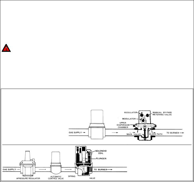
Typical Gas Trains
Modulator (M) or Modulator-Regulator (MR) Valve: Mount in upright position in horizontal run of pipe, downstream of other controls - a separate gas pressure regulator must be used with any modulator (M) valve.
MR Valve: Modulator-regulator valve
M Valve: Regulator upstream of modulator valve
|
|
|
|
|
|
|
|
|
|
|
|
|
|
|
|
|
|
|
|
©2007 Maxitrol Company, All Rights Reserved |
3 |
|||
 Loading...