


Centrifugal Inline Fans
Models SQ and BSQ
Direct and Belt Drive
April |
2008 |
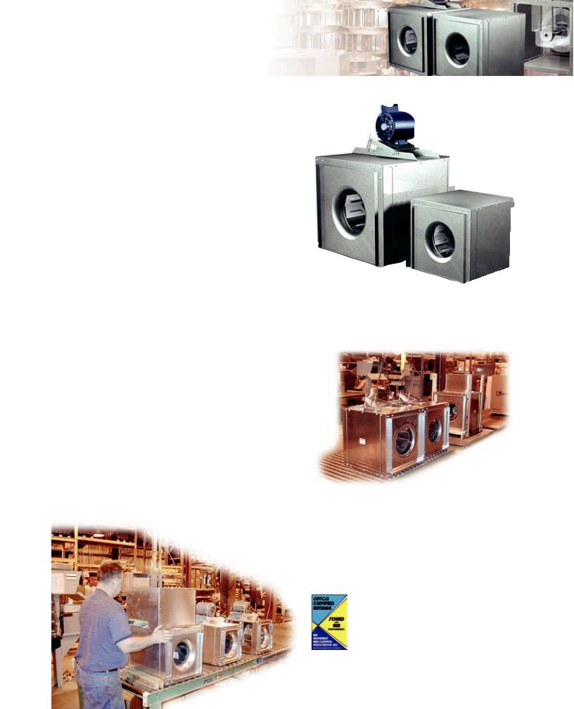
Models SQ & BSQ
Centrifugal Square Inline Duct Fans
Greenheck’s model SQ and BSQ centrifugal inline fans feature a unique combination of installation flexibility, rugged construction, ease of service, high efficiency, and
low sound levels. These compact inline fans are the ideal indoor clean air applications including intake, exhaust, return, up air systems where space is a prime consideration. The costly square to round transition pieces are eliminated reducing installation costs. The square housing design, compact size, and straight-thru airflow also give the
system designer the flexibility to mount SQ and BSQ fans in any configuration - horizontal, vertical, or at any angle.
•Broadest performance in the industry, up to 4 in. wg
(1,000 Pa) and 28,000 cfm (47,000 m3/hr).
•Performance as cataloged is assured. All fan sizes are tested in our AMCA Accredited Laboratory, and all models are licensed to bear the AMCA sound and air performance seals.
•UL Listed for electrical
•Greenheck subjects these products to extensive life testing, assuring you the fans will provide many years of reliable performance
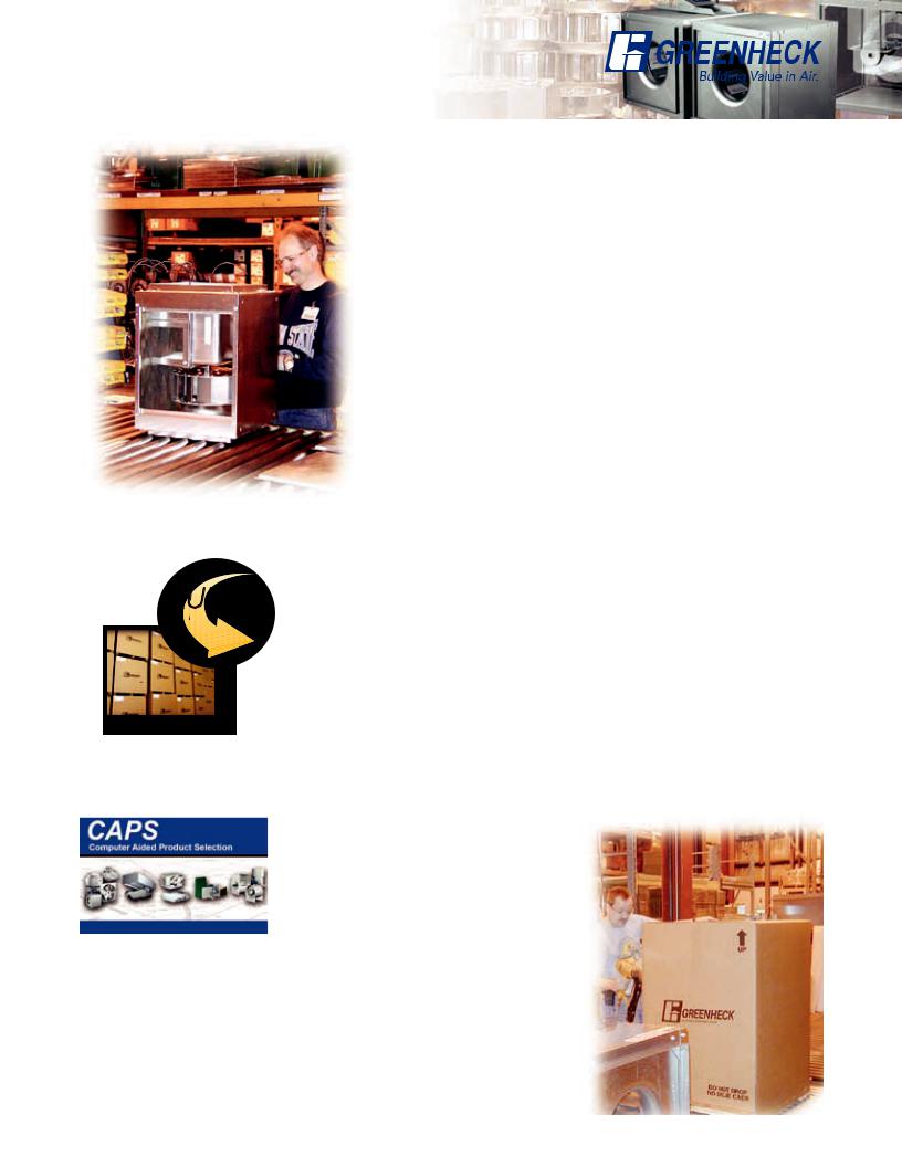
World Class Manufacturing
Greenheck’s skilled production workers use cost-effective machines and unique dies, designed and built by our own engineers to add innovative features and greater strength to our centrifugal inline fans. Our advanced manufacturing processes and quality control procedures always ensure the highest product quality. And just to be sure you get the peace-of-mind you expect when you specify Greenheck, our assembly inspectors test run and monitor every fan before it leaves the factory. Results of these tests are kept in permanent records for future reference.
*UL is optional and must be specified. SQ and BSQ models are listed for electrical (UL/cUL 705) File no. E40001
Greenheck Fan Corporation certifies the model SQ and BSQ fans shown herein are licensed to bear the AMCA Seal. The ratings shown are based on tests and procedures performed in accordance with AMCA Publication 211 and Publication 311 and comply with the requirements of the AMCA Certified Ratings Program. The certified ratings for models SQ and BSQ are shown on pages 11 to 41.
2
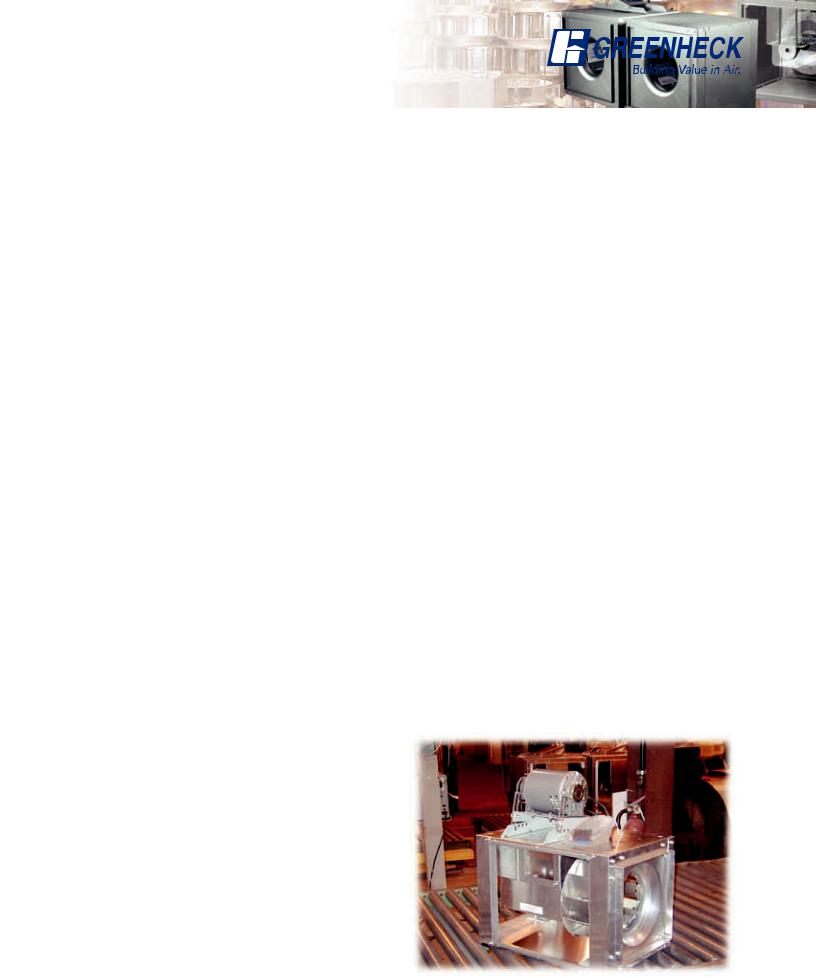
The Greenheck Standard
Over the past 40 years we have listened to your needs and input to remain the industry leader.
•Each fan is tested at the factory prior to shipping. The test includes vibration check, adjusting RPM, and maximum amp draw test.
•Each fan displays a permanently stamped metal nameplate with complete model number, mark, and unique serial number for future identification.
•Packages are tested in accordance with ISTA (International Safe Transit Association) standards and procedures.
Turn to our inline fans to meet your requirements for applications in office buildings, schools, and hospitals to name a few.
Quick Delivery and Quick Build Programs
More than 40 model SQ and BSQ fans are stocked in four unique configurations within our strategically located Greenheck warehouses.
Greenheck’s Quick Delivery (QD) Program includes hundreds of in-stock ventilation products and accessories, available for shipment to your job
site in less than 24 hours.
Our Quick Build (QB) Program ensures rapid response time with your needs dictating manufacturing time. Your custom product configuration can be manufactured in one, three, five, or ten days and then shipped to your job site.
Leading Edge Technical Support
When you need extensive product or installation and operating manual (IOM) information, our products are supported by the industry’s best product literature, electronic media, and computer aided product selection (CAPS) program. You’ll also find this information on our website at www.greenheck.com
You can always count on personal service and expertise from our national and international representative organization. To locate your nearest Greenheck representative, call 715 359 6171 or visit our website at www.greenheck.com
3
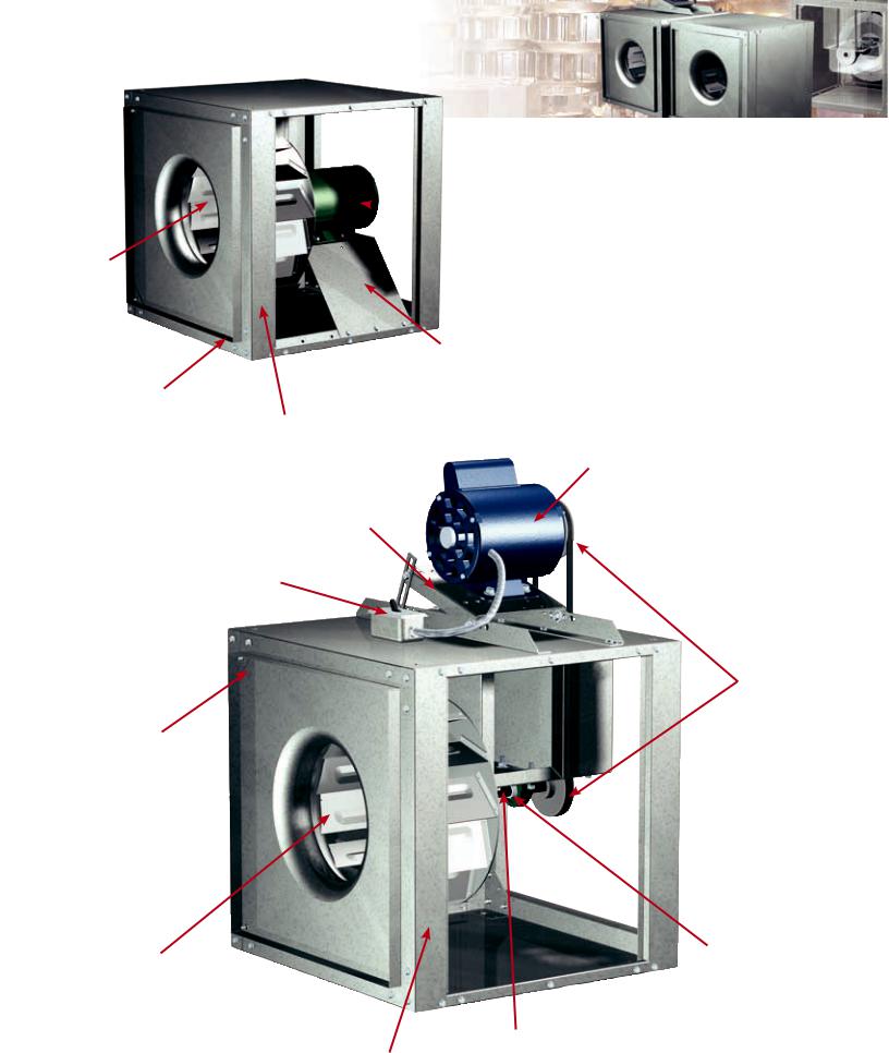
 MOTOR
MOTOR
WHEEL
DRIVE FRAME
DUCT COLLARS
CABINET
CONSTRUCTION
MOTOR
DRIVE FRAME
DISCONNECT
SWITCH
DUCT COLLARS
WHEEL
FAN SHAFT
CABINET
CONSTRUCTION
DRIVE
ASSEMBLY
BEARINGS
4
Standard Construction Features
Cabinet Construction
The fan housing is constructed of rigid structural members and formed galvanized steel panels.
(Aluminum construction is optional in all SQ sizes 60 160 and in BSQ sizes 70 300.)
Wheel
An aluminum, backward inclined, non-overloading centrifugal wheel is utilized to deliver maximum efficiency. Each wheel is statically and dynamically balanced.
Duct Collars
Inlet and discharge duct collars are provided for easy duct connection. The square design provides a larger discharge area than tubular, centrifugal, and vane axial fans; outlet velocities are reduced for quieter operation.
Access Panels
The cabinet construction features two side access panels. Access panels permit easy access to all internal components. The access panels have been removed on the drawing.
Drive Frame
Constructed from heavy gauge steel. Belt adjustment is accomplished by loosening fasteners, sliding the motor plate, and retightening fasteners.
Motor
Permanently lubricated, sealed ball bearing motors are selected to provide years of troublefree operation with minimal maintenance.
BEARINGS
100 percent factory tested and designed specifically for air handling applications with a minimum L10 life in excess of 100,000 hours (L50 average life of 500,000 hours).
Drive Assembly
Drives are sized for a minimum of 150 percent of driven horsepower. Machined cast iron pulleys are factory set to the required RPM and adjustable for final system balancing. Belts are static free and oil resistant.
Fan Shaft
Precisely sized, ground, and polished so the first critical speed is at least 25 percent over the maximum opportunity speed. Close tolerances where the shaft makes contact with bearings result in longer bearing life.
Disconnect Switch
NEMA-1 disconnect switch is factory mounted and wiring is provided from the motor as standard. All wiring and electrical components comply with the National Electric Codes and materials are UL Listed. Other NEMA enclosure disconnect switches are optional.
5
Options and Accessories
ALUMINUM CONSTRUCTION
Aluminum construction is available for all direct drive sizes 60-160 and belt drive sizes 70-300.
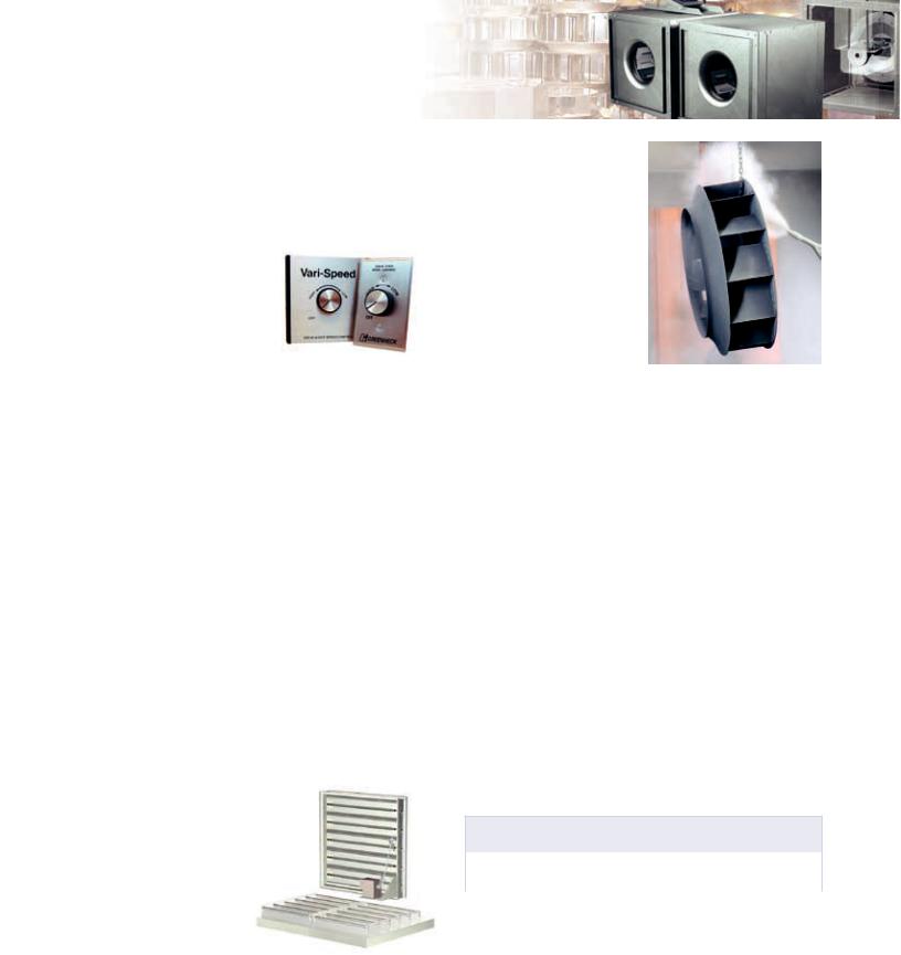
Speed Controllers
Available for use with shaded pole and permanent split capacitor (PSC)
open motors on model SQ fans. They provide an economical means of system balancing with direct drive fans.
INLET and DISCHARGE GUARDS
Inlet and discharge guards provide protection for non-ducted applications. Guards are fabricated of welded wire on a galvanized steel frame. They are easily removed for maintenance and inspection.
MOTOR COVER and BELT GUARD
For belt driven fans, combination motor cover and belt guards constructed of galvanized steel are available for protection of motors, drives, and personnel. Standard on units specified with UL.
DIRECT DRIVE MOTOR COVER
Formed, galvanized steel motor covers are available to isolate direct drive motors from the airstream. When motor covers are furnished, vents to the exterior of the fan are provided to ensure sufficient motor cooling.
GRAVITY DAMPERS
Gravity or motorized parallel blade dampers (model WD-330) are available
for duct mounting. These dampers feature sturdy galvanized frames with prepunched mounting holes, aluminum blades with felt edges, and a balanced design for minimal resistance to airflow.
CONTROL DAMPERS
Square, opposed blade volume control dampers
(model VCD) are available for duct mounting. These dampers feature sturdy galvanized frames with prepunched mounting holes, steel blades with vinyl seals, and flexible metal jamb seals. A balanced design results in minimal resistance to airflow.
Coatings
Wide variety of coatings and colors are available.
Decorative coatings are available in sixteen standard colors.
Protective coatings are available in a choice of five electrostatic applied powders providing an available selection for most environments.
All Greenheck coatings and resistance charts can be found in the performance coatings catalog.
INLET VANE
Variable inlet vane dampers (model IVDE) are available for models SQ and BSQ sizes 140-420 and are factory assembled to the fan. They can be specified for either manual or automatic operation with controls furnished by others. These dampers are constructed of heavy gauge painted steel
and feature uniform blade movement for positive control. Companion inlet rings for round duct connections are also available.
Insulated Housing
For noise reduction and condensation control, the interior of the fan housing can be lined with a fiberglass duct liner (1/2 and 1 in. being standard).
The optional motor cover can also be insulated.
The table depicts the dB reduction that can be obtained in each octave band for the insulated housing and motor cover together.
Approximate dB Sound Attenuation
Octave Band |
1 |
2 |
3 |
4 |
5 |
6 |
7 |
8 |
|
|
|
|
|
|
|
|
|
Sizes 60 - 130 |
-2 |
-7 |
-4 |
-4 |
-6 |
-13 |
-13 |
-9 |
|
|
|
|
|
|
|
|
|
Sizes 140 - 420 |
-3 |
-2 |
-5 |
-4 |
-5 |
-5 |
-7 |
-8 |
|
|
|
|
|
|
|
|
|
WIRING PIGTAIL
Allows direct hook-up to the power supply eliminating field wiring at the fan.
6

Side Discharge
The side discharge option provides several advantages including removal of a system effect problem, increasing performance, or even reducing installation labor. The most notable is reducing system effects. Notice the example in figure 1 showing the air being discharged into the corner. It will take several duct lengths before the airflow becomes smooth again after making the turn. This is not the case with a side discharge. See figure 2; when the air comes into the fan at the corner and leaves the fan at the corner, the airflow is smoother and provides a more predictable system. Remember the duct length prior to or following the installation location should be approximately two to three wheel diameters to achieve catalog performance.
Discharge Configuration
Make sure the fan discharge is oriented in the same direction as it was originally ordered. The performance will change with different discharge positions. Right side discharge will give you 108% of cataloged performance and left side will give you 109% of cataloged performance. Use figure 3 to locate the orientation to fit your application. Figures 4 and 5 explain the proper
side discharge definitions. Refer to the CAPS program or consult factory for performance modifications.
Fan |
Figure 2
Fan |
Figure 1 |
+12% |
+8% |
+9%
+12%
Figure 3 - Percentages based on cataloged performance.
Left Side
Discharge
Inlet
Figure 4
Left Side
Discharge
Inlet
Figure 5
Inline
 Discharge
|
Height |
Width |
Right Side |
|
Discharge |
Inline
 Discharge
|
Height |
Width |
Right Side |
|
Discharge |
SQ Side Discharge
Duct Openings
Unit Size |
Width |
Height |
||
|
|
|
||
60-75 |
97⁄8 (251) |
87⁄8 (225) |
||
80-95 |
127⁄8 (327) |
117⁄8 (302) |
||
100 |
137⁄8 (352) |
137⁄8 (352) |
||
120 |
157⁄8 |
(403) |
157⁄8 |
(403) |
130 |
177⁄8 |
(454) |
177⁄8 |
(454) |
140 |
197⁄8 |
(505) |
197⁄8 |
(505) |
160 |
227⁄8 |
(581) |
227⁄8 |
(581) |
BSQ Side Discharge
Duct Openings
Unit Size |
Width |
Height |
|
|
|
|
|
70-80-90 |
117⁄8 (302) |
117⁄8 (302) |
|
100 |
137⁄8 (352) |
137⁄8 (352) |
|
120 |
157⁄8 (403) |
157⁄8 (403) |
|
130-130HP |
177⁄8 (454) |
177⁄8 (454) |
|
140-140HP |
197⁄8 (505) |
197⁄8 (505) |
|
160-160HP |
227⁄8 (581) |
227⁄8 (581) |
|
180-180HP |
237⁄8 (606) |
237⁄8 (606) |
|
200-200HP |
277⁄8 (708) |
277⁄8 (708) |
|
240-240HP |
287⁄8 |
(733) |
347⁄8 (886) |
300-300HP |
317⁄8 |
(810) |
417⁄8 (1064) |
360-360HP |
327⁄8 |
(835) |
377⁄8 (962) |
420 |
347⁄8 |
(886) |
437⁄8 (1114) |
All dimensions in inches (millimeters).
7
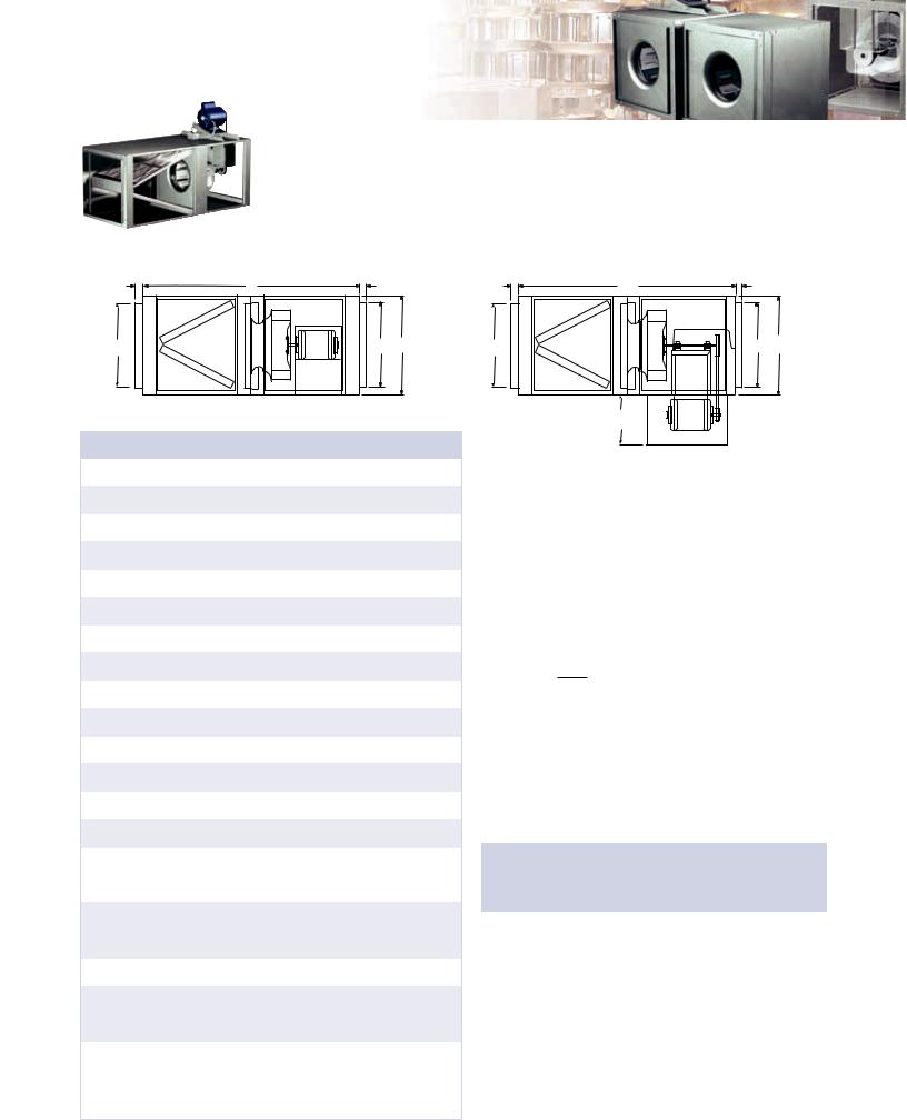
Filter Options
The filter box is designed to provide a compact and convenient clean air solution.
Factory assembled as a single unit, this fan eliminates the costly process of designing, fabricating, and installing special remote filter box assemblies. Both the fan and filter section feature removable access panels on both sides to remove and replace filters, making fan maintenance simple and fast.
|
Model SQ |
|
|
D |
A |
D |
|
C |
|
C |
B |
Model |
A |
B |
C |
D |
WT. |
Filter Size |
Filter |
|
Quantity |
||||||||
SQ-60 - 75 |
221⁄8 |
12 |
87⁄8 |
1 |
40 |
10 x 12 |
1 |
|
(562) |
(305) |
(225) |
(25) |
(18) |
(254 x 305) |
|||
|
|
|||||||
SQ-80 - 95 |
455⁄8 |
15 |
117⁄8 |
1 |
74 |
14 x 25 |
1 |
|
(1159) |
(381) |
(302) |
(25) |
(34) |
(356 x 635) |
|||
|
|
|||||||
SQ-100 |
471⁄4 |
17 |
137⁄8 |
1 |
88 |
16 x 20 |
2 |
|
(1200) |
(432) |
(352) |
(25) |
(40) |
(406 x 508) |
|||
|
|
|||||||
SQ-120 |
523⁄16 |
19 |
157⁄8 |
1 |
114 |
16 x 25 |
2 |
|
(1326) |
(483) |
(403) |
(25) |
(52) |
(406 x 635) |
|||
|
|
|||||||
SQ-130 |
463⁄8 |
21 |
177⁄8 |
1 |
120 |
20 x 20 |
2 |
|
(1178) |
(533) |
(454) |
(25) |
(54) |
(508 x 508) |
|||
|
|
|||||||
SQ-140 |
523⁄8 |
23 |
197⁄8 |
1 |
174 |
20 x 25 |
2 |
|
(1330) |
(584) |
(505) |
(25) |
(79) |
(508 x 635) |
|||
|
|
|||||||
SQ-160 |
513⁄8 |
26 |
227⁄8 |
1 |
246 |
20 x 20 |
4 |
|
(1305) |
(660) |
(581) |
(25) |
(112) |
(508 x 508) |
|||
|
|
|||||||
BSQ-70 - 80 - 90 |
505⁄8 |
15 |
117⁄8 |
1 |
117 |
14 x 25 |
1 |
|
|
(1286) |
(381) |
(302) |
(25) |
(53) |
(356 x 635) |
|
|
BSQ-100 |
471⁄4 |
17 |
137⁄8 |
1 |
120 |
16 x 20 |
2 |
|
(1200) |
(432) |
(352) |
(25) |
(54) |
(406 x 508) |
|||
|
|
|||||||
BSQ-120 |
523⁄16 |
19 |
157⁄8 |
1 |
144 |
16 x 25 |
2 |
|
(1326) |
(483) |
(403) |
(25) |
(79) |
(406 x 635) |
|||
|
|
|||||||
BSQ-130 - 130HP |
463⁄8 |
21 |
177⁄8 |
1 |
140 |
20 x 20 |
2 |
|
|
(1178) |
(533) |
(454) |
(25) |
(64) |
(508 x 508) |
|
|
BSQ-140 - 140HP |
523⁄8 |
23 |
197⁄8 |
1 |
181 |
20 x 25 |
2 |
|
|
(1330) |
(584) |
(505) |
(25) |
(82) |
(508 x 635) |
|
|
BSQ-160 - 160HP |
513⁄8 |
26 |
227⁄8 |
1 |
294 |
20 x 20 |
4 |
|
|
(1305) |
(660) |
(581) |
(25) |
(133) |
(508 x 508) |
|
|
BSQ-180 - 180HP |
551⁄16 |
28 |
237⁄8 |
11⁄2 |
344 |
20 x 25 |
4 |
|
|
(1399) |
(711) |
(606) |
(38) |
(156) |
(508 x 635) |
|
|
|
|
|
|
|
|
12 x 25 |
3 |
|
|
6611⁄16 |
32 |
277⁄8 |
11⁄2 |
441 |
(305 x 635) |
||
BSQ-200 - 200HP |
|
|||||||
(1694) |
(813) |
(708) |
(38) |
(200) |
16 x 25 |
3 |
||
|
||||||||
|
|
|
|
|
|
(406 x 635) |
||
|
|
|
|
|
|
|
||
|
|
|
|
|
|
20 x 25 |
4 |
|
|
687⁄8 |
39 |
347⁄8 |
11⁄2 |
573 |
(508 x 635) |
||
BSQ-240 - 240HP |
|
|||||||
(1749) |
(991) |
(886) |
(38) |
(260) |
16 x 25 |
4 |
||
|
||||||||
|
|
|
|
|
|
(406 x 635) |
||
|
|
|
|
|
|
|
||
BSQ-300 - 300HP |
721⁄8 |
46 |
417⁄8 |
11⁄2 |
759 |
20 x 25 |
8 |
|
|
(1832) |
(1168) |
(1064) |
(38) |
(344) |
(508 x 635) |
|
|
|
|
|
|
|
|
16 x 25 |
10 |
|
|
791⁄4 |
52 |
477⁄8 |
11⁄2 |
957 |
(406 x 635) |
||
BSQ-360 - 360HP |
|
|||||||
(2013) |
(1321) |
(1216) |
(38) |
(434) |
20 x 25 |
5 |
||
|
||||||||
|
|
|
|
|
|
(508 x 635) |
||
|
|
|
|
|
|
|
||
|
|
|
|
|
|
16 x 25 |
5 |
|
|
931⁄8 |
58 |
537⁄8 |
11⁄2 |
1185 |
(406 x 635) |
||
BSQ-420 |
|
|||||||
(2365) |
(1473) |
(1368) |
(38) |
(538) |
20 x 25 |
10 |
||
|
||||||||
|
|
|
|
|
|
(508 x 635) |
||
|
|
|
|
|
|
|
Note: 24-inch side clearance is recommended for accessing and removing filters. All dimensions in inches (millimeters) and weight (WT.) in pounds (kilograms).
|
Model BSQ |
|
|
D |
A |
D |
|
C |
|
C |
B |
|
Optional cover varies |
|
|
|
with motor size. |
|
|
|
Recommend 24 in. |
|
|
|
clearance. |
|
|
Model Selection Procedure
1.Calculate system pressure drop and CFM requirements (not including filters).
2.Make a preliminary model size selection.
3.Calculate a filter pressure drop for the preliminary model size selected in step 2 using the equation:
P = Fx ( 10,000cfm )2
4.Add the filter pressure drop (P) to the system pressure drop and make a revised model size selection. Use the charts on the left to determine filter factor (F).
Model Size |
1 in. |
|
1 in. |
|
2 in. |
|
2 in. |
|
|
|
|
Aluminum |
|
|
|
|
|||
|
|
|
Paper |
|
Aluminum |
|
Paper |
|
|
SQ |
BSQ |
Filter |
|
Filters |
|
Filters |
|
Filters |
|
Factor (F) |
|
|
|
|
|||||
|
|
|
|
|
|
||||
|
|
186 |
|
318.06 |
|
251.1 |
|
303.18 |
|
60-65-70-75 |
— |
|
|
|
|
||||
80-85-90-95 |
70-80-90 |
21.8 |
|
37.278 |
|
29.43 |
|
35.534 |
|
100 |
100 |
8.72 |
|
14.9112 |
|
11.772 |
|
14.2136 |
|
120 |
120 |
5.58 |
|
9.5418 |
|
7.533 |
|
9.0954 |
|
130 |
130 |
5.58 |
|
9.5418 |
|
7.533 |
|
9.0954 |
|
140 |
140 |
3.57 |
|
6.1047 |
|
4.8195 |
|
5.8191 |
|
160 |
160 |
2.09 |
|
3.5739 |
|
2.8215 |
|
3.4067 |
|
— |
180 |
1.34 |
|
2.2914 |
|
1.809 |
|
2.1842 |
|
— |
200 |
0.77 |
|
1.3167 |
|
1.0395 |
|
1.2551 |
|
— |
240 |
0.41 |
|
0.7011 |
|
0.5535 |
|
0.6683 |
|
— |
300 |
0.33 |
|
0.5643 |
|
0.4455 |
|
0.5379 |
|
— |
360 |
0.15 |
|
0.2565 |
|
0.2025 |
|
0.2445 |
|
— |
420 |
0.13 |
|
0.2223 |
|
0.1755 |
|
0.2119 |
|
8
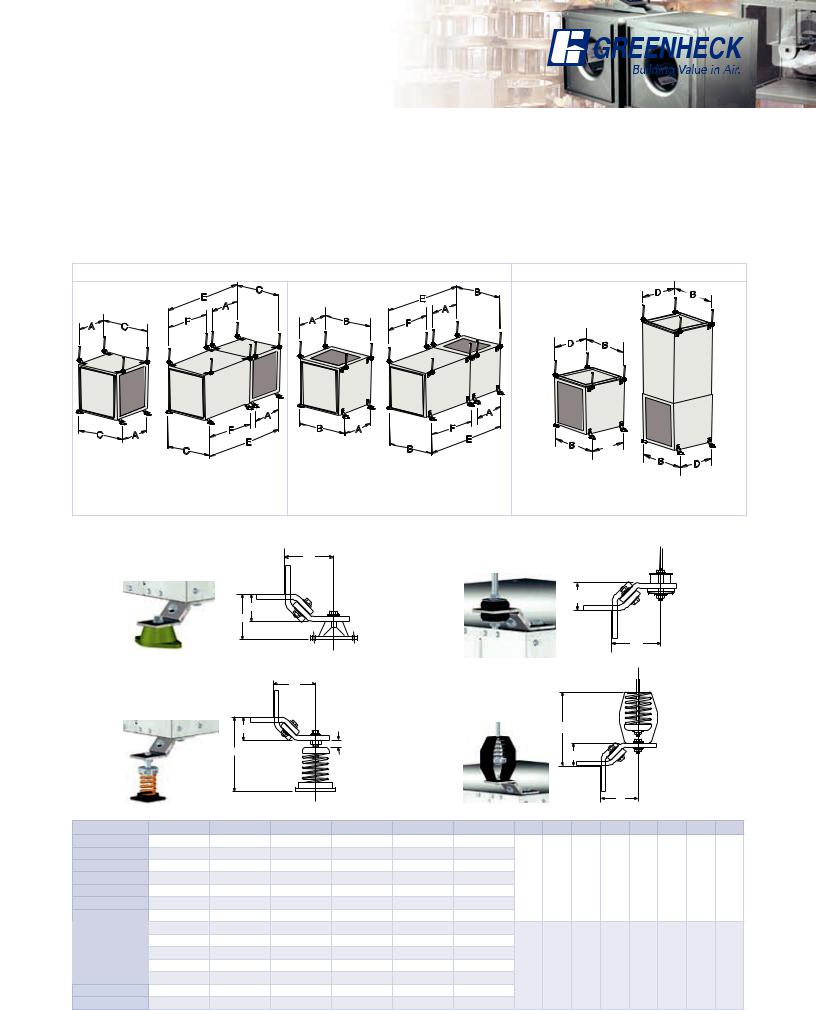
Horizontal and Vertical Mounting
Options
All model SQ and model BSQ fans can be mounted either horizontally or vertically. For ease of installation, knockouts are provided at each location where mounting brackets are shown in figures 6, 7, and 8. Optional brackets are universally adjustable to mount in any of these locations.
Complete isolator kits are available with either neoprene or spring isolators and are sized to match the weight of the individual fan sizes. The hanging isolator support brackets are designed to permit mounting of the fan with the motor located on top, bottom, or side. The hanging rods are to be supplied by others. The base isolator support brackets are designed to permit mounting of the fan with the motor located on top or either side.
|
|
|
Horizontal Hanging or Base Mount |
|
|
Vertical Hanging or Base Mount |
|||||
|
|
|
E |
C |
|
|
E |
B |
|
D |
B |
|
|
|
|
|
|
|
|
|
|||
|
|
|
A |
|
|
|
|
A |
|
|
|
|
|
|
|
|
|
|
|
|
|
|
|
A |
C |
|
F |
|
A |
B |
F |
|
|
|
|
|
|
|
|
|
|
|
|
|
D |
B |
|
|
|
|
|
A |
|
|
|
A |
|
|
|
|
|
|
|
|
|
|
|
|
|
|
|
C |
|
A |
F |
|
B |
A |
|
F |
|
|
|
|
|
E |
|
|
|
E |
B |
|
|
||
|
|
|
|
|
|
B |
|
|
|||
|
|
|
C |
|
|
|
|
|
|||
|
|
|
|
|
|
|
|
|
|||
Figure 6 |
|
|
|
|
|
|
|
B |
|
||
|
|
|
|
|
|
|
|
|
D |
||
With a hanging mount, the motor may be |
Figure 7 |
|
|
|
Figure 8 |
|
|||||
|
|
|
|
|
|||||||
located on either top or bottom. The base |
With either a hanging or base mount the |
Mounting brackets are turned 90° for vertical |
|||||||||
mount allows top motor location only. Both |
motor may be located on either side. The |
mounting. Access panels are located on the |
|||||||||
provide access panel on two sides. |
|
base mount allows top access panels only. |
two sides adjacent to mounting brackets. |
||||||||
Standing Neoprene Isolator |
|
|
|
Hanging Neoprene Isolator |
|
|
|
|
|||||||||
|
|
|
G |
|
|
|
|
|
|
|
|
|
|
|
|
|
|
|
|
|
|
|
|
|
|
|
|
|
H |
|
|
|
|
|
|
|
|
H |
|
|
|
|
|
|
|
|
|
|
|
|
|
|
|
|
|
N |
|
|
|
|
|
|
|
|
|
|
|
|
|
|
|
|
|
|
|
|
|
|
|
|
|
|
|
|
L |
|
|
|
|
Standing Spring Isolator |
J |
|
|
|
Hanging Spring Isolator |
|
|
|
|
|
|||||||
|
|
|
|
|
|
|
|
|
|
|
|
|
|
|
|
||
|
|
K |
|
|
|
|
|
|
|
M |
|
|
|
|
|
|
|
|
|
|
|
|
|
|
|
|
|
|
|
|
|
|
|
||
|
|
|
5/8 in. Nominal |
|
|
|
|
|
|
|
|
|
|
|
|
||
|
|
I |
|
|
|
|
|
|
|
|
K |
|
|
|
|
|
|
|
|
|
|
|
|
|
|
|
|
|
|
|
|
|
|
||
|
|
|
|
|
|
|
|
|
|
|
|
J |
|
|
|
|
|
Model |
A |
B |
C |
D |
E |
F |
|
G |
H |
I |
J |
K |
L |
M |
N |
||
SQ 60-75 |
105⁄8 (270) |
17 (432) |
153⁄4 (400) |
87⁄8 (225) |
193⁄4 (502) |
7 |
(178) |
|
|
|
|
|
|
|
|
||
SQ 80-95 |
131⁄4 (337) |
20 (508) |
183⁄4 (476) |
117⁄8 (302) |
43 |
(1092) |
273⁄8 (695) |
|
|
|
|
|
|
|
|
||
BSQ 70-90 |
185⁄8 (473) |
201⁄8 (511) |
183⁄4 (476) |
117⁄8 (302) |
485⁄16 (1227) |
273⁄8 (695) |
2 |
13⁄8 |
51⁄2 |
2 |
13⁄8 |
2 |
63⁄4 |
25⁄16 |
|||
SQ-BSQ 100 |
185⁄8 (473) |
221⁄8 (562) |
203⁄4 (527) |
137⁄8 (352) |
447⁄8 (1140) |
24 (610) |
|||||||||||
(51) |
(35) |
(140) |
(51) |
(35) |
(51) |
(171) |
(59) |
||||||||||
SQ-BSQ 120 |
185⁄8 (473) |
24 (610) |
223⁄4 (578) |
16 (406) |
493⁄8 (1254) |
281⁄8 (714) |
|||||||||||
SQ-BSQ 130 |
185⁄8 (473) |
261⁄8 (664) |
243⁄4 (629) |
177⁄8 (454) |
44 (1118) |
23 (584) |
|
|
|
|
|
|
|
|
|||
SQ-BSQ 140 |
195⁄8 (498) |
281⁄8 (714) |
263⁄4 (679) |
197⁄8 (505) |
501⁄16 (1272) |
28 (711) |
|
|
|
|
|
|
|
|
|||
SQ-BSQ 160 |
231⁄2 (597) |
31 (787) |
293⁄4 (756) |
227⁄8 (581) |
495⁄8 (1260) |
235⁄8 (600) |
|
|
|
|
|
|
|
|
|||
BSQ 180 |
251⁄2 (648) |
331⁄2 (851) |
299⁄16 (751) |
223⁄4 (578) |
529⁄16 (1335) |
241⁄2 (622) |
|
|
|
|
|
|
|
|
|||
BSQ 200 |
291⁄8 (740) |
37 (940) |
333⁄4 (857) |
263⁄4 (679) |
643⁄16 (1630) |
321⁄4 (819) |
2 |
13⁄8 |
51⁄2 |
2 |
13⁄8 |
2 |
63⁄4 |
25⁄8 |
|||
BSQ 240 |
315⁄8 (803) |
441⁄4 (1124) |
403⁄4 (1035) |
337⁄8 (860) |
661⁄2 (1689) |
321⁄8 (816) |
|||||||||||
(51) |
(35) |
(140) |
(51) |
(35) |
(51) |
(171) |
(67) |
||||||||||
BSQ 300 |
35 (889) |
51 (1295) |
473⁄4 (1213) |
407⁄8 (1038) |
691⁄8 (1756) |
313⁄8 (797) |
|||||||||||
BSQ 360 |
383⁄4 (974) |
571⁄4 (1454) |
531⁄2 (1359) |
463⁄4 (1187) |
76 (1930) |
3411⁄16 (881) |
|
|
|
|
|
|
|
|
|||
BSQ 420 |
471⁄8 (1197) |
63 (1600) |
597⁄8 (1521) |
597⁄8 (1521) |
901⁄2 (2299) |
401⁄2 (1029) |
|
|
|
|
|
|
|
|
|||
All dimensions in inches (millimeters).
9
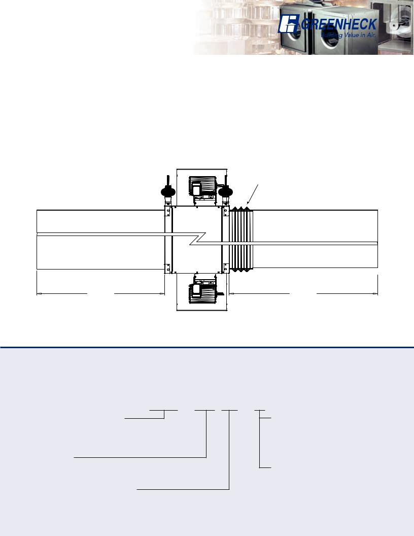
Typical Installation
Model BSQ ducted inline fans are designed for the exhaust, supply, or recirculation of air in a building. Typical installation requires ductwork on the inlet and outlet side of the fan. A minimum of three duct diameters is required on the inlet and outlet of the fan to prevent system effect losses. See the diagram below for a typical installation.
Installations can include flexible duct connections (by others) on either the inlet or outlet side of the fan or both. The motor is rigid mounted and can be oriented in any direction (top, bottom, side).
The model BSQ ducted inline fan must be installed with the motor accessible for maintenance and inspection.
External isolators are recommended, hanging (shown below) or base mounted. Installation must meet all local governing codes and the NEC.
Flexible duct (by others)
3 Wheel
Diameters
3 Wheel
Diameters
Model Number Code
The Model number system is designed to completely identify the fan. The correct code letters must be specified to designate belt or direct drive. The remainder of the model number is determined by the size and performance selected from the following pages.
BSQ - 240 HP - 7
Model Configuration
Bsq - Belt Drive Inline Exhaust
SQ - Direct Drive Inline Exhaust
Fan Size
60 through 420
Pressure Level (Belt Drive Only)
HP - High Pressure Wheel
Motor |
HP (Belt Drive only) |
|
|||
6 = 1/6 |
|
7 |
= 3/4 |
30 = |
3 |
4 = 1/4 |
|
10 |
= 1 |
50 = |
5 |
3 = 1/3 |
|
15 |
= 11⁄2 |
75 = |
71⁄2 |
5 = 1/2 |
|
20 |
= 2 |
100 = |
10 |
Motor RPM (Direct Drive only) |
|
||||
A = 1725 |
D = 1550 |
|
|||
B = 1140 |
E = 1050 |
|
|||
C = 860 |
|
G = 1300 |
|
||
10
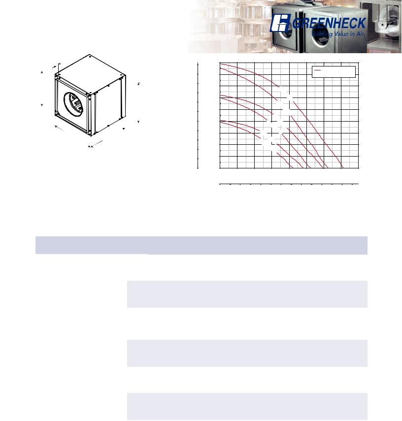
SQ 60-65 - Direct Drive
1
(25)
*87⁄8
(225)
12
(305)
12  13
13
(305) |
(330) |
Damper size = 9 x 9 (229 x 229) Unit weight** = 26 (12) Housing thickness = 20 ga Outlet velocity = 1.828 x cfm
Dimensions shown in inches (millimeters) and weight is shown in pounds (kilograms).
*May be greater depending on motor.
**Weight shown is largest cataloged Open Drip Proof motor.
Static Pressure Pa
110
100
90
80
70
60
50
40
30
20
10
0
|
0.45 |
|
|
|
|
|
|
|
|
|
|
|
|
|
|
|
|
|
|
|
|
|
|
|
|
RPM |
|
|
0.40 |
|
|
|
|
|
|
|
|
|
Density 0.075 lb/ft3 |
||
|
0.35 |
|
|
SQ- |
|
|
|
|
|
|
|
||
wg |
|
|
|
|
|
|
|
|
|
|
|||
|
|
|
|
|
60 |
|
|
|
|
|
|
||
|
|
|
|
|
|
- |
|
|
|
|
|||
in. |
0.30 |
|
|
|
|
|
|
D |
|
|
|
|
|
|
|
|
|
|
|
|
|
|
|
|
|
||
|
|
|
|
|
SQ |
|
|
|
|
||||
Pressure |
|
|
|
|
|
|
|
|
|
||||
|
|
|
|
|
|
|
- |
|
|
|
|
||
|
0.25 |
|
|
|
|
|
|
- |
|
|
|
|
|
|
|
|
|
|
|
|
65 |
|
|
|
|
||
|
|
|
|
|
|
|
|
|
- |
|
|
|
|
|
|
|
|
SQ- |
|
|
D |
|
|
|
|
||
|
0.20 |
|
|
|
|
|
|
|
|
|
|||
|
|
|
|
|
60 |
G |
|
|
|
|
|||
|
|
|
|
|
|
|
|
|
|
||||
Static |
|
|
|
|
SQ |
|
|
|
|
|
|
||
|
|
|
|
|
|
|
|
|
|
|
|||
0.15 |
|
|
|
|
- |
|
|
|
|
|
|||
|
|
|
|
|
|
65 |
|
|
|
|
|||
|
|
|
|
|
|
|
|
|
- |
|
|
|
|
|
|
|
SQ |
|
|
|
|
|
G |
|
|
|
|
|
|
|
|
|
SQ |
|
|
|
|
|
|
||
|
0.10 |
|
- |
|
|
- |
|
|
|
|
|||
|
|
|
65 |
E |
|
|
|
|
|||||
|
|
|
|
|
|
60- |
|
|
|
|
|||
|
|
|
|
- |
|
|
|
E |
|
|
|
|
|
|
|
|
|
|
|
|
|
|
|
|
|
|
|
|
0.05 |
|
|
|
|
|
|
|
|
|
|
|
|
|
0.000 |
|
50 |
|
|
100 |
150 |
|
200 |
250 |
|||
|
|
|
|
|
|
|
|
|
cfm |
|
|
|
|
|
0 |
50 |
100 |
|
150 |
|
|
200 |
250 |
300 |
350 |
400 |
|
|
|
|
|
|
|
|
|
|
m3/hr |
|
|
|
|
Model Number |
Motor |
Fan |
|
|
|
|
CFM / Static Pressure in Inches wg |
|
|
|
|||||
HP |
RPM |
|
0 |
0.05 |
0.1 |
|
0.125 |
0.15 |
0.2 |
0.25 |
|
0.3 |
0.35 |
0.375 |
|
|
|
|
|
||||||||||||
|
|
|
|
|
|
|
|
|
|
|
|
|
|
|
|
|
|
|
CFM |
126 |
101 |
78 |
|
63 |
42 |
|
|
|
|
|
|
|
|
|
|
|
|
|
|
|
|
|
|
|
|
|
|
SQ-60-E |
1/140 |
1050 |
BHP |
0.005 |
0.006 |
0.007 |
|
0.007 |
0.006 |
|
|
|
|
|
|
|
|
|
|
|
|
|
|
|
|
|
|
|
|
|
|
|
|
|
Sones |
1.7 |
1.7 |
1.8 |
|
1.8 |
1.9 |
|
|
|
|
|
|
|
|
|
|
|
|
|
|
|
|
|
|
|
|
|
|
|
|
|
CFM |
156 |
135 |
117 |
|
109 |
99 |
72 |
37 |
|
|
|
|
|
|
|
|
|
|
|
|
|
|
|
|
|
|
|
|
SQ-60-G |
1/80 |
1300 |
BHP |
0.01 |
0.011 |
0.012 |
|
0.012 |
0.013 |
0.013 |
0.012 |
|
|
|
|
|
|
|
|
|
|
|
|
|
|
|
|
|
|
|
|
|
|
|
Sones |
2.5 |
2.5 |
2.5 |
|
2.5 |
2.5 |
2.5 |
2.5 |
|
|
|
|
|
|
|
|
|
|
|
|
|
|
|
|
|
|
|
|
|
|
|
CFM |
186 |
168 |
153 |
|
145 |
138 |
122 |
105 |
|
78 |
47 |
31 |
|
|
|
|
|
|
|
|
|
|
|
|
|
|
|
|
SQ-60-D |
1/40 |
1550 |
BHP |
0.017 |
0.018 |
0.019 |
|
0.02 |
0.02 |
0.022 |
0.022 |
|
0.021 |
0.02 |
0.019 |
|
|
|
|
|
|
|
|
|
|
|
|
|
|
|
|
|
|
|
Sones |
4.0 |
4.0 |
4.0 |
|
4.0 |
4.0 |
4.0 |
4.0 |
|
4.1 |
4.1 |
4.1 |
|
|
|
|
|
|
|
|
|
|
|
|
|
|
|
|
|
|
|
|
|
|
|
|
|
|
|
|
|
|
|
|
|
|
|
CFM |
154 |
129 |
98 |
|
79 |
56 |
|
|
|
|
|
|
|
|
|
|
|
|
|
|
|
|
|
|
|
|
|
|
SQ-65-E |
1/100 |
1050 |
BHP |
0.007 |
0.008 |
0.009 |
|
0.009 |
0.008 |
|
|
|
|
|
|
|
|
|
|
|
|
|
|
|
|
|
|
|
|
|
|
|
|
|
Sones |
2.1 |
2.0 |
2.0 |
|
1.9 |
1.9 |
|
|
|
|
|
|
|
|
|
|
|
|
|
|
|
|
|
|
|
|
|
|
|
|
|
CFM |
191 |
171 |
149 |
|
137 |
123 |
92 |
52 |
|
|
|
|
|
|
|
|
|
|
|
|
|
|
|
|
|
|
|
|
SQ-65-G |
1/50 |
1300 |
BHP |
0.013 |
0.014 |
0.016 |
|
0.016 |
0.017 |
0.016 |
0.015 |
|
|
|
|
|
|
|
|
|
|
|
|
|
|
|
|
|
|
|
|
|
|
|
Sones |
2.9 |
2.9 |
2.9 |
|
2.9 |
2.9 |
2.8 |
2.8 |
|
|
|
|
|
|
|
|
|
|
|
|
|
|
|
|
|
|
|
|
|
|
|
CFM |
228 |
213 |
194 |
|
184 |
175 |
153 |
128 |
|
101 |
66 |
46 |
|
|
|
|
|
|
|
|
|
|
|
|
|
|
|
|
SQ-65-D |
1/30 |
1550 |
BHP |
0.022 |
0.023 |
0.026 |
|
0.026 |
0.027 |
0.028 |
0.028 |
|
0.027 |
0.025 |
0.023 |
|
|
|
|
|
|
|
|
|
|
|
|
|
|
|
|
|
|
|
Sones |
4.2 |
4.1 |
4.1 |
|
4.0 |
4.0 |
3.9 |
3.8 |
|
3.7 |
3.6 |
3.5 |
|
|
|
|
|
|
|
|
|
|
|
|
|
|
|
|
Performance certified is for installation type B: Free inlet, Ducted outlet. Performance ratings do not include the effects of appurtenances (accessories).
The sound ratings shown are loudness values in fan sones at 1.5 m (5 feet) in a hemispherical free field calculated per AMCA Standard 301. Values shown are for installation type B: free inlet hemispherical fan sone levels.
11
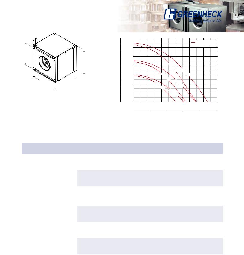
SQ 70-75 - Direct Drive
1
(25)
*87⁄8
(225)
12
(305)
12 |
13 |
(305) (330)
(330)
Damper size = 9 x 9 (229 x 229) Unit weight** = 26 (12) Housing thickness = 20 ga Outlet velocity = 1.828 x cfm
Dimensions shown in inches (millimeters) and weight is shown in pounds (kilograms).
*May be greater depending on motor.
**Weight shown is largest cataloged Open Drip Proof motor.
Static Pressure Pa
110
100
90
80
70
60
50
40
30
20
10
0
|
0.45 |
|
|
|
|
|
|
|
|
|
|
|
|
|
|
|
|
|
|
|
|
|
RPM |
|
|
|
0.40 |
|
|
|
|
|
|
|
|
Density 0.075 lb/ft3 |
|
|
|
0.35 |
|
|
|
|
|
SQ |
|
|
|
|
|
wg |
|
|
|
|
|
|
|
|
|
|
||
|
|
|
|
|
|
|
- |
|
|
|
|
|
|
0.30 |
|
|
|
|
|
|
70 |
|
|
|
|
|
|
|
|
|
|
|
D |
|
|
|
|
|
in. |
|
|
|
|
|
|
|
- |
|
|
|
|
|
|
|
|
|
|
SQ |
|
|
|
|
||
Pressure |
|
|
|
|
|
|
|
|
|
|
||
0.25 |
|
|
|
|
|
|
- |
|
|
|
|
|
|
|
|
|
|
|
- |
|
|
|
|
||
|
|
|
|
|
|
|
75- |
|
|
|
|
|
|
|
|
|
|
|
|
|
D |
|
|
|
|
|
|
|
|
|
|
SQ |
|
|
|
|
|
|
|
0.20 |
|
|
|
|
|
- |
|
|
|
|
|
|
|
|
|
SQ |
70 |
|
|
|
|
|||
|
|
|
|
|
|
G |
|
|
|
|
||
Static |
|
|
|
|
|
- |
|
|
|
|
|
|
|
|
|
|
70 |
75 |
|
|
|
|
|
||
|
|
|
|
|
- |
|
|
|
|
|
||
|
0.15 |
|
|
SQ- |
|
|
|
|
|
|
||
|
|
|
|
G |
|
|
|
|
||||
|
|
|
|
|
|
|
|
|
|
|
||
|
|
|
|
|
- |
|
|
|
|
|
|
|
|
0.10 |
|
|
SQ |
|
E |
|
|
|
|
|
|
|
|
|
|
|
|
|
|
|
|
|
||
|
|
|
- |
|
|
|
|
|
|
|
||
|
|
|
|
|
75 |
|
|
|
|
|
|
|
|
|
|
|
|
- |
|
|
|
|
|
|
|
|
|
|
|
|
|
E |
|
|
|
|
|
|
|
0.05 |
|
|
|
|
|
|
|
|
|
|
|
|
0.000 |
50 |
100 |
|
150 |
|
200 |
250 |
300 |
350 |
400 |
|
|
|
|
|
|
|
|
|
cfm |
|
|
|
|
|
0 |
100 |
200 |
|
|
300 |
400 |
500 |
600 |
|
||
|
|
|
|
|
|
|
|
m3/hr |
|
|
|
|
Model Number |
Motor |
Fan |
|
|
|
|
CFM / Static Pressure in Inches wg |
|
|
|
|||||
HP |
RPM |
|
0 |
0.1 |
0.125 |
|
0.15 |
0.2 |
0.25 |
0.3 |
|
0.35 |
0.375 |
0.4 |
|
|
|
|
|
||||||||||||
|
|
|
|
|
|
|
|
|
|
|
|
|
|
|
|
|
|
|
CFM |
212 |
140 |
118 |
|
86 |
|
|
|
|
|
|
|
|
|
|
|
|
|
|
|
|
|
|
|
|
|
|
|
SQ-70-E |
1/100 |
1050 |
BHP |
0.008 |
0.009 |
0.009 |
|
0.009 |
|
|
|
|
|
|
|
|
|
|
Sones |
2.7 |
1.7 |
1.5 |
|
1.5 |
|
|
|
|
|
|
|
|
|
|
|
|
|
|
|
|
|
|
|
|
|
|
|
|
|
|
CFM |
262 |
204 |
190 |
|
176 |
139 |
77 |
|
|
|
|
|
|
|
|
|
|
|
|
|
|
|
|
|
|
|
|
|
SQ-70-G |
1/50 |
1300 |
BHP |
0.015 |
0.018 |
0.018 |
|
0.018 |
0.017 |
0.015 |
|
|
|
|
|
|
|
|
Sones |
4.1 |
3.4 |
3.3 |
|
3.1 |
2.9 |
2.5 |
|
|
|
|
|
|
|
|
|
|
|
|
|
|
|
|
|
|
|
|
|
|
|
|
CFM |
313 |
265 |
252 |
|
240 |
216 |
189 |
155 |
|
99 |
67 |
|
|
|
|
|
|
|
|
|
|
|
|
|
|
|
|
|
SQ-70-D |
1/30 |
1550 |
BHP |
0.026 |
0.029 |
0.03 |
|
0.03 |
0.03 |
0.03 |
0.029 |
|
0.026 |
0.025 |
|
|
|
|
Sones |
5.6 |
5.2 |
5.1 |
|
5.1 |
4.9 |
4.7 |
4.5 |
|
4.2 |
4.0 |
|
|
|
|
|
|
|
|
|
|
|
|
|
|
|
|
|
|
|
|
|
|
|
|
|
|
|
|
|
|
|
|
|
|
|
|
CFM |
241 |
167 |
146 |
|
123 |
|
|
|
|
|
|
|
|
|
|
|
|
|
|
|
|
|
|
|
|
|
|
|
SQ-75-E |
1/100 |
1050 |
BHP |
0.01 |
0.011 |
0.011 |
|
0.01 |
|
|
|
|
|
|
|
|
|
|
Sones |
3.6 |
2.9 |
2.8 |
|
2.6 |
|
|
|
|
|
|
|
|
|
|
|
|
|
|
|
|
|
|
|
|
|
|
|
|
|
|
CFM |
298 |
239 |
224 |
|
209 |
176 |
133 |
|
|
|
|
|
|
|
|
|
|
|
|
|
|
|
|
|
|
|
|
|
SQ-75-G |
1/50 |
1300 |
BHP |
0.019 |
0.021 |
0.021 |
|
0.021 |
0.02 |
0.019 |
|
|
|
|
|
|
|
|
Sones |
4.1 |
3.7 |
3.7 |
|
3.7 |
3.6 |
3.5 |
|
|
|
|
|
|
|
|
|
|
|
|
|
|
|
|
|
|
|
|
|
|
|
|
CFM |
356 |
306 |
294 |
|
281 |
256 |
229 |
201 |
|
164 |
137 |
99 |
|
|
|
|
|
|
|
|
|
|
|
|
|
|
|
|
SQ-75-D |
1/30 |
1550 |
BHP |
0.032 |
0.034 |
0.035 |
|
0.035 |
0.035 |
0.035 |
0.034 |
|
0.033 |
0.032 |
0.029 |
|
|
|
Sones |
6.1 |
5.5 |
5.4 |
|
5.3 |
5.1 |
4.9 |
4.9 |
|
4.8 |
4.8 |
4.8 |
|
|
|
|
|
|
|
|
|
|
|
|
|
|
|
|
Performance certified is for installation type B: Free inlet, Ducted outlet. Performance ratings do not include the effects of appurtenances (accessories).
The sound ratings shown are loudness values in fan sones at 1.5 m (5 feet) in a hemispherical free field calculated per AMCA Standard 301. Values shown are for installation type B: free inlet hemispherical fan sone levels.
12
SQ 80-85 - Direct Drive
1
(25)
*117⁄8
(302)
15
(381)
15 |
16 |
(381) (406)
(406)
Damper size = 12 x 12 (305 x 305) Unit weight** = 41 (19)
Housing thickness = 20 ga Outlet velocity = 1.021 x cfm
Dimensions shown in inches (millimeters) and weight is shown in pounds (kilograms).
*May be greater depending on motor.
**Weight shown is largest cataloged Open Drip Proof motor.
Static Pressure Pa
|
|
0.7 |
|
|
|
|
|
|
|
160 |
|
|
|
|
|
|
|
RPM |
|
|
0.6 |
|
|
|
|
Density 0.075 lb/ft3 |
|||
|
|
|
|
|
|
|
|
|
|
140 |
|
|
|
|
|
|
|
|
|
120 |
wg |
0.5 |
|
|
|
|
|
|
|
|
|
|
|
|
|
|
|
||
|
in. |
|
|
SQ |
|
|
|
||
100 |
Pressure |
0.4 |
|
|
|
|
|||
|
- |
|
- |
|
|
|
|||
|
|
|
|
80 |
|
|
|
||
|
|
|
|
|
|
- |
SQ |
|
|
|
|
|
|
|
|
D |
|
|
|
|
|
|
|
|
|
- |
|
|
|
80 |
|
|
|
|
|
|
|
|
|
|
0.3 |
|
SQ |
|
|
85 |
|
|
|
|
|
|
|
|
D |
|
|
||
|
|
|
|
|
|
|
- |
|
|
|
Static |
0.2 |
|
80 |
|
85 |
|
|
|
|
|
SQ |
|
|
|
||||
|
|
|
|
- |
|
|
|
|
|
60 |
|
|
|
G |
SQ |
|
|
|
|
|
|
|
|
|
|
|
|
||
|
|
|
|
|
|
- |
- |
|
|
|
|
|
|
- |
|
|
|
|
|
40 |
|
|
|
80 |
|
|
G |
|
|
|
|
|
- |
|
|
|
|
|
|
|
|
|
|
E |
SQ |
|
|
|
|
|
|
|
|
|
|
|
|
||
|
|
0.1 |
|
|
|
- |
|
|
|
20 |
|
|
|
|
85 |
|
|
|
|
|
|
|
|
|
E |
|
|
|
|
|
|
|
|
|
|
- |
|
|
|
0 |
|
0.00 |
100 |
200 |
|
300 |
400 |
500 |
600 |
|
|
|
|
|
|
cfm |
|
|
|
|
|
0 |
200 |
400 |
|
|
600 |
800 |
1000 |
|
|
|
|
|
|
m3/hr |
|
|
|
Model Number |
Motor |
Fan |
|
|
|
|
CFM / Static Pressure in Inches wg |
|
|
|
|||||
HP |
RPM |
|
0 |
0.1 |
0.125 |
|
0.2 |
0.25 |
0.3 |
0.375 |
|
0.4 |
0.45 |
0.5 |
|
|
|
|
|
||||||||||||
|
|
|
|
|
|
|
|
|
|
|
|
|
|
|
|
|
|
|
CFM |
306 |
241 |
225 |
|
166 |
104 |
|
|
|
|
|
|
|
|
|
|
|
|
|
|
|
|
|
|
|
|
|
|
SQ-80-E |
1/40 |
1050 |
BHP |
0.011 |
0.014 |
0.015 |
|
0.017 |
0.016 |
|
|
|
|
|
|
|
|
|
|
|
|
|
|
|
|
|
|
|
|
|
|
|
|
|
Sones |
3.8 |
3.7 |
3.6 |
|
3.8 |
4.1 |
|
|
|
|
|
|
|
|
|
|
|
|
|
|
|
|
|
|
|
|
|
|
|
|
|
CFM |
378 |
324 |
312 |
|
273 |
244 |
210 |
140 |
|
|
|
|
|
|
|
|
|
|
|
|
|
|
|
|
|
|
|
|
SQ-80-G |
1/20 |
1300 |
BHP |
0.021 |
0.025 |
0.026 |
|
0.029 |
0.032 |
0.032 |
0.031 |
|
|
|
|
|
|
|
|
|
|
|
|
|
|
|
|
|
|
|
|
|
|
|
Sones |
5.4 |
5.4 |
5.4 |
|
5.4 |
5.4 |
5.4 |
5.5 |
|
|
|
|
|
|
|
|
|
|
|
|
|
|
|
|
|
|
|
|
|
|
|
CFM |
451 |
405 |
394 |
|
363 |
342 |
318 |
280 |
|
266 |
238 |
201 |
|
|
|
|
|
|
|
|
|
|
|
|
|
|
|
|
SQ-80-D |
1/12 |
1550 |
BHP |
0.035 |
0.039 |
0.041 |
|
0.045 |
0.047 |
0.051 |
0.055 |
|
0.055 |
0.055 |
0.055 |
|
|
|
|
|
|
|
|
|
|
|
|
|
|
|
|
|
|
|
Sones |
7.3 |
7.3 |
7.3 |
|
7.3 |
7.2 |
7.3 |
7.3 |
|
7.4 |
7.5 |
7.6 |
|
|
|
|
|
|
|
|
|
|
|
|
|
|
|
|
|
|
|
|
|
|
|
|
|
|
|
|
|
|
|
|
|
|
|
CFM |
357 |
291 |
272 |
|
206 |
142 |
|
|
|
|
|
|
|
|
|
|
|
|
|
|
|
|
|
|
|
|
|
|
SQ-85-E |
1/40 |
1050 |
BHP |
0.012 |
0.016 |
0.017 |
|
0.018 |
0.017 |
|
|
|
|
|
|
|
|
|
|
|
|
|
|
|
|
|
|
|
|
|
|
|
|
|
Sones |
4.0 |
3.9 |
3.9 |
|
3.9 |
4.0 |
|
|
|
|
|
|
|
|
|
|
|
|
|
|
|
|
|
|
|
|
|
|
|
|
|
CFM |
442 |
391 |
377 |
|
331 |
298 |
260 |
185 |
|
|
|
|
|
|
|
|
|
|
|
|
|
|
|
|
|
|
|
|
SQ-85-G |
1/20 |
1300 |
BHP |
0.024 |
0.028 |
0.028 |
|
0.032 |
0.033 |
0.034 |
0.033 |
|
|
|
|
|
|
|
|
|
|
|
|
|
|
|
|
|
|
|
|
|
|
|
Sones |
5.5 |
5.3 |
5.3 |
|
5.3 |
5.3 |
5.4 |
5.4 |
|
|
|
|
|
|
|
|
|
|
|
|
|
|
|
|
|
|
|
|
|
|
|
CFM |
528 |
485 |
474 |
|
439 |
413 |
386 |
343 |
|
327 |
294 |
254 |
|
|
|
|
|
|
|
|
|
|
|
|
|
|
|
|
SQ-85-D |
1/12 |
1550 |
BHP |
0.04 |
0.045 |
0.046 |
|
0.049 |
0.052 |
0.054 |
0.056 |
|
0.057 |
0.057 |
0.057 |
|
|
|
|
|
|
|
|
|
|
|
|
|
|
|
|
|
|
|
Sones |
7.6 |
7.4 |
7.4 |
|
7.4 |
7.4 |
7.4 |
7.4 |
|
7.5 |
7.5 |
7.6 |
|
|
|
|
|
|
|
|
|
|
|
|
|
|
|
|
Performance certified is for installation type B: Free inlet, Ducted outlet. Performance ratings do not include the effects of appurtenances (accessories).
The sound ratings shown are loudness values in fan sones at 1.5 m (5 feet) in a hemispherical free field calculated per AMCA Standard 301. Values shown are for installation type B: free inlet hemispherical fan sone levels.
13

SQ 90-95 - Direct Drive
1
(25)
*117⁄8
(302)
15
(381)
15 |
16 |
(381) (406)
(406)
Damper size = 12 x 12 (305 x 305) Unit weight** = 41 (19)
Housing thickness = 20 ga Outlet velocity = 1.021 x cfm
Dimensions shown in inches (millimeters) and weight is shown in pounds (kilograms).
*May be greater depending on motor.
**Weight shown is largest cataloged Open Drip Proof motor.
Static Pressure Pa
|
|
0.8 |
|
|
|
|
|
|
|
|
|
|
|
|
|
|
|
180 |
|
|
|
|
|
|
|
|
|
|
|
|
|
|
RPM |
|
|
|
0.7 |
|
|
|
|
|
|
|
|
|
|
|
Density 0.075 lb/ft3 |
|
|||
160 |
|
|
|
|
|
|
|
|
|
|
|
|
|
|
|
|
|
|
wg |
0.6 |
|
SQ |
|
|
|
|
SQ |
|
|
|
|
|
|
|
|
140 |
|
|
|
|
|
|
|
|
|
|
|
|
|
||||
|
|
|
|
|
- |
|
|
|
- |
|
|
|
|
|
|
||
|
|
|
|
|
|
95 |
|
|
|
90 |
|
|
|
|
|
||
|
in. |
0.5 |
|
|
|
|
- |
|
|
|
- |
|
|
|
|
|
|
120 |
|
|
|
|
|
D |
|
|
|
D |
|
|
|
|
|
||
|
|
|
|
|
|
|
|
|
|
|
|
|
|
|
|
||
Pressure |
|
|
|
|
|
|
|
|
|
|
|
|
|
|
|
|
|
100 |
0.4 |
|
SQ |
|
SQ |
|
|
|
|
|
|
|
|
||||
|
|
|
|
|
|
|
|
|
|
|
|||||||
|
|
|
|
|
|
|
|
|
|
|
|
|
|||||
|
|
|
|
|
|
- |
|
|
- |
|
|
|
|
|
|
|
|
|
|
|
|
|
|
|
|
|
90 |
|
|
|
|
|
|
|
|
|
|
|
|
|
|
95 |
|
- |
|
|
|
|
|
|
|
||
80 |
|
|
|
|
|
|
G |
|
|
|
|
|
|
||||
|
|
|
|
|
|
|
- |
|
|
|
|
|
|
|
|
|
|
|
Static |
0.3 |
|
|
|
|
|
G |
|
|
|
|
|
|
|
|
|
|
|
|
|
|
|
|
|
|
|
|
|
|
|
|
|
||
60 |
|
|
SQ- |
|
SQ- |
|
|
|
|
|
|
|
|||||
|
|
|
|
|
|
|
|
|
|
|
|||||||
|
|
0.2 |
|
|
|
|
|
|
|
|
|
||||||
40 |
|
|
|
|
|
95- |
|
90- |
|
|
|
|
|
|
|||
|
|
|
|
|
|
E |
|
E |
|
|
|
|
|
|
|||
20 |
|
0.1 |
|
|
|
|
|
|
|
|
|
|
|
|
|
|
|
|
|
|
|
|
|
|
|
|
|
|
|
|
|
|
|
|
|
0 |
|
0.00 |
100 |
200 |
|
300 |
|
400 |
500 |
600 |
700 |
800 |
900 |
1000 |
|||
|
|
|
|
|
|
|
|
|
|
|
|
cfm |
|
|
|
|
|
|
|
0 |
200 |
400 |
|
|
|
600 |
|
800 |
1000 |
1200 |
1400 |
1600 |
|||
|
|
|
|
|
|
|
|
|
|
|
|
m3/hr |
|
|
|
|
|
Model Number |
Motor |
Fan |
|
|
|
|
CFM / Static Pressure in Inches wg |
|
|
|
|||||
HP |
RPM |
|
0 |
0.125 |
0.2 |
|
0.25 |
0.3 |
0.375 |
0.4 |
|
0.5 |
0.6 |
0.625 |
|
|
|
|
|
||||||||||||
|
|
|
|
|
|
|
|
|
|
|
|
|
|
|
|
|
|
|
CFM |
500 |
369 |
271 |
|
188 |
|
|
|
|
|
|
|
|
|
|
|
|
|
|
|
|
|
|
|
|
|
|
|
SQ-90-E |
1/50 |
1050 |
BHP |
0.016 |
0.02 |
0.021 |
|
0.02 |
|
|
|
|
|
|
|
|
|
|
Sones |
4.0 |
3.9 |
4.0 |
|
4.1 |
|
|
|
|
|
|
|
|
|
|
|
|
|
|
|
|
|
|
|
|
|
|
|
|
|
|
CFM |
619 |
519 |
449 |
|
397 |
343 |
245 |
207 |
|
|
|
|
|
|
|
|
|
|
|
|
|
|
|
|
|
|
|
|
SQ-90-G |
1/25 |
1300 |
BHP |
0.03 |
0.036 |
0.039 |
|
0.04 |
0.04 |
0.038 |
0.037 |
|
|
|
|
|
|
|
Sones |
5.4 |
5.4 |
5.4 |
|
5.5 |
5.5 |
5.6 |
5.6 |
|
|
|
|
|
|
|
|
|
|
|
|
|
|
|
|
|
|
|
|
|
|
|
CFM |
738 |
654 |
602 |
|
564 |
522 |
457 |
435 |
|
334 |
|
|
|
|
|
|
|
|
|
|
|
|
|
|
|
|
|
|
SQ-90-D |
1/10 |
1550 |
BHP |
0.051 |
0.059 |
0.062 |
|
0.064 |
0.067 |
0.068 |
0.068 |
|
0.067 |
|
|
|
|
|
Sones |
7.6 |
7.5 |
7.5 |
|
7.4 |
7.4 |
7.4 |
7.4 |
|
7.4 |
|
|
|
|
|
|
|
|
|
|
|
|
|
|
|
|
|
|
|
|
|
|
|
|
|
|
|
|
|
|
|
|
|
|
|
|
|
CFM |
623 |
475 |
365 |
|
274 |
|
|
|
|
|
|
|
|
|
|
|
|
|
|
|
|
|
|
|
|
|
|
|
SQ-95-E |
1/30 |
1050 |
BHP |
0.028 |
0.031 |
0.031 |
|
0.03 |
|
|
|
|
|
|
|
|
|
|
Sones |
4.9 |
4.5 |
4.4 |
|
4.5 |
|
|
|
|
|
|
|
|
|
|
|
|
|
|
|
|
|
|
|
|
|
|
|
|
|
|
CFM |
771 |
659 |
579 |
|
522 |
461 |
352 |
311 |
|
|
|
|
|
|
|
|
|
|
|
|
|
|
|
|
|
|
|
|
SQ-95-G |
1/15 |
1300 |
BHP |
0.053 |
0.057 |
0.058 |
|
0.059 |
0.059 |
0.057 |
0.056 |
|
|
|
|
|
|
|
Sones |
7.6 |
6.7 |
6.5 |
|
6.4 |
6.4 |
6.4 |
6.4 |
|
|
|
|
|
|
|
|
|
|
|
|
|
|
|
|
|
|
|
|
|
|
|
CFM |
919 |
829 |
765 |
|
720 |
677 |
603 |
579 |
|
461 |
324 |
276 |
|
|
|
|
|
|
|
|
|
|
|
|
|
|
|
|
SQ-95-D |
1/8 |
1550 |
BHP |
0.09 |
0.094 |
0.097 |
|
0.097 |
0.1 |
0.1 |
0.1 |
|
0.099 |
0.094 |
0.091 |
|
|
|
Sones |
9.6 |
9.3 |
8.9 |
|
8.7 |
8.4 |
8.1 |
8.0 |
|
7.6 |
7.2 |
7.1 |
|
|
|
|
|
|
|
|
|
|
|
|
|
|
|
|
Performance certified is for installation type B: Free inlet, Ducted outlet. Performance ratings do not include the effects of appurtenances (accessories).
The sound ratings shown are loudness values in fan sones at 1.5 m (5 feet) in a hemispherical free field calculated per AMCA Standard 301. Values shown are for installation type B: free inlet hemispherical fan sone levels.
14
 Loading...