


Centrifugal Inline Fans
Models SQ and BSQ
Direct and Belt Drive
®
April
2012
Models SQ and BSQ
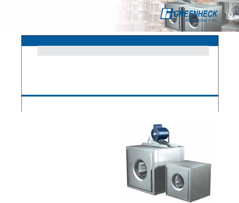
Centrifugal Square Inline Duct Fans
Table of Contents
Standard Construction Features . . . |
. |
|
4-5 |
Typical Installation . . . . . . . . . . 14 |
|||||
Vari-Green Motor & Control Options . |
. |
|
6-7 |
Model Number Code . |
|
. . . . . . . . 14 |
|||
Options and Accessories . . . . . |
. |
. |
.8 |
Direct Drive . . . . . . . . . . . 15-23 |
|||||
Filter Options . . . . . . . . . . . . .9 |
Belt Drive . . |
. . . |
. . . . . . . 24-45 |
||||||
Discharge Configurations . . . . . |
. 10-11 |
Specifications |
. . . |
. . . . . . . 46-47 |
|||||
Mounting Options . . . . . . . . |
. |
. |
12 |
Quick Delivery |
. . . |
. |
. . |
. . |
. . . .48 |
Isolators . . . . . . . . . . . . |
. |
. |
13 |
Warranty . . |
. . . |
. |
. . |
. . |
. . . .48 |
Greenheck Fan Corporation certifies the model SQ and BSQ fans shown herein are licensed to bear the AMCA Seal. The ratings shown are based on tests and procedures performed in accordance with AMCA Publication 211 and Publication 311 and comply with the requirements of the AMCA Certified Ratings Program. The certified ratings for models SQ and BSQ are shown on pages 15 to 45.
UL is optional and must be specified. SQ and BSQ models are Listed for Electrical (UL/cUL 705) File no. E40001
2
Models SQ and BSQ
Centrifugal Square Inline Duct Fans
Model Comparison
|
Location |
|
Mounting |
|
|
Airflow |
|
|
|
Application |
|
|
Drive |
Impeller |
Performance |
|
|||||||||||
|
|
|
|
|
|
|
|
|
Type |
|
Type |
|
|
||||||||||||||
|
|
|
|
|
|
|
|
|
|
|
|
|
|
|
|
|
|
|
|
|
|
|
|
||||
|
|
|
|
|
|
|
|
|
|
|
|
|
|
|
|
|
|
|
|
|
|
|
|
|
|
|
CostRelative |
Model |
Outdoor |
Indoor |
CurbRoof |
Base/Floor |
Hanging |
Wall |
MountedCeiling |
Exhaust |
Supply |
Reversible |
Recirculate |
AirGeneral/Clean |
AirContaminated |
ResistantSpark |
762)(ULGrease |
ControlSmoke(UL) |
(150WindHighmph) |
(aboveTempHigh200°F ) |
Belt |
Direct |
Centrifugal |
Propeller/Axial |
|
FlowMixed |
VolumeMaximum (cfm) |
StaticMaximumPressure wg)(in. |
|
|
|
|
|
|
|
|
|
|
|
|
|
|
|
|
|
|
|
|
|
|
|
|
|
|
|
|
|
|
|
|
|
|
|
|
|
|
|
|
|
|
|
|
|
|
|
|
|
|
|
|
|
|
|
|
|
SQ |
|
|
|
|
|
|
|
|
|
|
|
|
|
|
|
|
|
|
|
|
|
|
|
5,000 |
2 |
$ |
|
|
|
|
|
|
|
|
|
|
|
|
|
|
|
|
|
|
|
|
|
|
|
|
|
|
|
BSQ |
|
|
|
|
|
|
|
|
|
|
|
|
|
|
|
|
|
|
|
|
|
|
|
27,200 |
4 |
$ |
|
|
|
|
|
|
|
|
|
|
|
|
|
|
|
|
|
|
|
|
|
|
|
|
|
|
|
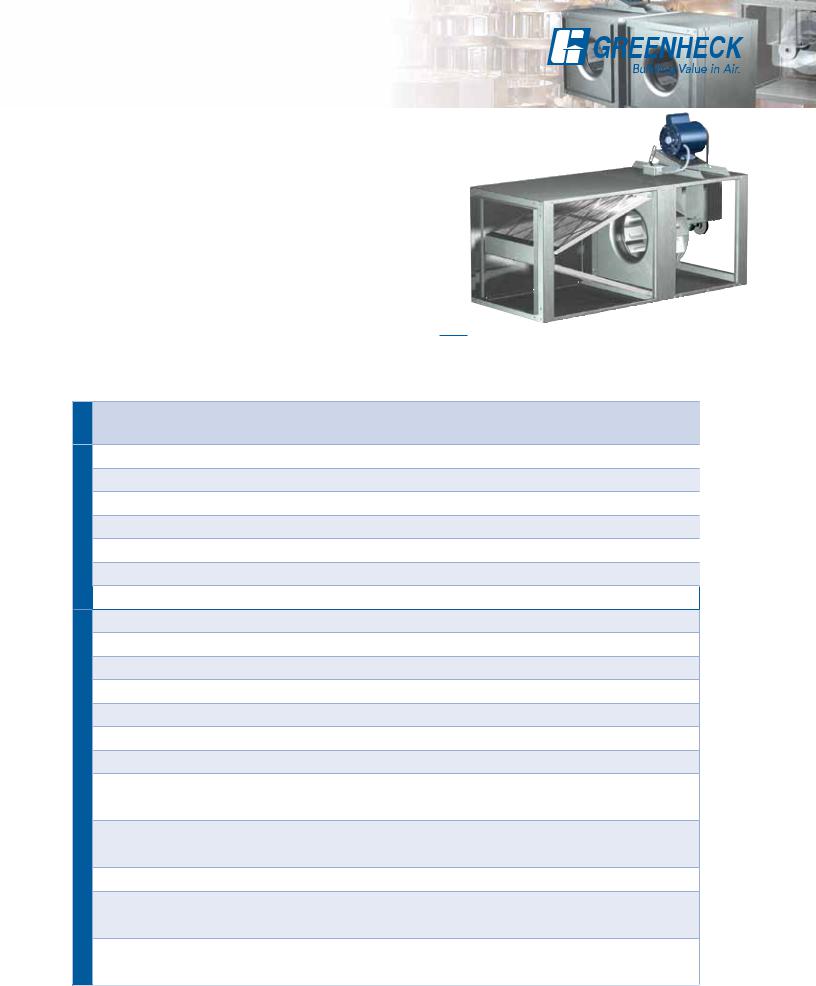
Greenheck’s model SQ and BSQ centrifugal inline fans feature a unique combination of installation flexibility, rugged construction, ease of service, high efficiency and low sound levels. These compact inline fans are the ideal selection for indoor clean air applications including intake, exhaust, return or make-up air systems where space is a prime consideration. The need for costly square to round transition pieces is eliminated reducing installation costs. The square housing design, compact size and straight-thru airflow also give the system designer the flexibility to mount SQ and BSQ fans in any configuration - horizontal, vertical or at any angle.
•Broadest performance in the industry, up to 4 in. wg (1,000 Pa) and 28,000 cfm (47,000 m3/hr).
•Performance as cataloged is assured. All fan sizes are tested in our AMCA Accredited Laboratory, and all models are licensed to bear the AMCA Sound and Air Performance seals.
•UL Listed for Electrical.
•These Greenheck products are subjected to extensive life testing to assure the fans will provide many years of reliable performance.
Over the years Greenheck has listened to your needs and input to remain the industry leader.
•Each fan is tested at the factory prior to shipping. The test includes vibration check, adjusting RPM and maximum amp draw.
•Each fan displays a permanently stamped metal nameplate with complete model number, mark and unique serial number for future identification.
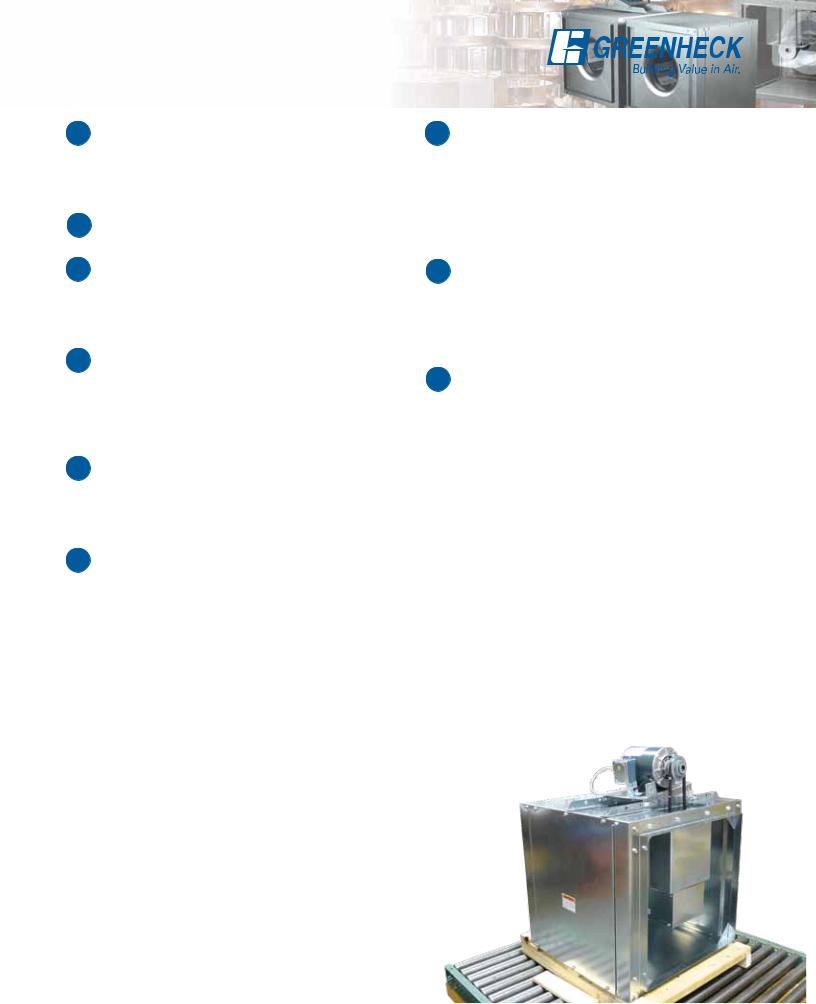
•Packaged-product is tested in accordance with ISTA (International Safe Transit Association) standards and procedures.
Turn to our inline fans to meet your requirements for applications in office buildings, schools and hospitals to name a few.
3
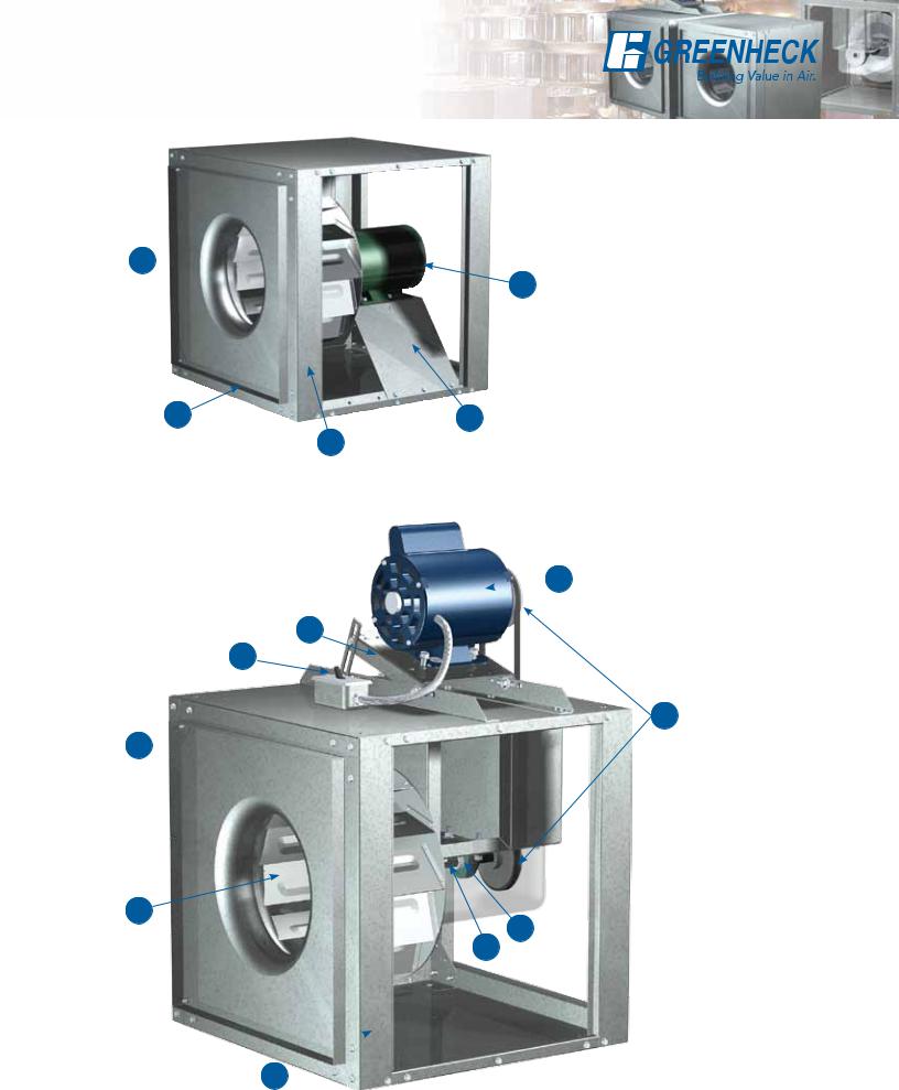
Standard Construction Features
Model SQ Direct Drive
3 
5
4 |
2 |
1
Model BSQ Belt Drive
 5
5
2
9
7
4 
3
6
8
1 
4
Standard Construction Features
1 Cabinet Construction
The fan housing is constructed of rigid structural members and formed galvanized steel panels. (Aluminum construction is optional in all SQ sizes 60 160 and in BSQ sizes 70 300).
2 Drive Frame
Constructed from heavy-gauge steel.
7 Drive Assembly
Drives are sized for a minimum of 150 percent of driven horsepower. Machined cast iron pulleys are factory set to the required RPM and adjustable for final system balancing. Belts are static free and oil resistant. Belt adjustment is accomplished by loosening fasteners, sliding the motor plate and retightening fasteners.
3 Wheel
An aluminum, backward inclined, nonoverloading centrifugal wheel is utilized to deliver maximum efficiency. Each wheel is statically and dynamically balanced.
4 Duct Collars
Inlet and discharge duct collars are provided for easy duct connection. The square design provides a larger discharge area than tubular centrifugal and vane axial fans; outlet velocities are reduced for quieter operation.
5 Motor
Permanently lubricated, sealed ball bearing motors are selected to provide years of trouble-free operation with minimal maintenance.
6 Bearings
100 percent factory tested bearings are designed specifically for air handling applications with a minimum L10 life in excess of 100,000 hours (L50 average life in excess of 500,000 hours).
8 Fan Shaft
Fan shafts are precisely sized, ground and polished so the first critical speed is at least 25 percent over the maximum operating speed.
Close tolerances where the shaft makes contact with bearings result in longer bearing life.
9 Disconnect Switch
NEMA-1 disconnect switch is factory-mounted and wiring is provided from the motor as standard. All wiring and electrical components comply with the National Electric Codes and materials are UL Listed. Other NEMA enclosure disconnect switches are optional.
Access Panels (not shown on images)
The cabinet construction features two removable access panels permitting easy access to all interior components.
5

Vari-Green® Options
Vari-Green® Motor - Model SQ
Greenheck’s electronically commutated (EC)
Vari-Green (VG) motor |
|
combines motor |
|
technology, controllability |
|
and energy-efficiency into |
|
one single low maintenance |
® |
unit and is the industry’s first
fully controllable motor. When combined with Greenheck’s SQ fans, all the CFM and static pressure ranges of a belt drive can be attained with the benefits of a direct drive.
The Vari-Green motor is available in:
•1/6 - 3/4 horsepower 115 volt only.
•1 horsepower 115/208-230 volt.
•2 horsepower 208-230 volt.
All motors are available in a 50/60 Hz power.
Benefits
Operates on AC power that’s converted to DC— providing a more efficient motor operation as compared to an AC operation.
•The motor can attain up to 85% efficiency and reduce energy consumption.
•Watt savings of 30-70% depending on RPM. Note: As motor speed is turned down, efficiency stays high as compared to an AC motor that decreases dramatically.
•Operates cooler than a standard AC motor at lower RPMs. A cooler motor has longer motor life and reduces energy consumption.
•80% usable RPM turndown vs. 30%. (chart at right)
•SQ fans with Vari-Green motors can provide all the CFM and static pressure ranges of a comparable belt drive.
•Maintenance costs are reduced as there are no belts or bearings to replace and no pulleys to adjust.
•Direct drive fans are often preferred where maintenance access is difficult.
•The Vari-Green provides a solution for demand controlled ventilation applications.
Vari-Green Advantages
•Initial cost is similar to a belt drive
•Lower operating cost
•No maintenance, no belts, pulleys or bearings
•Easy RPM adjustment
Features
1.Dial on Motor Control - A potentiometer (dial on motor control) is mounted on the motor for easy speed adjustment for system balance. Simply turn the dial there are no belts and pulleys to adjust.
2.Control Wire Inputs - the motor 0-10V DC signal from Building Systems, Vari-Green Controls controls to adjust motor speed
1 |
2 |
|
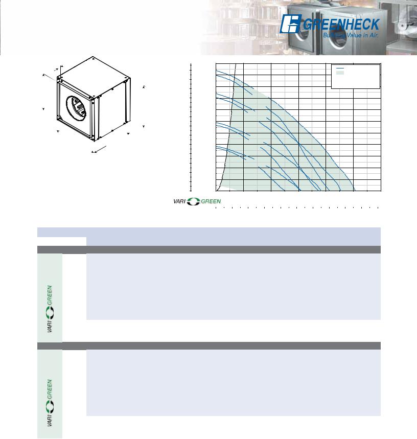
Comparisons: Belt, Direct Drive with PSC and Direct Drive with Vari-Green
Motor Turndown Comparison
|
600 |
|
|
|
50% |
|
|
|
75% |
100% |
|
|
|
|
|
|
|
|
|
|
|
|
500 |
|
|
|
|
|
SQ-120 |
|
|
|
|
|
|
|
|
|
|
|
|
|
|
(WATTS) |
400 |
|
|
|
|
|
with PSC |
|
||
|
|
|
|
|
|
|
|
|||
|
|
|
|
|
||||||
300 |
|
|
|
Not recommended |
Energy Savings |
|
||||
POWER |
|
|
|
|
BSQ-120 |
|
|
|
|
|
200 |
|
|
|
Single Phase* |
|
|
|
|||
INPUT |
|
|
|
|
|
|
|
|
|
|
100 |
|
|
|
|
|
|
SQ-120 with |
|
||
|
|
|
|
|
|
|
||||
|
|
|
|
|
|
|
|
|
|
|
|
0 |
|
|
|
|
|
|
|
|
|
|
|
|
|
|
|
|
|
|||
|
0 |
350 |
|
|
FAN SPEED (RPM) |
|
|
|
1750 |
|
* BSQ is a belt driven fan
The length of each curve indicates the practical turndown range. Data is for 1/2 hp motors with load of 0.35 Bhp at full speed
Constant Volume Life Cycle Analysis
Three Year Cost Comparison
$2,500
2,250
2,000
1,750
1,500
1,250
1000
750
500
250
$0
BSQ- |
SQ- |
SQ- |
120 |
120-A5 |
120-VG |
 Initial Cost
 Maintenance cost over three years
  Operating cost over three years
Analysis is based on operating costs for a period of three years where the fans
operate continuously at 1725 rpm, 24/7, with an energy
rate of $0.10/kWh. Maintenance on the SQ-120 is estimated at $65/yr.
Note: Example is based on a relative cost. Use and installation variables may produce different results.
6

Vari-Green® Options
Demand Control Ventilation for
Multistory Buildings
Applications requiring constant pressure or variable volume can utilize SQ fans with Vari-Green motors
and Vari-Green controls. |
|
|
|
|
|
|
Demand control |
|
|||||
Variable Volume |
||||||
ventilation systems |
Operating Cost Analysis |
|||||
reduce the amount |
|
Variable Volume vs. Constant Volume |
||||
|
$2,000 |
|
|
|
||
|
|
|
||||
of energy used by |
|
|
|
|||
|
1,750 |
|
|
|
||
decreasing the speed of |
|
|
|
|||
1,500 |
|
|
|
|||
the fan when demand |
|
|
|
|||
|
1,250 |
|
|
|
||
is low. This in turn |
|
|
|
|
||
|
|
|
|
|
||
lessens the amount |
|
1000 |
|
|
|
|
|
|
|
|
|
||
of conditioned air |
|
750 |
|
|
|
|
exhausted and further |
|
500 |
|
|
|
|
reduces total operating |
|
250 |
|
|
|
|
costs associated with |
|
$0 |
|
|
|
|
air conditioning and |
|
|
Variable |
Constant |
||
heating in multistoried |
|
|
Volume |
Volume |
||
|
Heating Cost |
|
|
|||
buildings such as: hotels, |
|
|
|
|||
|
Cooling Cost |
|
|
|||
multifamily complexes, |
|
|
|
|||
|
Fan Operating Cost |
|
|
|||
institutional facilities, |
Example of potential savings |
|||||
and high rise commercial |
||||||
based on a northeast city in |
||||||
buildings. |
the USA using Vari-Green |
|||||
components for variable volume.
Vari-Green® Controls
Transformer - Provides 24V power from the existing line voltage at the fan to the Vari-Green motor and controls. Dual voltage primary (120/240V) transformer provided with the fan.
Remote Dial - Allows for remote, manual airflow adjustments. Wall plate with dial may be mounted in a standard 2x4 inch electrical junction box.
Two Speed Control with Integral Transformer
Control allows motor rpm to be set at two independent speeds (high or low). Meets minimum airflow requirements with the ability to bump up to high speed in emergency or meet maximum airflow requirements, or reset down to low for energy conservation.
Constant Pressure Control-Indoor - Control VariGreen motor via static (variable volume) or velocity (constant CFM) pressure on the inlet or outlet side of the fan. Optional, one or two, duct or room probes for use in:
•Multifamily structures - Apartments, condos, hotels; dryers, residential kitchens and bathrooms.
•Institutional facilities - Schools, prisons, multistory office buildings; bathrooms.
The Vari-Green constant pressure control is preprogramed and easy to install for applications that include: venting dryers, bathrooms, residential type kitchen space or industrial process exhaust.
Contact fans@greenheck.com for more information.
Daily Operating Comparison: Variable Volume and Constant Volume
|
|
|
|
|
|
|
|
Hypothetical (Hotel Bathroom) |
|
|
|
|
|
|
|
|
|||||||||||
Operation |
|
|
|
|
|
|
Variable Volume - Load Shape |
|
|
|
|
|
|
|
|
||||||||||||
10080$$$$$$$$$$$$$$$$$$$$$$$$ |
|||||||||||||||||||||||||||
|
|||||||||||||||||||||||||||
|
60$$$$$$$$$$$$$$$$$$$$$$$$ |
||||||||||||||||||||||||||
|
40$$$$$$$$$$$$$$$$$$$$$$$$ |
||||||||||||||||||||||||||
|
20$$$$$$$$$$$$$$$$$$$$$$$$ |
||||||||||||||||||||||||||
of |
$$$$$$$$$$$$$$$$$$$$$$$$ |
||||||||||||||||||||||||||
|
|
|
|
||||||||||||||||||||||||
% |
0% |
1 |
2 |
3 |
4 |
5 |
6 |
7 |
8 |
9 |
10 |
11 |
12 |
13 |
14 |
15 |
16 |
17 |
18 |
19 |
20 |
21 |
22 |
23 |
24 |
||
|
|
|
|
|
|
|
|
|
|
|
|
|
|
|
|
|
|
|
|
|
|
|
|
|
|
||
|
|
|
|
|
|
|
|
Time of Day |
|
|
|
|
|
|
|
|
|
|
|
|
|||||||
|
|
|
Series 1 |
|
|
|
|
|
|
|
|
|
|
|
|
|
|
|
|
||||||||
Demand controlled ventilation offers significant energy savings by exhausting only the necessary amount of air throughout the day.
Operation |
|
|
|
|
|
|
|
Constant Volume - Load Shape |
|
|
|
|
|
|
|
|
|
|
|
|||||||||||||||||||
100 |
|
|
|
|
|
|
|
|
|
|
|
|
|
|
|
|
|
|
|
|
|
|
|
|
|
|
|
|
|
|
|
|
|
|
|
|
|
|
|
80 |
|
|
|
|
|
|
|
|
|
|
|
|
|
|
|
|
|
|
|
|
|
|
|
|
|
|
|
|
|
|
|
|
|
|
|
|
|
|
|
|
|
|
|
|
|
|
|
|
|
|
|
|
|
|
|
|
|
|
|
|
|
|
|
|
|
|
|
|
|
|
|
|
|
|
|
|
|
60 |
|
|
|
|
|
|
|
|
|
|
|
|
|
|
|
|
|
|
|
|
|
|
|
|
|
|
|
|
|
|
|
|
|
|
|
|
|
|
|
|
|
|
|
|
|
|
|
|
|
|
|
|
|
|
|
|
|
|
|
|
|
|
|
|
|
|
|
|
|
|
|
|
|
|
|
|
|
40 |
|
|
|
|
|
|
|
|
|
|
|
|
|
|
|
|
|
|
|
|
|
|
|
|
|
|
|
|
|
|
|
|
|
|
|
|
|
|
|
|
|
|
|
|
|
|
|
|
|
|
|
|
|
|
|
|
|
|
|
|
|
|
|
|
|
|
|
|
|
|
|
|
|
|
|
|
of |
20 |
|
|
|
|
|
|
|
|
|
|
|
|
|
|
|
|
|
|
|
|
|
|
|
|
|
|
|
|
|
|
|
|
|
|
|
|
|
|
|
|
|
|
|
|
|
|
|
|
|
|
|
|
|
|
|
|
|
|
|
|
|
|
|
|
|
|
|
|
|
|
|
|
|
|
||
0% |
|
|
|
|
|
|
|
|
|
|
|
|
|
|
|
|
|
|
|
|
|
|
|
|
|
|
|
|
|
|
|
|
|
|
|
|
|
|
% |
1 |
2 |
3 |
4 |
5 |
6 |
7 |
8 |
9 |
10 |
11 |
12 |
13 |
14 |
15 |
16 |
17 |
18 |
19 |
20 |
21 |
22 |
23 |
24 |
||||||||||||||
|
|
|
|
|
|
|
|
|
|
|
|
|
|
|
|
|
|
|
|
|
|
|
|
|
|
|
|
|
|
|
|
|
|
|
|
|
|
|
|
|
|
|
|
|
|
|
|
Time of Day |
|
|
|
|
|
|
|
|
|
|
|
|
|
|
|
|
|
|
|
||||||||||
|
|
|
Series 2 |
|
|
|
|
|
|
|
|
|
|
|
|
|
|
|
|
|
|
|
|
|
|
|
|
|||||||||||
Note: A standard VFD compatible motor can also function within a variable volume system.
Constant Pressure Control-Outdoor
(previously referred to as GreenVent)
Control Vari-Green motor via static pressure on the inlet side of the fan. Includes one duct probe and transducer for use in:
•Multifamily structures - Apartments, condos, hotels; residential kitchen, dryer facilities and bathrooms.
•Institutional facilities - Schools, prisons, multistory.
Air Quality – VOC - Control a Vari-Green motor via changes in volatile organic compounds (VOC’s). VOC’s are gasses that are emitted from humans, building materials, perfumes, foods, and furniture off-gassing. Range is 0-2000 CO2 ppm equivalent.
•Institutional facilities – Schools, court house, hospitals; bathrooms, waiting rooms, cafeteria.
•Commercial buildings – Office space, conference rooms, bathrooms, break room.
Air Quality – Temperature and Humidity - Control Vari-Green motor via changes in temperature, humidity, or both. Range is 32 to 120°F and 0 to 100% relative humidity.
•Multifamily structures – Apartments, condos, hotels; bathrooms, utility rooms.
•Commercial buildings – Office buildings; office
space, conference rooms, utility rooms, bathrooms.
7

Options and Accessories
Aluminum Construction
Aluminum construction is available for all direct drive sizes 60-160 and belt drive sizes 70-300. Some drive frame components may still be of galvanized construction to maintain structural integrity.
Speed Controllers
Available for use with shaded pole and permanent split capacitor (PSC) motors on model SQ fans. They provide an economical means of system balancing with direct drive fans.
Inlet and Outlet Guards
Inlet and outlet guards provide protection for nonducted applications. Guards are fabricated of welded wire on a galvanized steel frame. They are easily removed for maintenance and inspection.
Belt Drive Motor Cover and Belt Guard
For belt driven fans, combination motor cover and belt guards constructed of galvanized steel are available for protection of motors, drives and personnel. Standard on units specified with UL.
Direct Drive Motor Cover
Formed, galvanized steel motor covers are available to isolate direct drive motors from the airstream. When motor covers are furnished, vents to the exterior of the fan are provided to ensure sufficient motor cooling.
Backdraft Dampers
Gravity or motorized parallel blade dampers (model WD-330) are available for duct mounting. These dampers feature sturdy galvanized frames, aluminum blades with vinyl blade seals, and a balanced design for minimal resistance to airflow.
Control Dampers
Square, opposed blade volume control dampers (model VCD) are available for duct mounting. These dampers feature sturdy galvanized frames, and steel blades with optional blade and jamb seals.
A balanced design results in minimal resistance to airflow.
Coatings
Wide variety of coatings and colors are available.
Decorative coatings are available in sixteen standard colors.
Protective coatings are available in a choice of five electrostatic applied powders providing an available selection for most environments.
All Greenheck coatings
and resistance charts can be found in our Performance Coatings for Commercial & Industrial Fans brochure.
Inlet Vane Dampers
Variable inlet vane dampers (model IVDE) are available for models SQ and BSQ sizes 140-420 and are factory-assembled to the fan. They can be specified for either manual or automatic operation (controls furnished by others). These dampers are
constructed of heavy-gauge steel and feature uniform blade movement for positive control. Companion inlet rings for round duct connections are also available.
Insulated Housing
For noise reduction and condensation control, the interior of the fan housing can be lined with a 1-inch fiberglass duct liner. The optional motor cover can also be insulated.
The table depicts the radiated sound reduction that can be obtained in each octave band for the insulated housing and motor cover together.
Approximate Radiated Sound Attenuation (dB)
Octave Band |
1 |
2 |
3 |
4 |
5 |
6 |
7 |
8 |
|
|
|
|
|
|
|
|
|
Sizes 60 - 130 |
-2 |
-7 |
-4 |
-4 |
-6 |
-13 |
-13 |
-9 |
|
|
|
|
|
|
|
|
|
Sizes 140 - 420 |
-3 |
-2 |
-5 |
-4 |
-5 |
-5 |
-7 |
-8 |
|
|
|
|
|
|
|
|
|
Wiring Pigtail
Allows direct hook-up to the power supply eliminating field wiring at the fan.
8
Filter Options
The filter box is designed to provide a compact and convenient clean air solution. Factory-assembled as a single unit, this fan eliminates the costly process of designing, fabricating and installing special remote filter box assemblies. Both the fan and filter section feature removable access panels on both sides to remove and replace filters, making fan maintenance simple and fast.
Model Selection Procedure
1.Calculate system pressure drop and cfm requirements (not including filters).
2.Make a preliminary model size selection.
3.Calculate a filter pressure drop (P) for the preliminary
model size selected in step 2 using the equation: P = F x ( 10,000cfm )2
• To determine the filter factor (F) refer to chart below.
4.Add the filter pressure drop (P) to the system pressure drop and make a revised model size selection.
Model SQ Model
Model BSQ
Fan |
Filter Box |
|
Filter |
|
|
Filter Factor (F) |
|
|
|
Filter Size |
|
1 inch (25) |
|
2 inch (51) |
|||||
Size |
Weight |
|
Quantity |
|
|
|
|
|
|
|
Aluminum |
|
Paper Filters (MERV 7) |
Aluminum |
|
Paper Filters (MERV 8) |
|||
|
|
|
|
|
|
||||
60 - 75 |
40 |
10 x 12 |
1 |
186 |
|
318.06 |
251.1 |
|
303.18 |
(18) |
(254 x 305) |
|
|
||||||
|
|
|
|
|
|
|
|
||
80 - 95 |
74 |
14 x 25 |
1 |
21.8 |
|
37.28 |
29.43 |
|
35.53 |
(34) |
(356 x 635) |
|
|
||||||
|
|
|
|
|
|
|
|
||
100 |
88 |
16 x 20 |
2 |
8.72 |
|
14.91 |
11.77 |
|
14.21 |
(40) |
(406 x 508) |
|
|
||||||
|
|
|
|
|
|
|
|
||
120 |
114 |
16 x 25 |
2 |
5.58 |
|
9.54 |
7.53 |
|
9.10 |
(52) |
(406 x 635) |
|
|
||||||
|
|
|
|
|
|
|
|
||
130 |
120 |
20 x 20 |
2 |
5.58 |
|
9.54 |
7.53 |
|
9.10 |
(54) |
(508 x 508) |
|
|
||||||
|
|
|
|
|
|
|
|
||
140 |
174 |
20 x 25 |
2 |
3.57 |
|
6.11 |
4.82 |
|
5.82 |
(79) |
(508 x 635) |
|
|
||||||
|
|
|
|
|
|
|
|
||
160 |
246 |
20 x 20 |
4 |
2.09 |
|
3.57 |
2.82 |
|
3.41 |
(112) |
(508 x 508) |
|
|
||||||
|
|
|
|
|
|
|
|
||
70 - 80 - 90 |
117 |
14 x 25 |
1 |
21.8 |
|
37.28 |
29.43 |
|
35.53 |
(53) |
(356 x 635) |
|
|
||||||
|
|
|
|
|
|
|
|
||
100 |
120 |
16 x 20 |
2 |
8.72 |
|
14.91 |
11.77 |
|
14.21 |
(54) |
(406 x 508) |
|
|
||||||
|
|
|
|
|
|
|
|
||
120 |
144 |
16 x 25 |
2 |
5.58 |
|
9.54 |
7.53 |
|
9.10 |
(79) |
(406 x 635) |
|
|
||||||
|
|
|
|
|
|
|
|
||
130 - 130HP |
140 |
20 x 20 |
2 |
5.58 |
|
9.54 |
7.53 |
|
9.10 |
(64) |
(508 x 508) |
|
|
||||||
|
|
|
|
|
|
|
|
||
140 - 140HP |
181 |
20 x 25 |
2 |
3.57 |
|
6.11 |
4.82 |
|
5.82 |
(82) |
(508 x 635) |
|
|
||||||
|
|
|
|
|
|
|
|
||
160 - 160HP |
294 |
20 x 20 |
4 |
2.09 |
|
3.57 |
2.82 |
|
3.41 |
(133) |
(508 x 508) |
|
|
||||||
|
|
|
|
|
|
|
|
||
180 - 180HP |
344 |
20 x 25 |
4 |
1.34 |
|
2.29 |
1.81 |
|
2.18 |
(156) |
(508 x 635) |
|
|
||||||
|
|
|
|
|
|
|
|
||
|
|
12 x 25 |
3 |
|
|
|
|
|
|
200 - 200HP |
441 |
(305 x 635) |
0.77 |
|
1.32 |
1.04 |
|
1.26 |
|
|
|
|
|||||||
(200) |
16 x 25 |
3 |
|
|
|||||
|
|
|
|
|
|
|
|||
|
|
(406 x 635) |
|
|
|
|
|
|
|
|
|
|
|
|
|
|
|
|
|
|
|
20 x 25 |
4 |
|
|
|
|
|
|
240 - 240HP |
573 |
(508 x 635) |
0.41 |
|
0.70 |
0.55 |
|
0.67 |
|
|
|
|
|||||||
(260) |
16 x 25 |
4 |
|
|
|||||
|
|
|
|
|
|
|
|||
|
|
(406 x 635) |
|
|
|
|
|
|
|
|
|
|
|
|
|
|
|
|
|
300 - 300HP |
759 |
20 x 25 |
8 |
0.33 |
|
0.56 |
0.45 |
|
0.54 |
(344) |
(508 x 635) |
|
|
||||||
|
|
|
|
|
|
|
|
||
|
|
16 x 25 |
10 |
|
|
|
|
|
|
360 - 360HP |
957 |
(406 x 635) |
0.15 |
|
0.26 |
0.20 |
|
0.25 |
|
|
|
|
|||||||
(434) |
20 x 25 |
5 |
|
|
|||||
|
|
|
|
|
|
|
|||
|
|
(508 x 635) |
|
|
|
|
|
|
|
|
|
|
|
|
|
|
|
|
|
|
|
16 x 25 |
5 |
|
|
|
|
|
|
420 |
1185 |
(406 x 635) |
0.13 |
|
0.22 |
0.18 |
|
0.21 |
|
|
|
|
|||||||
(538) |
20 x 25 |
10 |
|
|
|||||
|
|
|
|
|
|
|
|||
|
|
(508 x 635) |
|
|
|
|
|
|
|
|
|
|
|
|
|
|
|
|
|
Note: 24-inch side clearance is recommended for accessing and removing filters. All dimensions in inches (millimeters) and weight in pounds (kilograms).
9
Discharge Configurations
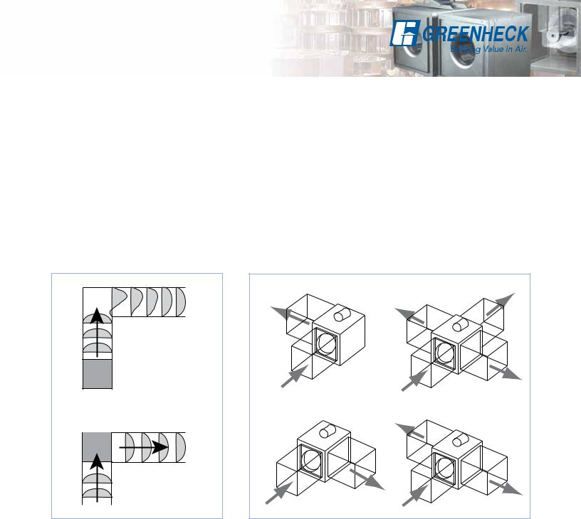
The side discharge option helps to reduce system effect. It will increase performance and reduce installation labor. The most notable is reducing system effects. Note: The figure 1 example shows the air being discharged into the corner. It will take several duct lengths before the airflow becomes laminar or smooth again after making the turn.
In figure 2, the fan is placed in the corner using a side discharge. In this configuration the air flow pattern at discharge is smooth and supports a more predictable system. Remember the duct length on the discharge side, should be approximately two to three wheel diameters to achieve catalog performance.
Discharge Configuration
Fan performance will change with different discharge positions. Catalog data is based on an inline discharge. Right side discharge will give you 108% of cataloged performance and left side will give you 109% of cataloged performance. Use figure 3 to locate the orientation to fit your application. Figures 4 and 5 on page 11 illustrate the proper side discharge definitions. Refer to Greenheck’s CAPS (Computer Aided Product Selection) program or consult factory for performance modifications.
Fan
Figure 1
Fan |
Figure 2
Left Discharge |
Left, Right & Inline Discharge |
Right Discharge |
Left & Right Discharge |
Figure 3
10
Side Discharge
SQ Side Discharge |
BSQ Side Discharge |
Left Side |
Access Door |
Discharge |
Inline |
|
Discharge |
Figure 4
|
Height |
Inlet |
|
Width |
Right Side |
|
Discharge |
SQ Side Discharge Duct Openings
Unit Size |
Width |
Height |
||
|
|
|
||
60-75 |
97⁄8 (251) |
87⁄8 (225) |
||
80-95 |
127⁄8 (327) |
117⁄8 (302) |
||
100 |
137⁄8 (352) |
137⁄8 (352) |
||
120 |
157⁄8 |
(403) |
157⁄8 |
(403) |
130 |
177⁄8 |
(454) |
177⁄8 |
(454) |
140 |
197⁄8 |
(505) |
197⁄8 |
(505) |
160 |
227⁄8 |
(581) |
227⁄8 |
(581) |
All dimensions in inches (millimeters).
Left Side |
|
Discharge |
Access Door |
|
Inline |
|
Discharge |
Figure 5
Height
Inlet
Width |
Right Side |
|
Discharge |
BSQ Side Discharge Duct Openings
Unit Size |
Width |
Height |
|
|
|
|
|
70-80-90 |
117⁄8 (302) |
117⁄8 (302) |
|
100 |
137⁄8 (352) |
137⁄8 (352) |
|
120 |
157⁄8 (403) |
157⁄8 (403) |
|
130-130HP |
177⁄8 (454) |
177⁄8 (454) |
|
140-140HP |
197⁄8 (505) |
197⁄8 (505) |
|
160-160HP |
227⁄8 (581) |
227⁄8 (581) |
|
180-180HP |
237⁄8 (606) |
237⁄8 (606) |
|
200-200HP |
277⁄8 (708) |
277⁄8 (708) |
|
240-240HP |
287⁄8 |
(733) |
347⁄8 (886) |
300-300HP |
317⁄8 |
(810) |
417⁄8 (1064) |
360-360HP |
327⁄8 |
(835) |
377⁄8 (962) |
420 |
347⁄8 |
(886) |
437⁄8 (1114) |
All dimensions in inches (millimeters).
11

Horizontal and Vertical
Mounting Options
All SQ and BSQ fan models can be mounted horizontally, vertically or at an angle. For ease of installation, knockouts are provided at each location where mounting brackets are shown in figures 6, 7 and 8. Optional brackets are universally adjustable to mount in any of these locations.
|
NOTE: Hanging |
|
|
G |
|
A |
rails by others |
E |
A |
||
BG |
B |
||||
|
|
|
|||
|
F |
|
|
||
|
|
|
|
B |
|
A |
A |
|
|
|
F |
E |
|
B |
|
Figure 6
Horizontal Hanging or Base Mount
With either a hanging or base mount the motor may be located on either side. The base mount allows top access panels only.
|
|
E |
A |
C |
|
|
|
||
A |
|
E |
|
|
C |
F |
|
|
|
|
|
|
||
|
|
|
|
A

C |
A |
F E |
|
A |
|
|
|
C |
Figure 7
Horizontal Hanging or Base Mount
With a hanging mount, the motor may be located on either top or bottom. The base mount allows
top motor location only. Both options provide access panels on two sides.
|
|
D |
|
NOTE: Hanging |
B G |
D |
rails by others |
|
B G |
|
|
|
|
|
|
|
Figure 8 |
|
|
|
|
|
|
|
|
Vertical Hanging or Base Mount |
|
|
|
|
|
||
|
|
Mounting brackets are turned |
|
|
|
|
|
||
|
|
90 degrees for vertical mounting. |
B |
D |
|
|
|
||
|
|
Access panels are located on the |
|
|
|
|
|||
|
|
|
|
|
B |
|
|||
|
|
two sides adjacent to the motor. |
|
|
|
D |
|||
|
|
|
|
|
|
||||
Model |
A |
B |
C |
|
D |
E |
F |
|
G |
SQ 60-75 |
105⁄8 (270) |
17 (432) |
153⁄4 (400) |
|
87⁄8 (225) |
193⁄4 (502) |
7 (178) |
|
|
SQ 80-95 |
131⁄4 (337) |
20 (508) |
183⁄4 (476) |
117⁄8 (302) |
43 (1092) |
273⁄8 (695) |
|
Hanging |
|
BSQ 70-90 |
185⁄8 (473) |
201⁄8 (511) |
183⁄4 (476) |
117⁄8 (302) |
485⁄16 (1227) |
273⁄8 (695) |
|
||
|
rails not |
||||||||
SQ-BSQ 100 |
185⁄8 (473) |
221⁄8 (562) |
203⁄4 (527) |
137⁄8 (352) |
447⁄8 (1140) |
24 (610) |
|
included. |
|
SQ-BSQ 120 |
185⁄8 (473) |
24 (610) |
223⁄4 (578) |
|
16 (406) |
493⁄8 (1254) |
281⁄8 (714) |
|
Supplied by |
SQ-BSQ 130 |
185⁄8 (473) |
261⁄8 (664) |
243⁄4 (629) |
177⁄8 (454) |
44 (1118) |
23 (584) |
|
others. |
|
|
|
||||||||
SQ-BSQ 140 |
195⁄8 (498) |
281⁄8 (714) |
263⁄4 (679) |
197⁄8 (505) |
501⁄16 (1272) |
28 (711) |
|
|
|
SQ-BSQ 160 |
231⁄2 (597) |
31 (787) |
293⁄4 (756) |
227⁄8 (581) |
495⁄8 (1260) |
235⁄8 (600) |
|
|
|
BSQ 180 |
251⁄2 (648) |
331⁄2 (851) |
299⁄16 (751) |
223⁄4 (578) |
529⁄16 (1335) |
241⁄2 (622) |
|
Hanging |
|
BSQ 200 |
291⁄8 (740) |
37 (940) |
333⁄4 (857) |
263⁄4 (679) |
643⁄16 (1630) |
321⁄4 (819) |
|
||
|
rails not |
||||||||
BSQ 240 |
315⁄8 (803) |
441⁄4 (1124) |
403⁄4 (1035) |
337⁄8 (860) |
661⁄2 (1689) |
321⁄8 (816) |
|
included. |
|
BSQ 300 |
35 (889) |
51 (1295) |
473⁄4 (1213) |
407⁄8 (1038) |
691⁄8 (1756) |
313⁄8 (797) |
|
Supplied by |
|
BSQ 360 |
383⁄4 (974) |
571⁄4 (1454) |
531⁄2 (1359) |
463⁄4 (1187) |
76 (1930) |
3411⁄16 (881) |
|
others. |
|
|
|
||||||||
BSQ 420 |
471⁄8 (1197) |
63 (1600) |
597⁄8 (1521) |
597⁄8 (1521) |
901⁄2 (2299) |
401⁄2 (1029) |
|
|
|
All dimensions in inches (millimeters).
12
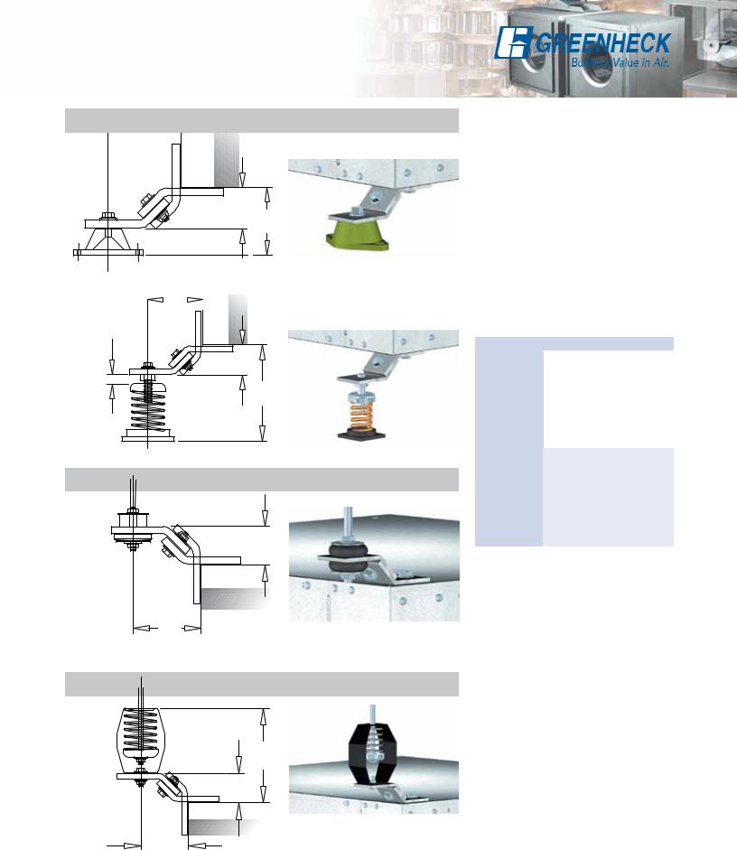
Base Mount or Hanging Isolators
j |
Standing Neoprene Isolator |
|
h
L
j |
Standing Spring Isolator |
|
|
5⁄8 inch (16 mm) nominal
h
i
Hanging Neoprene Isolator
h
j
Hanging Spring Isolator
K
h
j |
Complete isolation kits are available with either neoprene or spring isolators and are sized to match the weight of the specified fan
size. The base isolator support brackets are designed to permit mounting of the fan with the motor located on top or either side. The hanging isolator support brackets are designed to permit mounting of the fan with the motor located on top, bottom or side.
Note: Hanging rods to be supplied by others.
Model |
H |
I |
J |
K |
L |
|
SQ 60-75 |
|
|
|
|
|
|
SQ 80-95 |
|
|
|
|
|
|
|
|
|
|
|
|
|
BSQ 70-90 |
13⁄8 |
51⁄2 |
2 |
63⁄4 |
25⁄16 |
|
SQ-BSQ 100 |
||||||
(35) |
(140) |
(51) |
(171) |
(59) |
||
|
||||||
SQ-BSQ 120 |
||||||
|
|
|
|
|
||
SQ-BSQ 130 |
|
|
|
|
|
|
|
|
|
|
|
|
|
SQ-BSQ 140 |
|
|
|
|
|
|
SQ-BSQ 160 |
|
|
|
|
|
|
|
|
|
|
|
|
|
BSQ 180 |
|
|
|
|
|
|
BSQ 200 |
13⁄8 |
51⁄2 |
2 |
63⁄4 |
25⁄8 |
|
|
||||||
BSQ 240 |
||||||
(35) |
(140) |
(51) |
(171) |
(67) |
||
BSQ 300 |
||||||
|
|
|
|
|
||
|
|
|
|
|
|
|
BSQ 360 |
|
|
|
|
|
|
BSQ 420 |
|
|
|
|
|
|
|
|
|
|
|
|
All dimensions in inches (millimeters).
13
Typical Installation
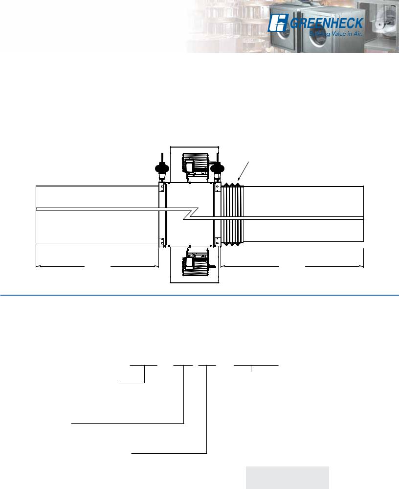
Models SQ and BSQ ducted inline fans are designed for the exhaust, supply or recirculation of air in a building. Typical installation requires ductwork on the inlet and outlet side of the fan. A minimum of three duct diameters is required on the inlet and outlet of the fan to minimize system effect losses. See the diagram below for a typical installation.
Installations can include flexible duct connections (by others) on either the inlet or outlet side of the fan or
both. The motor is rigidly mounted and can be oriented in any direction (top, bottom, side).
The model BSQ ducted inline fan must be installed with the motor accessible for maintenance and inspection.
External isolators are recommended, hanging (shown below) or base mounted.
Installation must meet all local governing codes and the NEC.
Flexible duct (by others)
3 Wheel
Diameters
3 Wheel
Diameters
Model Number Code
The model number system is designed to completely identify the fan. The correct code letters must be specified to designate belt or direct drive. The remainder of the model number is determined by the size and performance selected from the following pages.
BSQ - 120 HP - VG/75/A
Model Configuration
Bsq - Belt Drive Inline Exhaust
SQ - Direct Drive Inline Exhaust
Fan Size
60 through 420
Pressure Level (Belt Drive Only)
HP - High Pressure Wheel
VG = Vari-Green®
(Direct Drive only) |
|
|
||
Motor HP (Belt Drive only) |
|
|||
6 = 1/6 |
7 |
= 3/4 |
30 = |
3 |
4 = 1/4 |
10 |
= 1 |
50 = |
5 |
3 = 1/3 |
15 |
= 11⁄2 |
75 = |
71⁄2 |
5 = 1/2 |
20 |
= 2 |
100 = |
10 |
Motor RPM (Direct Drive only) |
|
|||
A = 1725 |
D = 1550 |
|
||
B = 1140 |
E = 1050 |
|
||
C = 860 |
G = 1300 |
|
||
International
(See CAPS for performance)
K = 950 RPM J = 1475 RPM
14
SQ 60-65 - Direct Drive
1
(25)
87⁄8
(225)
 12
12  13
13
(305) |
(330) |
Damper size = 9 x 9 (229 x 229) Unit weight** = 26 (12) Housing thickness = 18 ga Outlet velocity = 1.828 x cfm
12
(305) (Pa) PressureStatic
|
|
0.55 |
|
|
|
|
|
|
|
|
|
|
|
|
|
130 |
|
|
|
|
|
|
|
|
|
|
|
|
RPM (Direct) |
|
|
|
|
|
|
|
|
|
|
|
|
|
|
RPM (Vari Green) |
|
||
|
|
0.50 |
|
|
|
|
|
|
|
|
|
|
|
||
120 |
|
E |
|
|
|
|
|
|
|
|
|
Density 0.075 lb/ft 3 |
|
||
|
|
|
|
|
|
|
|
|
|
|
|
||||
|
|
|
V |
|
|
|
|
|
|
|
|
|
Density 1.2 kg/m |
3 |
|
|
|
0.45 |
R |
|
|
|
|
|
|
|
|
|
|
|
|
110 |
|
U |
|
065 |
|
|
|
|
|
|
|
||||
|
|
C |
|
|
|
|
|
|
|
|
|||||
|
|
|
|
|
|
- |
|
|
|
|
|
||||
|
|
|
E |
|
|
|
|
|
|
|
|
|
|||
|
|
|
|
|
|
|
|
VG |
|
|
|
|
|
||
100 |
|
|
M |
060 |
|
|
|
|
|
|
|
|
|||
|
0.40 |
T |
|
|
|
|
|
|
|
|
|||||
|
|
|
S |
|
|
|
- |
|
|
|
|
|
|
||
|
wg) |
|
Y |
|
|
|
VG |
|
|
|
|
|
|||
|
0.35 |
I |
|
|
|
|
|
|
|
|
|
|
|
|
|
90 |
|
|
S |
|
|
|
|
|
|
|
|
|
|
|
|
|
|
S |
|
065 |
|
|
|
|
|
|
|||||
|
|
|
060 |
|
|
|
|
|
|
||||||
80 |
(in. |
|
H |
D |
|
|
|
|
|
||||||
|
|
T |
|
- |
|
|
- |
|
|
|
|
|
|||
|
|
F |
|
|
|
|
|
|
|
|
|
|
|||
|
Pressure |
0.30 |
O |
|
D |
|
|
|
|
|
|
|
|
||
70 |
|
O |
060 |
|
|
G |
|
|
|
|
|
|
|||
|
|
|
T |
|
|
|
|
|
|
|
|
|
|
|
|
|
|
|
F |
|
|
|
|
|
|
|
|
|
|
|
|
|
|
|
E |
|
|
|
|
|
|
|
|
|
|
|
|
|
|
0.25 |
L |
065- |
|
|
|
|
|
|
|
||||
60 |
|
E |
|
|
|
|
|
|
|
||||||
|
|
|
|
|
|
|
|
|
|||||||
|
|
|
H |
|
|
|
|
|
|
|
|
|
|
|
|
|
|
|
T |
|
- |
|
|
|
|
|
|
|
|
|
|
50 |
|
0.20 |
T |
|
|
|
|
|
|
|
|
|
|
||
|
Static |
0.15 |
|
|
G |
|
|
|
|
|
|
|
|||
|
L |
|
|
|
|
|
|
|
|
|
|
|
|
||
|
|
|
T |
|
|
|
|
|
|
|
|
|
|
|
|
40 |
|
|
C |
|
|
|
|
|
|
|
|
|
|
|
|
|
|
E |
|
065 |
|
|
|
|
|
|
|||||
|
|
|
S |
|
|
|
|
|
|
|
|||||
30 |
|
|
E |
060 |
|
|
|
|
- |
|
|
|
|
|
|
|
|
T |
|
|
|
|
|
|
|
|
|
||||
|
|
|
- |
|
|
|
|
E |
|
|
|
|
|
||
|
|
0.10 |
O |
|
E |
|
|
|
|
|
|
|
|
|
|
20 |
|
|
N |
|
|
|
|
|
|
|
|
|
|
|
|
|
|
O |
|
|
|
|
|
|
|
|
|
|
|
|
|
|
|
|
|
|
|
|
|
|
|
|
|
|
|
|
|
|
|
0.05 |
D |
|
|
|
|
|
|
|
|
|
|
|
|
10 |
|
|
|
|
|
|
|
|
|
|
|
|
|
|
|
|
|
|
|
|
|
|
|
|
|
|
|
|
|
|
|
0 |
|
0.00 0 |
50 |
|
|
|
|
|
|
100 |
150 |
200 |
250 |
|
300 |
|
|
|
|
|
|
|
|
|
|
|
Volume (cfm) |
|
|
|
|
Dimensions shown in inches (millimeters) and weight is |
|
|
|
|
|
|
|
|
|
|
|
|
|
|
|
||||
|
|
0 |
50 |
100 |
150 |
200 |
250 |
300 |
350 |
400 |
450 |
500 |
|||||||
shown in pounds (kilograms). |
|
|
|
|
|||||||||||||||
|
|
|
|
|
|
|
|
|
Volume (m3/hr) |
|
|
|
|
||||||
**Weight shown is largest cataloged Open Drip Proof motor. |
|
|
|
|
|
|
|
|
|
|
|
||||||||
|
|
|
|
|
|
|
|
|
|
|
|
|
|
|
|
||||
Motor HP |
Fan RPM |
|
|
|
|
CFM / Static Pressure in Inches wg |
|
|
|
|
|
||||||||
|
|
|
|
|
|
|
|
|
|
|
|
|
|
|
|
|
|
|
|
Direct |
|
0.000 |
0.050 |
0.100 |
0.125 |
|
0.150 |
0.200 |
|
|
0.250 |
0.300 |
0.350 |
0.375 |
|||||
|
|
|
|
|
|||||||||||||||
60 |
|
|
|
|
|
|
|
|
|
|
|
|
|
|
|
|
|
|
|
|
|
|
CFM |
126 |
102 |
79 |
63 |
|
42 |
|
|
|
|
|
|
|
|
|
|
VG-1/6 |
E-1/140 |
1050 |
BHP |
0.01 |
0.01 |
0.01 |
0.01 |
|
0.01 |
|
|
|
|
|
|
|
|
|
|
|
|
|
Sones |
1.7 |
1.7 |
1.7 |
1.7 |
|
1.8 |
|
|
|
|
|
|
|
|
|
|
|
|
|
CFM |
156 |
136 |
118 |
110 |
|
99 |
73 |
|
|
37 |
|
|
|
|
|
|
|
G-1/80 |
1300 |
BHP |
0.01 |
0.01 |
0.01 |
0.01 |
|
0.01 |
0.01 |
|
|
0.01 |
|
|
|
|
|
|
|
|
|
Sones |
2.9 |
2.7 |
2.7 |
2.6 |
|
2.6 |
2.5 |
|
|
2.5 |
|
|
|
|
|
|
|
|
|
CFM |
186 |
168 |
153 |
146 |
|
138 |
123 |
|
|
105 |
78 |
|
48 |
32 |
|
|
|
D-1/40 |
1550 |
BHP |
0.02 |
0.02 |
0.02 |
0.02 |
|
0.02 |
0.02 |
|
|
0.02 |
0.02 |
|
0.02 |
0.02 |
|
|
|
|
|
Sones |
4.3 |
4.1 |
3.9 |
3.9 |
|
3.9 |
3.9 |
|
|
4.0 |
4.0 |
|
4.1 |
4.1 |
|
|
|
|
|
CFM |
207 |
191 |
177 |
170 |
|
163 |
150 |
|
|
136 |
120 |
|
98 |
85 |
|
|
|
|
1725 |
BHP |
0.02 |
0.03 |
0.03 |
0.03 |
|
0.03 |
0.03 |
|
|
0.03 |
0.03 |
|
0.03 |
0.03 |
|
|
|
|
|
Sones |
5.4 |
5.2 |
5.1 |
5.0 |
|
5.0 |
5.1 |
|
|
5.1 |
5.3 |
|
5.5 |
5.6 |
|
|
65 |
|
|
|
|
|
|
|
|
|
|
|
|
|
|
|
|
|
|
|
|
|
|
CFM |
154 |
129 |
98 |
79 |
|
57 |
|
|
|
|
|
|
|
|
|
|
VG-1/6 |
E-1/100 |
1050 |
BHP |
0.01 |
0.01 |
0.01 |
0.01 |
|
0.01 |
|
|
|
|
|
|
|
|
|
|
|
|
|
Sones |
2.2 |
2.1 |
2.0 |
2.0 |
|
1.9 |
|
|
|
|
|
|
|
|
|
|
|
|
|
CFM |
191 |
172 |
150 |
137 |
|
123 |
92 |
|
|
52 |
|
|
|
|
|
|
|
G-1/50 |
1300 |
BHP |
0.01 |
0.01 |
0.02 |
0.02 |
|
0.02 |
0.02 |
|
|
0.02 |
|
|
|
|
|
|
|
|
|
Sones |
3.2 |
3.1 |
3.0 |
2.9 |
|
2.9 |
2.9 |
|
|
2.8 |
|
|
|
|
|
|
|
|
|
CFM |
228 |
213 |
194 |
185 |
|
175 |
153 |
|
|
129 |
101 |
|
66 |
46 |
|
|
|
D-1/30 |
1550 |
BHP |
0.02 |
0.02 |
0.03 |
0.03 |
|
0.03 |
0.03 |
|
|
0.03 |
0.03 |
|
0.03 |
0.02 |
|
|
|
|
|
Sones |
4.9 |
4.8 |
4.5 |
4.4 |
|
4.3 |
4.1 |
|
|
4.0 |
3.9 |
|
3.7 |
3.6 |
|
|
|
|
|
CFM |
254 |
242 |
224 |
216 |
|
207 |
190 |
|
|
170 |
148 |
|
124 |
111 |
|
|
|
|
1725 |
BHP |
0.03 |
0.03 |
0.03 |
0.04 |
|
0.04 |
0.04 |
|
|
0.04 |
0.04 |
|
0.04 |
0.04 |
|
|
|
|
|
Sones |
6.4 |
6.1 |
5.8 |
5.7 |
|
5.5 |
5.3 |
|
|
5.2 |
5.0 |
|
4.8 |
4.7 |
|
|
Performance certified is for installation type B: Free inlet, Ducted outlet. Performance ratings do not include the effects of appurtenances (accessories).
The sound ratings shown are loudness values in fan sones at 1.5 m (5 feet) in a hemispherical free field calculated per AMCA International Standard 301. Values shown are for installation type B: free inlet hemispherical sone levels.
15
 Loading...