


Part Number 462721


 DFDR-XXX, ssDFDR-XXX, FDR-XXX, and SSFDR-XXX Models
1 1⁄2 Hour Round Fire Dampers
Vertical and Horizontal Mount
Installation, Operation and Maintenance Instructions
DFDR-XXX, SSDFDR-XXX, FDR-XXX, and SSFDR-XXX Model Dampers are intended for installation in accordance with fire damper requirements established by:
National Fire Protection Association
NFPA Standards 80, 90A, & 101
BOCA National Building Codes
ICBO Uniform Building Codes IBC International Building Codes SBCCI Standard Building Codes
New York City (MEA listing #260-91-M)
“UL CLASSIFIED (see complete marking on product)” “UL CLASSIFIED to Canadian safety standards (see complete marking on product)”
UL Standard 555 (Classification #R13317)
Receiving and Handling
Upon receiving dampers, check for both obvious and hidden damage. If damage is found, record all necessary information on the bill of lading and file a claim with the final carrier. Check to be sure that all parts of the shipment, including accessories, are accounted for.
Dampers must be kept dry and clean. Indoor storage and protection from dirt, dust and the weather is highly recommended. Do not store at temperatures in excess of 100°F (37°C).
Installation supplements
Refer to the appropriate Greenheck installation supplements for special rquirements:
• Steel Deck Supplement
Safety WARNING:
Improper installation, adjustment, alteration, service or maintenance can cause property damage, injury or death. Read the installation, operating, and maintenance instructions thoroughly before installing or servicing this equipment.
Warranty
Greenheck warrants this equipment to be free from defects in material and workmanship for a period of one year from the purchase date. Any units or parts which prove to be defective during the warranty period will
be repaired or replaced at our option. Greenheck shall not be liable for damages resulting from misapplication or misuse of its products. Greenheck will not be responsible for any installation or removal costs. Greenheck will not be responsible for any service work or backcharges without prior written authorization.
Due to continuing research, Greenheck reserves the right to change specifications without notice.
This manual is the property of the owner, and is required for future maintenance. Please leave it with the owner when the job is complete.
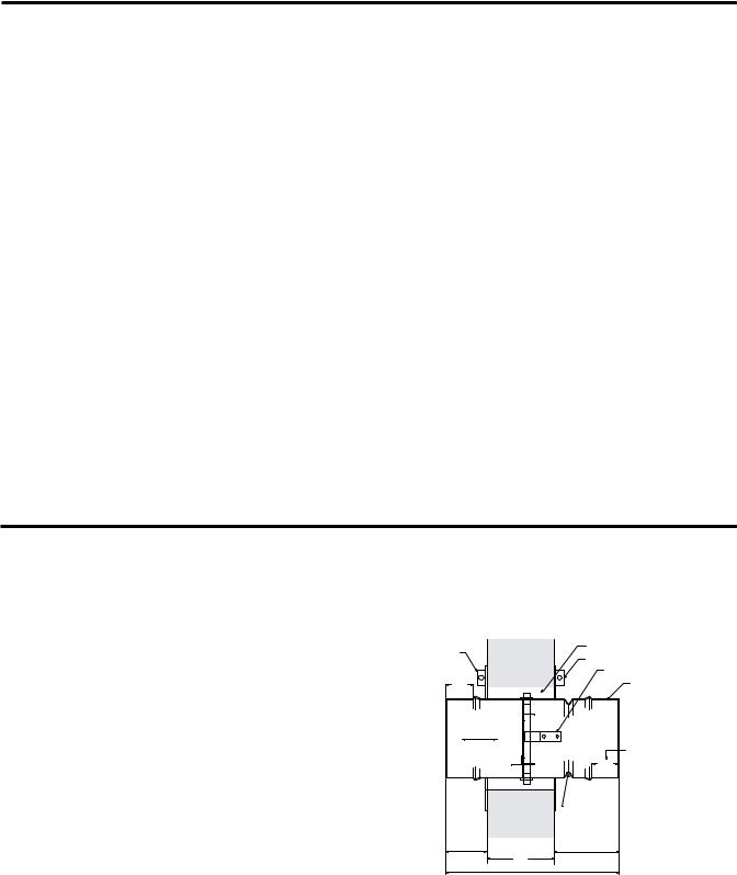
Table of Contents |
|
Pre-Installation Guidelines ................................................................................... |
2 |
Installation ......................................................................................................... |
2-4 |
Maintenance ......................................................................................................... |
4 |
Troubleshooting .................................................................................................... |
4 |
Pre-Installation Guidelines
The basic intent of a proper installation is to secure the fire damper in the opening in such a manner as to prevent distortion and disruption of damper operation. This is accomplished by allowing the fire damper in rated separation openings to expand and for the connecting duct to separate in the event of the collapse of the hanging system. The following items will aid in completing the damper installation in a timely and effective manner.
1)Check the schedules for proper damper locations within the building. Visually inspect the damper for damage and verify that the fusible link is in place or has not separated. Dampers will be supplied with a temperature responsive fusible link device. If fusible link is not present or has separated, replace link. Never install a fire damper without the proper UL approved fusible link in place.
2)Lift or handle damper using the frame. Do not lift damper using blades.
3)Do not install screws into the main body area of the damper frame as screws may interfere with and prevent damper blade from opening and/or closing.
4)Damper must be installed into duct or opening free of distortion or other misalignment. Damper must not be squeezed or stretched into duct or opening. Out of round, racked, twisted or misaligned installations can cause torque requirements to exceed damper design.
5)Damper must be kept clean and protected from dirt, dust and other foreign materials prior to and after installation. Examples of such foreign materials include but are not limited to: 1) Mortar dust 2) Drywall dust 3) Firesafing materials 4) Wall texture and 5) Paint overspray.
6)Damper should be sufficiently covered to prevent overspray if wall texturing or spray painting will be performed within 5 feet of the damper. Excessive dirt or foreign material deposits on damper can cause torque requirements to exceed damper design.
7)Caulking is not allowed between the damper sleeve and the wall or floor opening (annular space). However, caulking may be applied to the retaining plates and a field-applied sealant may be required for the damper sleeve and transitions to meet certain duct leakage standards.
8)ACCESS: Suitable access (such that fusible links can be maintained) must be provided for damper inspection and servicing. Where it is not possible to achieve sufficient size access, it will be necessary to install a removable section of duct. (Refer to NFPA 90A).
9)The Code Authority Having Jurisdiction (AHJ) must evaluate and provide approval of final installation where variations to these instructions are necessary.
Installation - Failure to follow these instructions will void all warranties.
These instructions apply to 11/2 hour rated fire dampers mounted (blades must be horizontal) in: 1) masonry, block or stud walls and 2) concrete floors or ceilings. Specific requirements in these instructions are mandatory. Dampers must be installed in accordance with these instructions to meet the requirements of UL 555. The installation of the damper and all duct connections to the damper sleeve shall conform to the latest editions of NFPA 90A, Standard for the Installation of Air Conditioning and Ventilating Systems, and the SMACNA Fire, Smoke and Radiation Damper Installation Guide, and UL Classifications R13317.
1.CLEARANCES REQUIRED BETWEEN FIRE DAMPER SLEEVES AND WALL/FLOOR OPENINGS
Fire damper assemblies expand during periods of intense heat. Therefore, it is essential that openings in walls or floors be larger than the fire damper assembly to allow for this expansion. The wall/floor opening must be a minimum of 7/8 in.(22mm) larger than the outside diameter of the damper. Refer to Section 4 for additional installation considerations.
|
|
CLEARANCE FOR |
||
RETAINER PLATE |
EXPANSION |
|
||
RETAINER PLATE |
||||
(OPTIONAL) |
||||
|
|
BLADE LATCH |
||
DUCT CONNECTION |
2 in. |
|
ACCESS DOOR TO BE ON |
|
AREA |
|
SAME SIDE AS BLADE LATCH |
||
|
|
|||
|
AIRFLOW |
|
|
|
|
|
|
DUCT CONNECTION |
|
|
|
2 in. |
AREA |
|
|
|
|
||
|
|
DO NOT PLACE RETAINER |
||
|
|
PLATE IN THIS GROOVE |
||
|
6 in. max. |
6 in. max. |
|
|
|
|
TW |
|
|
|
|
SLEEVE LENGTH |
|
|
2 |
Fig. 1 |
|
 Loading...