


PN 452413
® |
Canopy Type Kitchen Hoods |
|
Installation, Operation and Maintenance Manual
Please read and save these instructions. Read carefully before attempting to assemble, install, operate or maintain the product described. Protect yourself and others by observing all safety information. Failure to comply with instructions could result in personal injury and/or property damage! Retain instructions for future reference.
Please record the Serial, Model #, and Mark for the hood and other equipment for future reference.
Serial #: ________________________ |
Model #:_______________________ |
Mark:__________________ |
|
Serial #: ________________________ |
Model #:_______________________ |
Mark:__________________ |
|
Serial #: ________________________ |
Model #:_______________________ |
Mark:__________________ |
|
Serial #: ________________________ |
Model #:_______________________ |
Mark:__________________ |
|
Serial #: ________________________ |
Model #:_______________________ |
Mark:__________________ |
|
Serial #: ________________________ |
Model #:_______________________ |
Mark:__________________ |
|
Serial #: ________________________ |
Model #:_______________________ |
Mark:__________________ |
|
Serial #: ________________________ |
Model #:_______________________ |
Mark:__________________ |
|
Serial #: ________________________ |
Model #:_______________________ |
Mark:__________________ |
|
Serial #: ________________________ |
Model #:_______________________ |
Mark:__________________ |
|
Serial #: ________________________ |
Model #:_______________________ |
Mark:__________________ |
|
|
|
|
|
1 |
Canopy Hood |
|
|

Table of Contents
Receiving and Handling . . . . . . . . . . . . . . . . . . . . . . . . . . . . . . . 4
Storage . . . . . . . . . . . . . . . . . . . . . . |
. . . . . . . . . . . . . . . 4 |
||||||
Hood Weights . . . . . . . . . . . . . . . . . . . . . . . . . . . . . . . . . . . 4 |
|||||||
Installation . . . . . . . . . . . . . . . . . . . . . |
. . . |
. . . . . . . . . |
|
. |
. |
|
. 5 |
Hood Installation Overview . . . . . . . . . . . . . . |
. . . |
. . . . . . . . . |
. |
|
. |
. |
5 |
Filler Panels . . . . . . . . . . . . . . . . . . . . |
. . . . . . . . . . . . . . . 5 |
||||||
Hood Hanging Height . . . . . . . . . . . . . . . . . . . . . . . . . . . . . . . . 6 |
|||||||
Continuous Capture Plenum . . . . . . . . . . . . . . |
. . . |
. . . . . . . . . |
|
. |
. |
|
. 6 |
Double Island Style Hood . . . . . . . . . . . . . . . |
. . . |
. . . . . . . . . |
|
. |
. |
|
. 6 |
U-Channel Strips . . . . . . . . . . . . . . . . . . |
. . . |
. . . . . . . . . |
. |
|
. |
. |
6 |
Electrical Connections . . . . . . . . . . . . . . . . |
. . . . . . . . . . . . . . . 7 |
||||||
Ductwork . . . . . . . . . . . . . . . . . . . . . . . . . . . . . . . . . . . . . 7 |
|||||||
Installation Instructions for the External Supply Plenums . . |
. . . |
. . . . . . . . . |
. |
|
. 8 - 9 |
||
Installation Instructions for the Back Supply Plenum (BSP) . |
. . . |
. . . . . . . . . |
. |
|
. |
. 10 |
|
Installing the Supply Duct Collar . . . . . . . . . . . . |
. . . |
. . . . . . . . . |
. |
|
. |
. 10 |
|
Hanging the Back Supply Unit . . . . . . . . . . . . . |
. . . |
. . . . . . . . . |
. |
|
. |
. 10 |
|
Hanging the Hood . . . . . . . . . . . . . . . . . . |
. . . |
. . . . . . . . . |
|
. |
. |
|
11 |
Air Diffusers . . . . . . . . . . . . . . . . . . . . |
. . . |
. . . . . . . . . |
. |
|
. |
. 11 |
|
Enclosure Panel Installation Instructions . . . . . . . . . |
. . . |
. . . . . . . . . |
|
. |
. |
|
12 |
End Skirt Installation Instructions . . . . . . . . . . . . |
. . . |
. . . . . . . . . |
|
. |
. |
|
13 |
Backsplash Panel Installation Instructions . . . . . . . . |
. . . |
. . . . . . . . . . 14 - 15 |
|||||
Duct Collar Installation Instructions for GH, GK and GX Series |
Hoods . . . . . . . . . . . . 16 |
||||||
Exhaust Air Balancing Baffle . . . . . . . . . . . . . . |
. . . |
. . . . . . . . . |
|
. |
. |
|
17 |
Balancing the Kitchen Exhaust . . . . . . . . . . . . . |
. . . |
. . . . . . . . . |
|
. |
. |
|
18 |
Baffle Filters (GH Series) . . . . . . . . . . . . |
. . . |
. . . . . . . . . |
. |
18 - 21 |
|||
High Velocity Cartridge Filters (GK Series) . . . . . |
. . . |
. . . . . . . . . |
. |
22 - 23 |
|||
High Efficiency Filters (GX Series) . . . . . . . . . |
. . . |
. . . . . . . . . |
|
24 - 25 |
|||
Short Circuit Hoods . . . . . . . . . . . . . . |
. . . |
. . . . . . . . . |
. |
|
. |
. 26 |
|
Fire Suppression Wiring Diagrams . . . . . . . . . . . |
. . . |
. . . . . . . . . |
. |
27 - 28 |
|||
Overall Wiring Plan View . . . . . . . . . . . . . . . |
. . . |
. . . . . . . . . |
. |
|
. |
. 29 |
|
Wiring for Hood Switch Panels . . . . . . . . . . . . . |
. . . |
. . . . . . . . . |
|
. |
. |
|
30 |
Circuit Diagram . . . . . . . . . . . . . . . . . . . |
. . . |
. . . . . . . . . |
. |
|
. |
. 31 |
|
2 Canopy Hood
®

Table of Contents
Maintenance . . . . . . . . . . . . . . . . . . . . . . . . . . . . . . . . . . . 32 Grease Grabber™ Cleaning and Maintenance . . . . . . . . . . . . . . . . . . . 33 - 34 Filter Cleaning Frequency Chart . . . . . . . . . . . . . . . . . . . . . . . . . . . 35 Troubleshooting Guide . . . . . . . . . . . . . . . . . . . . . . . . . . . . . 36 - 37 Replacement Parts . . . . . . . . . . . . . . . . . . . . . . . . . . . . . . 38 - 39 Warranty . . . . . . . . . . . . . . . . . . . . . . . . . . . . . . . . . . . . 40
3 Canopy Hood
®

Receiving and Handling
Upon receiving the equipment, check for both obvious and hidden damage. If damage is found, record all necessary information on the bill of lading and file a claim with the final carrier. Check to be sure that all parts of the shipment, including accessories, are accounted for.
STORAGE
If a kitchen hood must be stored prior to installation it must be protected from dirt and moisture. Indoor storage is recommended. For outdoor storage, cover the hood with a tarp to keep it clean, dry, and protected from UV (Ultra Violet) Radiation damage.
Improper storage which results in damage to the unit will void the warranty.
HOOD |
|
|
HOOD DEPTH (MULTIPLY BY LENGTH) FOR HOOD WEIGHT |
|
|
||||||
|
|
|
|
|
|
|
|
|
|
||
MODEL |
3 ft. |
3.5 ft |
4 ft |
4.5 ft |
5 ft |
5.5 ft |
6 ft |
6.5 ft |
7 ft |
7.5 ft |
|
|
|
||||||||||
|
|
.914 m |
1.067 m |
1.2192 m |
1.3716 m |
1.524 m |
1.6764 m |
1.8288 m |
1.9812 m |
2.1336 m |
2.286 m |
|
|
|
|
|
|
|
|
|
|
|
|
GH, GK, |
30 lbs/ ft. |
32 lbs/ft |
35 lbs/ft |
38 lbs/ft |
40 lbs/ft |
|
|
|
|
|
|
44.64 |
47.62 |
52.08 |
56.54 |
59.52 |
|
|
|
|
|
||
GXEW |
|
|
|
|
|
||||||
kg/m |
kg/m |
kg/m |
kg/m |
kg/m |
|
|
|
|
|
||
|
|
|
|
|
|
|
|||||
|
|
|
|
|
|
|
|
|
|
|
|
GH, GX, |
36 lbs/ft |
38 lbs/ft |
41 lbs/ft |
44 lbs/ft |
46 lbs/ft |
|
|
|
|
|
|
53.57 |
56.44 |
61.01 |
65.47 |
68.45 |
|
|
|
|
|
||
GXDW |
|
|
|
|
|
||||||
kg/m |
kg/m |
kg/m |
kg/m |
kg/m |
|
|
|
|
|
||
|
|
|
|
|
|
|
|||||
|
|
|
|
|
|
|
|
|
|
|
|
GH, GK, |
|
40 lbs/ft |
44 lbs/ft |
48 lbs/ft |
52 lbs/ft |
|
|
|
|
|
|
|
59.52 |
65.47 |
71.42 |
77.38 |
|
|
|
|
|
||
GXFW |
|
|
|
|
|
|
|||||
|
kg/m |
kg/m |
kg/m |
kg/m |
|
|
|
|
|
||
|
|
|
|
|
|
|
|
||||
|
|
|
|
|
|
|
|
|
|
|
|
GH, GK, |
|
48 lbs/ft |
51 lbs/ft |
54 lbs/ft |
57 lbs/ft |
|
|
|
|
|
|
|
71.42 |
71.89 |
81.35 |
84.82 |
|
|
|
|
|
||
GXCW |
|
|
|
|
|
|
|||||
|
kg/m |
kg/m |
kg/m |
kg/m |
|
|
|
|
|
||
|
|
|
|
|
|
|
|
||||
|
|
|
|
|
|
|
|
|
|
|
|
GH, GK, |
|
44 lbs/ft |
48 lbs/ft |
52 lbs/ft |
56 lbs/ft |
|
|
|
|
|
|
|
65.47 |
71.42 |
77.38 |
83.33 |
|
|
|
|
|
||
GXSW |
|
|
|
|
|
|
|||||
|
kg/m |
kg/m |
kg/m |
kg/m |
|
|
|
|
|
||
|
|
|
|
|
|
|
|
||||
|
|
|
|
|
|
|
|
|
|
|
|
|
|
39 lbs/ft |
41 lbs/ft |
44 lbs/ft |
47 lbs/ft |
49 lbs/ft |
|
|
|
|
|
GGEW |
58.03 |
61.01 |
65.47 |
69.94 |
72.91 |
|
|
|
|
|
|
|
|
kg/m |
kg/m |
kg/m |
kg/m |
kg/m |
|
|
|
|
|
|
|
|
|
|
|
|
|
|
|
|
|
|
|
45 lbs/ft |
47 lbs/ft |
50 lbs/ft |
53 lbs/ft |
55 lbs/ft |
|
|
|
|
|
GGDW |
66.96 |
69.94 |
74.40 |
78.86 |
81.84 |
|
|
|
|
|
|
|
|
kg/m |
kg/m |
kg/m |
kg/m |
kg/m |
|
|
|
|
|
|
|
|
|
|
|
|
|
|
|
|
|
|
|
|
49 lbs/ft |
53 lbs/ft |
57 lbs/ft |
61 lbs/ft |
|
|
|
|
|
GGFW |
|
72.91 |
78.86 |
84.82 |
90.77 |
|
|
|
|
|
|
|
|
|
kg/m |
kg/m |
kg/m |
kg/m |
|
|
|
|
|
|
|
|
|
|
|
|
|
|
|
|
|
|
|
|
57 lbs/ft |
60 lb/ft |
63 lbs/ft |
66 lbs/ft |
|
|
|
|
|
GGCW |
|
84.82 |
89.28 |
93.74 |
98.21 |
|
|
|
|
|
|
|
|
|
kg/m |
kg/m |
kg/m |
kg/m |
|
|
|
|
|
|
|
|
|
|
|
|
|
|
|
|
|
|
|
|
53 lbs/ft |
57 lbs/ft |
61 lbs/ft |
65 lbs/ft |
|
|
|
|
|
GGSW |
|
78.86 |
84.82 |
90.77 |
96.72 |
|
|
|
|
|
|
|
|
|
kg/m |
kg/m |
kg/m |
kg/m |
|
|
|
|
|
|
|
|
|
|
|
|
|
|
|
|
|
GH, GK, |
|
|
52 lbs/ft |
54 lbs/ft |
56 lbs/ft |
58 lbs/ft |
61 lbs/ft |
63 lbs/ft |
|
|
|
|
|
77.38 |
81.35 |
83.33 |
86.30 |
90.77 |
93.74 |
|
|
||
GXEV |
|
|
|
|
|||||||
|
|
kg/m |
kg/m |
kg/m |
kg/m |
kg/m |
kg/m |
|
|
||
|
|
|
|
|
|
||||||
|
|
|
|
|
|
|
|
|
|
|
|
GH, GK, |
|
|
61 lbs/ft |
66 lbs/ft |
68 lbs/ft |
72 lbs/ft |
75 lbs/ft |
79 lbs/ft |
|
|
|
|
|
90.77 |
98.21 |
101.18 |
107.14 |
111.6 |
117.55 |
|
|
||
GXFV |
|
|
|
|
|||||||
|
|
kg/m |
kg/m |
kg/m |
kg/m |
kg/m |
kg/m |
|
|
||
|
|
|
|
|
|
||||||
|
|
|
|
|
|
|
|
|
|
|
|
GH, GK, |
|
|
|
|
|
|
81 lbs/ft |
84 lbs/ft |
87 lbs/ft |
90 lbs/ft |
|
|
|
|
|
|
|
120.53 |
124.99 |
129.46 |
133.92 |
||
GXCV |
|
|
|
|
|
|
|||||
|
|
|
|
|
|
kg/m |
kg/m |
kg/m |
kg/m |
||
|
|
|
|
|
|
|
|
||||
|
|
|
|
|
|
|
|
|
|
|
|
GH, GK, |
|
|
|
66 lbs/ft |
69 lbs/ft |
72 lbs/ft |
76 lbs/ft |
79 lbs/ft |
|
|
|
|
|
|
98.21 |
102.67 |
107.14 |
113.09 |
117.55 |
|
|
||
GXSV |
|
|
|
|
|
||||||
|
|
|
kg/m |
kg/m |
kg/m |
kg/m |
kg/m |
|
|
||
|
|
|
|
|
|
|
|||||
|
|
|
|
|
|
|
|
|
|
|
|
|
|
|
|
|
|
|
|
|
|
|
|
4 |
Canopy Hood |
|
|
|
|
|
|
|
|
® |
|
Installation
NOTE: If you have a Back |
|
|
|
|
|
|
|
|
|
Supply Plenum (BSP), this must |
|
|
|
|
|
|
|
|
|
|
|
|
|
|
|
|
|
|
|
be installed before the hood. |
|
|
|
|
|
|
|
|
Fig. 1 |
Please see Page 10. |
|
|
|
|
|
|
|
|
|
|
|
|
|
|
|
|
|
|
|
For Wall/Single Island Style |
|
|
|
|
|
|
|
|
|
Hoods, prior to installation, |
|
|
|
|
|
|
|
|
|
check with local authorities |
|
|
|
|
|
|
|
|
Bottom |
having jurisdiction on clearances |
|
|
|
|
|
|
|
|
|
to combustible surfaces, etc. |
|
|
|
|
|
|
|
|
|
With the hood still inside its |
|
|
|
|
|
|
|
|
|
packing crate, position the unit |
|
|
|
|
|
|
|
|
|
beneath its installation location. |
Pallet |
|
|
|
|
|
|
||
Carefully remove the packing |
|
|
|
|
|
|
|
|
Protective Material |
|
|
|
|
|
|
|
|
||
crate. Place some protective |
|
|
|
|
|
|
|
|
|
|
|
|
|
|
|
|
|
|
|
material on the floor next to
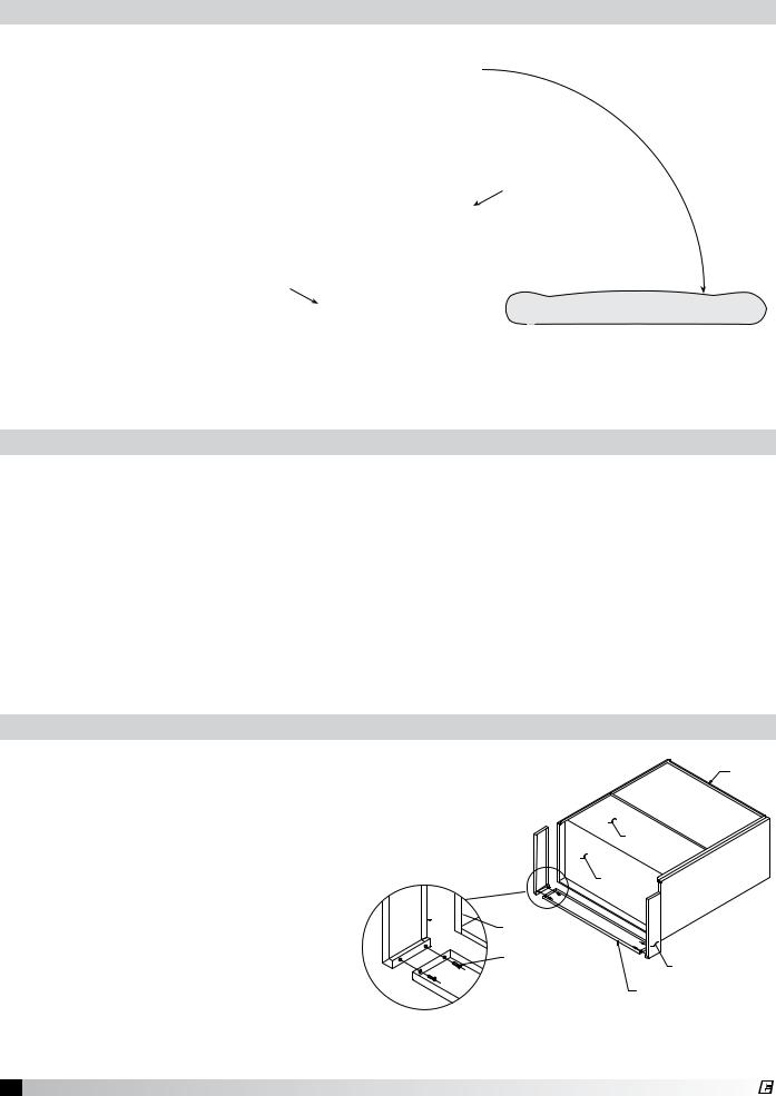
the crate to avoid damaging the hood as it is tipped on its side; Fig. 1. Tip the hood carefully onto the protective material. If you have filler panels, install them now; Fig. 2. If you have integral filler panels, no additional installation is needed.
Hood Installation Overview
If a Back Supply Plenum is provided, install first. Before raising hood, insert 1/2 in. (12.7 mm) diameter threaded rod (by others) into hanger brackets on hood top. Check the engineering drawings or UL label located on the inside of the hood for proper hood height above finished floor. Install filler panels if needed. Raise and hang hood from adequate roof or ceiling supports All hanger brackets must be used and the hood must be properly supported while lifting to prevent damage or distortion to the hood. The hood must be hung level to operate properly. After hood is secured, make the exhaust duct connections. The fire system distributor must be contacted at this time. After the fire system has been installed, mount the enclosures, then the supply plenums. If an Horizontal Supply Plenum is provided, it should be installed before the enclosures. The hood and accessories are now installed. Finally, make the electrical connections from switches to fans and complete the fire system circuits as required by the job specification.
Filler Panel Installation Instructions
1.Uncrate the hood and lay it on the floor with protective material between the hood and the floor. (Fig. 1)
2.Bolt the filler panels together with 5/16 in. bolts provided in the hardware package.
3.Position the filler panels to the hood back, and tack-weld them into place. (Fig. 2)
4.To allow for ease of cleaning, caulk the external seams with NSF Approved silicone caulk (GE SCS1009, or its equivalent). The caulk is not provided.
 TACK-WELDED TO HOOD BACK
5/16 IN. X 3/4 IN. BOLTS WITH WASHERS & NUTS
HOOD
HOOD
HOOD
RIGHT FILLER PANEL
BOTTOM FILLER PANEL
Fig. 2
5 Canopy Hood
®

Hood Hanging Height
The hood hanging height is critical, hanging the hood at the incorrect height may significantly reduce the ability for the hood to function properly and may be in violation of codes. The hood hanging height (typically, 78 in. (198.12 cm) above the finished floor) is given on the UL label located on the inside of the hood on the end panel. The hood must be hung level to operate properly. The grease trough is pitched to drain into the grease container.
Double Island Style Hoods
Before hanging the hoods, please verify the hood marks to make sure the correct hood is hung on the correct side.
A double island hood is created by installing two wall style hoods back to back. Use the installation procedure described on page 5 for single island hoods; install and level both hoods. After leveling, secure the hoods together by tack-welding and/or bolting the rear mounting brackets. Caulk this joint with NSF Approved silicone caulk (GE SCS1009 or its equivalent). The caulk is not provided.
Continuous Capture Plenum Hoods
Remove the support angles on the open end panels. (see Fig. 3) Use the installation procedure described on page 4 for single island hoods; install and level both hoods.
After leveling, secure the hoods together by tack-welding and/or bolting the top angles. Fasten the hoods together using u-clips and bolts, (see Fig. 4). Caulk this joint
with NSF Approved silicone caulk (GE SCS1009 or its equivalent). The caulk is not provided.
Fig. 3 |
|
|
|
FRONT |
|
|
|
HOOD |
1. REMO |
|
|
2. RAISE |
|
|
AND SU |
|
|
3. FASTEN |
|
|
4. FASTEN |
|
|
& CAP |
CAULK |
|
5. CAULK |
BOLT |
|
|
ACORN NUT |
|
|
Fig. 4 |
U-CLIP |
|
|
Installing U-Channel Strip
1.After the hood is hung in position and leveled, apply caulk to the inside edge of the double island clip. (Fig. 5)
2.Position and install the clip by tapping into position along clip (friction fit).
3.Caulk edges to seal out grease and allow for ease of cleaning. Caulk with NSF Approved silicone caulk
(GE SCS1009 or its equivalent). The caulk is not provided.
Fig. 5
-1B |
|
|
|
ITEM |
|
|
|
|
|
A |
|
|
1 |
|
|
|
- |
|
|
|
ITEM |
HOOD-1A |
|
|
|
|
T |
|
|
ON |
|
|
|
FR |
HOOD-1B |
|
|
HOOD |
|
|
|
|
|
|
|
|
SILICONE CAULK |
|
|
|
(GE SCS1009) |
|
|
|
DOUBLE ISLAND CLIP |
DOUBLE ISLAND CLIP |
DETAIL A |
|
|
6 Canopy Hood
®

Note: The installation of the canopy hoods shall be in accordance with NFPA 96 (latest edition), Standard for Ventilation Control & Fire Protection of Commercial Cooking Operations.
After the hood is installed, remove all protective plastic.
Note: Greenheck does not recommend walking or standing on the hood top as damage can result. If you must walk on the hood top, protect the hood with additional support or planks for flooring.
Electrical Connections
Access for wiring the hood control panel (when applicable) is provided by a junction box located on top of the hood when the control panel is mounted in the hood, or by the switch junction box when the control panel is mounted in the fire protection cabinet. The box is labeled “Control Voltage Wiring to Roof Top Fan Package”. Use minimum 14 AWG copper wire. After all the wiring is completed, install the light bulbs (light bulbs not provided; standard light bulbs up to 100 watt may be used).
Caution: For multiple hood systems that have more than 14 lights total (incandescent or fluorescent), the hood lights must be wired to multiple circuits. Each circuit must have less than 14 lights total.
Standard Greenheck light switches shipped on hoods are rated for 15 amps and shall not have more than 14 lights connected to them. Higher amperage switches are available upon special request.
Ductwork
Exhaust
As specified in NFPA 96, Ch. 7.5 (latest edition), exhaust duct systems must be constructed in the following manner:
Materials. Ducts shall be constructed of and supported by carbon steel not less than 1.37 mm (0.054 in.) (No. 16 MSG) in thickness or stainless steel not less than 1.09 mm (0.043 in.) (No. 18 MSG) in thickness.
Installation: All seams, joints, penetrations, and duct to hood collar connections shall have a liquid tight external weld. If you have an Automatic Fire Damper please refer to that manual for installation instructions now.
Supply
Supply ductwork (where applicable) should be connected to the hood in a manner approved by the local code authorities.
Note: For hoods with fire dampers in the exhaust and supply duct collars, an access panel for cleaning and inspection shall be provided in the duct. This panel shall be as close to the hood as possible but should not exceed 18 in. (45.72 cm).
For proper installation of duct collars when they are shipped unattached, see page 16.
7 Canopy Hood
®
Installing External Supply Plenums
Fig. 6 |
|
|
OPTION #2 |
|
|
|
|
|
|
|
UNI-STRUT SUPPLIED BY OTHERS |
OD |
|
|
|
Y OTHERS |
|
|
TOP VIEW |
|
|
|
|
|
CABINET |
|
HOOD |
|
|
OPTION #1 |
|
|
|
FOR PLENUMS <= 96" |
|
|
|
2 CLIPS ARE NEEDED |
|
|
|
FOR PLENUMS > 96" |
|
|
UTILITY |
|
|
|
|
3 CLIPS ARE NEEDED |
|
|
|
THE THIRD CLIP IS LOCATED |
|
|
|
IN THE CENTER OF THE PLENUM |
|
|
|
LENGTH |
|
|
|
|
|
|
OPTIONAL |
|
OPTION #1 |
|
|
ATTACH HANGING CLIP TO |
|
|
|
HOOD STANDING SEAM WITH |
|
|
|
THE SUPPLIED "C" CLAMPS |
|
|
|
(OPTIONAL: DRILL AND BOLT A |
|
|
|
1/4-20 SS BOLT THROUGH |
|
|
|
THE CLIP AND HOOD STANDING |
|
|
|
SEAM) |
|
|
|
|
11.5 
23.5
TOP VIEW SUPPLY PLENUM
HANGER BRACKET
Using the Supply Plenum Clip
Note: The supply plenum is provided with plenum clips that assist in hanging the plenum. The plenum should not be hung only with the plenum clips, threaded rod or uni-strut must also be used.
1.Bolt the hanging clip to the supply plenum. Two clips are needed for plenums less than 96 in. (243.84 cm) long and three for plenums greater than 96 in. (243.84 cm). The third clip is located in the center of the plenum length. If there is a utility cabinet, the hanging clip should be 23.5 in. (59.69 cm) from the end to the hood.
2.Using the c-clamps provided, clamp the supply plenum hanging clip to the hood standing seam. Option: Drill and bolt a 1/4-20 SS bolt through the clip and hood standing seam.
OPTION #1
HANGING CLIP COULD BE 23.5" FROM END IF THERE IS A UTILITY CABINET ON THE END OF THE HOOD
|
"C" CLAMP |
|
OPTION #1 |
|
|
HOOD STANDING SEAM |
|
|
|
HANGING CLIP |
|
|
|
|
|
|
|
HANGING CLIP BOLTED TO PLENUM SHELL |
|
|
|
HANGING CLIP |
|
Supply Plenum Clip |
HOOD FRONT |
SUPPLY PLENUM SHELL |
|
|
|
Fig. 7 |
|
|
|
|
|
THREADED ROD
OPTION #2
THE UNI-STRUT (U-CHANNEL) THAT HOLDS THE HOOD UP CANTILEVERS OVER THE END OF THE HOOD AND IS MOUNTED TO THE ASP HANGER BRACKETS
OPTION #3
THREADED ROD SUPPLIED BY OTHERS
Using the Uni-strut
1.The uni-strut (supplied by others) that holds the hood up cantilevers over the end of the hood and is mounted to the supply plenum hanger brackets.
END VIEW
HOOD |
Fig. 8 |
|
8 Canopy Hood
®
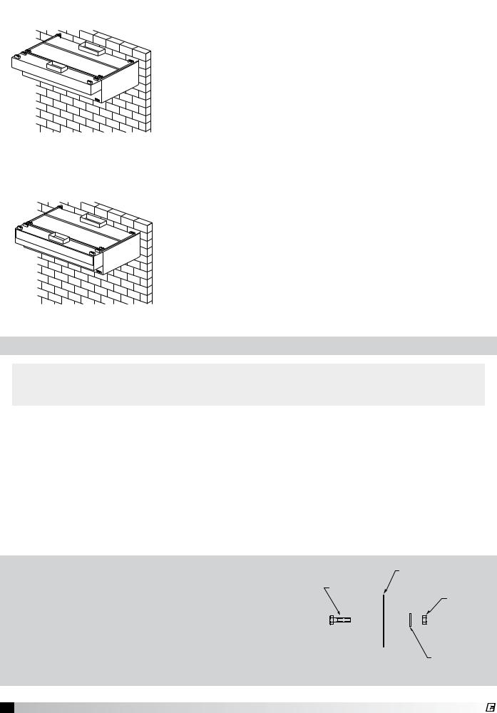
Fig. 9
ASP - Air Curtain Supply Plenum
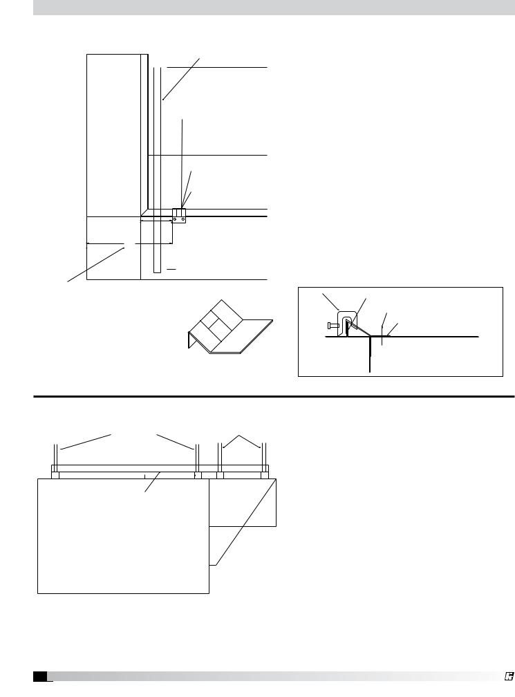
1.Insert 1/2 in. (12.7 mm) diameter threaded rod (by others) into hanger brackets on the supply plenum top. Raise and hang the external supply plenum from adequate roof or ceiling supports.
2.The external supply plenum should be resting lightly against the hood. The hood is used to position the plenum only, it is not intended to support the plenum. All hanger brackets must be used and the plenum must be properly supported while lifting to prevent damage or distortion. The supply plenum must be hung level to operate properly.
(Optional fastening of supply plenum to hood. See directions below).
Fig. 10 |
3. It is recommended that caulk be applied at the mating seams |
|
and surfaces of the plenum, the hood, and the wall. If the |
|
supply plenum is next to a wall, you will also need to caulk |
|
around the surface next to the wall. Caulk the joints with NSF |
|
Approved silicone caulk (GE SCS1009, or its equivalent). The |
|
caulk is not provided. |
Installing the Supply Duct Collar to the Plenum
1.Place the duct collar(s) over the opening, fastening with tackwelds at 1 to 2 in. (2.54 to 5.08 cm) intervals, or sheet metal
screws at 3 to 6 in. (7.62 to 15.24 cm) intervals.
HSP or VSP - Variable Supply Plenum
External Supply Plenum Weights, Dimensions, and Supply Rates
|
Weight |
|
Width |
Height |
Length per |
|
|
||||
External Supply |
|
section |
|
Recommended |
|||||||
|
|
|
|
|
|
|
|
||||
Plenum Type |
(lbs/ft) |
(kg/ft) |
(in) |
|
(mm) |
(in) |
(mm) |
(ft) |
(m) |
|
Supply Rate |
|
|
|
|
||||||||
|
|
|
|
|
|
|
|
|
|
|
|
Back Supply |
35.0 |
15.878 |
6 |
|
152.4 |
Variable |
Variable |
3 to 16 |
.91 to |
|
145 cfm/ft |
|
4.88 |
|
(246.36 m3/hr) |
||||||||
Air Curtain Supply |
9.5 |
4.31 |
14 |
|
355.6 |
10 |
254 |
3 to 16 |
.91 to |
|
110 cfm/ft |
• 14 inch |
|
4.88 |
|
(186.89 m3/hr) |
|||||||
Air Curtain Supply |
12.5 |
5.67 |
24 |
|
609.6 |
10 |
254 |
3 to 16 |
.91 to |
|
145 cfm/ft |
• 24 inch |
|
4.88 |
|
(246.36 m3/hr) |
|||||||
|
|
|
|
|
|
|
|
|
|
curtain |
0-80 cfm/ft |
Variable Supply |
16.0 |
7.26 |
12 |
|
304.8 |
18 |
457.20 |
3 to 16 |
.91 to |
(0-135.92 m3/hr) |
|
|
4.88 |
face |
80-160 cfm/ft |
||||||||
|
|
|
|
|
|
|
|
|
|||
|
|
|
|
|
|
|
|
|
|
(135.92 -271.84 m3/hr) |
|
Horizontal Supply |
14.0 |
6.35 |
12 |
|
304.8 |
18 |
457.20 |
3 to 16 |
.91 to |
|
150 cfm/ft |
|
4.88 |
|
(254.85 m3/hr) |
||||||||
Using the UL Listed Fastener Provided
1.Drill a 9/32 in. hole for the 1/4 in. bolt from the inside of the supply plenum to inside the hood. Fasteners are to be located max. 6 in. (15.24 cm) from the end of the hood with max. spacing between bolts 36 in. (91.44 cm)
DO NOT include utility cabinets or fillers when figuring bolt placement. DO NOT bolt the supply plenum to a fire/utility cabinet.
2.Push bolt through hole, attach the washer and nut.
3.Hand tighten, then use a wrench until fully tightened. Caulk around bolts from inside of hood as necessary.
HOOD
1/4 - 20 UNC - 2A
SS BOLT
1/4 IN. SS NUT
SS FLAT WASHER
Fig. 11
9 Canopy Hood
®
Installing the Back Supply Plenum
Installing the Supply Duct Collar |
|
|
|
1. |
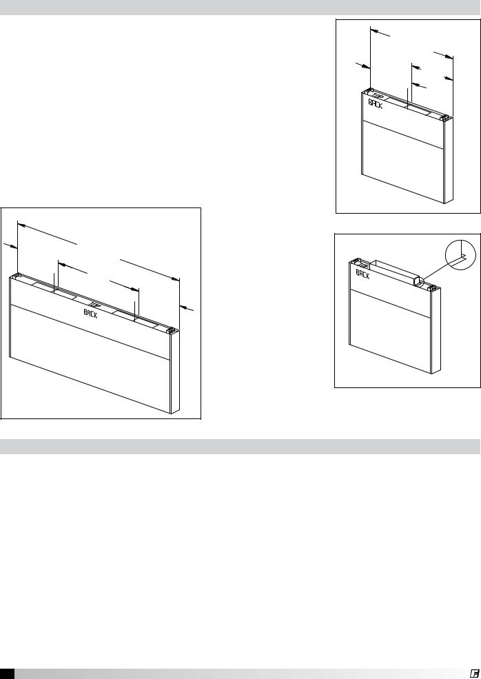
Find the center of the back supply plenum. |
L (MODULE LENGTH) |
|
2. |
If the back supply plenum is less than 9 ft. 10 in. (299.72 cm) long, |
|
|
|
cut opening at the suggested location, centering the opening over |
L/2 |
L/2 |
|
the center of the back supply plenum. (Fig. 12) |
|
|
3.If the back supply plenum is greater than 9 ft. 10 in. (299.72 cm) long, divide the length of the back supply by four. This will give you the center of each half. Cut openings at the suggested location, centering the duct collar over the center measurement of each half. (Fig. 13)
4.Place the duct collar(s) over the opening, fastening with screws or tack-welds every 4 to 6 in. (10.16 to 15.24 cm). (Fig. 14)
|
|
Fig. 12 |
L/4 |
|
• The 4 in. (10.16 cm) |
L (MODULE LENGTH) |
high duct collar is to |
|
|
|
|
|
|
be attached to the |
|
L/2 |
back supply. |
|
|
L/4 |
|
|
Fig. 14 |
Fig. 13 |
|
|
Hanging the Back Supply Plenum
5.Hang the back supply plenum from the ceiling.
(The back supply plenum needs to be mounted 31.25 in. (79.375 cm) above the floor (based upon a canopy hood that will be hung at 78 in. (198.12 cm) above the finished floor. This is measured from the lowest rear edge of the back supply plenum to the finished floor. Leave 6 to 10 in. (15.24 to 25.4 cm) of space below the plenum for access to the air diffusers.)
6.Fasten the Back Supply to the wall, going through the lower Back Supply wall. (Fig. 15)
•These fasteners are to help maintain the location of the Back Supply, and are not intended to hold the weight of the Back Supply Unit.
•The fasteners should not interfere with the removable air diffusers.
•The 31.25 in. (79.375 cm) height is based upon the canopy hood hanging height of 78 in.
(198.12 cm) from the finished floor to the bottom of the hood.
10 Canopy Hood
®

Hanging the Hood
Before hanging the hood according to the hood installation instructions, please check the following:
1.Make sure the back supply plenum is properly secured, as described in steps 5 and 6, page 10.
2.If the ductwork for the back supply will not interfere with the hood installation, it should be connected now.
3.Any filler panels should be attached to the hood before the hood installation.
See page 5 for instructions.
4.Lift the hood, and position it so the filler panels are resting lightly on the top outside edges of the back supply. The back supply is used to position the hood only, it is not intended to hold any hood weight. (Fig. 16)
5.Connect the remaining ductwork for the
back supply and the hood. It is recommended that caulk be applied at the mating seams and surfaces of the back supply, the hood, and the wall.
Fig. 15
Fasteners holding the back supply to the wall
31.25 in. |
Critical |
Dimension |
Fig. 16 |
Air Diffusers
The air diffusers, located at the bottom of the back supply (Fig. 17), will need to be cleaned as often as the application dictates. Inspect periodically to determine the cleaning schedule.
1.To clean the air diffusers, unfasten the screws. Remove the air diffusers from the Back Supply Unit, and wash in the sink or dishwasher.
2.Insert the air diffusers at an angle from the bottom, and rotate so the forms are downward. Rest the diffuser on the internal angles. (Fig. 18)
3.Refasten with the stainless steel screws.
Fig. 17 |
Removable Air Diffusers |
Fig. 18 |
11 Canopy Hood
®
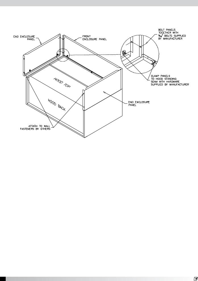
Installing Enclosure Panels
Before installing the enclosure panels, make sure the hood is hung in position with all the ductwork attached and electrical connections completed.
Fig. 19
1.Position the end enclosure panels on the hood, and clamp into place with clamps provided or tackweld the panels into place (Fig 19).
2.Fasten the end enclosure panels to the wall, method depends on wall construction. (fasteners are not provided)
If the hood is a double island, bolt the end enclosure panels together. (fasteners are not provided)
3.Position the front enclosure panel(s) on the hood, and bolt to the end enclosure panels with the 5/16 in. bolts provided in the hardware package.
4.Tack-weld or clamp the front enclosure panel(s) to the hood. If clamps are used, they must be positioned 4 in. (100 mm) from the ends, and in the center of the front enclosure panel.
5.To allow for ease of cleaning, caulk the external seams with NSF Approved silicone caulk (GE SCS1009, or its equivalent). The caulk is not provided.
6.Installation instructions may not be applicable for concrete ceilings.
12 Canopy Hood
®
 Loading...