


INSTRUCTION MANUAL
Wingspan: 81 in [2055 mm]
Wing Area: 1138 sq in [73.4 dm2]
Weight: 12.5 – 15.25 lb [5670 – 6860 g]
Wing Loading: 25 – 30 oz/sq ft [77 – 93 g/dm2]
Length: 68 in [1727 mm]
Radio: 4–6 channel, 7 servos minimum
Engine: 1.5 – 1.8 cu in [25 – 30 cc] two-stroke glow engine,
1.8– 2.1 cu in [30 – 36 cc] four-stroke glow engine,
1.9– 2.6 cu in [32 – 43 cc] gasoline engine
WARRANTY
Great Planes® Model Manufacturing Co. guarantees this kit to be free from defects in both material and workmanship at the date of purchase. This warranty does not cover any component parts damaged by use or modification. In no case shall Great Planes’ liability exceed the original cost of the purchased kit. Further, Great Planes reserves the right to change or modify this warranty without notice.
In that Great Planes has no control over the final assembly or material used for final assembly, no liability shall be assumed nor accepted for any damage resulting from the use by the user of the final user-assembled product. By the act of using the user-assembled product, the user accepts all resulting liability.
If the buyer is not prepared to accept the liability associated with the use of this product, the buyer is advised to return this kit immediately in new and unused condition to the place of purchase.
To make a warranty claim send the defective part or item to Hobby Services at the address below:
Hobby Services
3002 N. Apollo Dr., Suite 1
Champaign, IL 61822
USA
Include a letter stating your name, return shipping address, as much contact information as possible (daytime telephone number, fax number, e-mail address), a detailed description of the problem and a photocopy of the purchase receipt. Upon receipt of the package the problem will be evaluated as quickly as possible.
READ THROUGH THIS MANUAL BEFORE STARTING CONSTRUCTION. IT CONTAINS IMPORTANT INSTRUCTIONS AND WARNINGS CONCERNING THE ASSEMBLY AND USE OF THIS MODEL.
Champaign, Illinois
(217) 398-8970, Ext 5 airsupport@greatplanes.com
Entire Contents © Copyright 2006 |
GPMZ0187 for GPMA1411 V1.1 |
TABLE OF CONTENTS |
|
|
INTRODUCTION ............................................................... |
|
2 |
AMA................................................................................... |
|
2 |
IMAA.................................................................................. |
|
3 |
SAFETY PRECAUTIONS.................................................. |
|
3 |
DECISIONS YOU MUST MAKE ........................................ |
|
3 |
Fuel Tank Setup........................................................... |
|
3 |
Building Stand ............................................................. |
|
4 |
Radio Equipment......................................................... |
|
4 |
Engine Recommendations .......................................... |
|
4 |
ADDITIONAL ITEMS REQUIRED..................................... |
|
4 |
Adhesives & Building Supplies.................................... |
|
4 |
Optional Supplies & Tools ........................................... |
|
4 |
IMPORTANT BUILDING NOTES ...................................... |
|
5 |
ORDERING REPLACEMENT PARTS .............................. |
|
5 |
COMMON ABBREVIATIONS............................................ |
|
6 |
METRIC CONVERSIONS ................................................. |
|
6 |
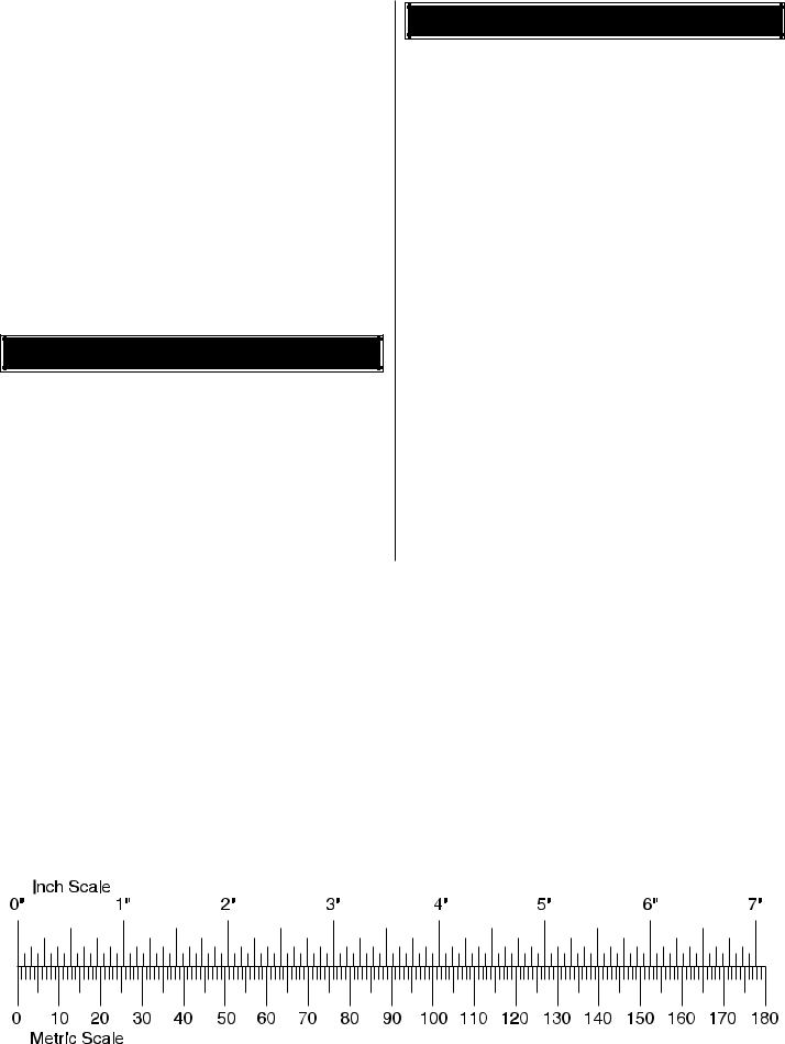
METRIC/INCH RULER ...................................................... |
|
6 |
KIT INSPECTION .............................................................. |
|
7 |
KIT CONTENTS ................................................................ |
|
7 |
PREPARATIONS ............................................................... |
|
8 |
ASSEMBLE THE WING .................................................... |
|
8 |
Install the Ailerons....................................................... |
|
8 |
Install the Aileron Servos & Pushrods......................... |
9 |
|
Finish the Wing.......................................................... |
|
10 |
ASSEMBLE THE FUSELAGE......................................... |
|
11 |
Install the Rudder & Tail Gear ................................... |
|
11 |
Assemble & Install the Main Gear............................. |
|
12 |
Install the Elevators & Stabilizer................................ |
|
13 |
Install the Elevator Servos & Linkage |
....................... |
15 |
Install the Rudder Servos & Linkage |
|
|
(Recommended Glow Engine Installation)...................... |
16 |
|
Install the Rudder Servos & Linkage |
|
|
(Recommended Gas Engine Installation)........................ |
18 |
|
INSTALL THE ENGINE & FUEL TANK........................... |
|
19 |
Glow Engine Installation............................................ |
|
19 |
Install the Throttle Servo (Glow Engine) ................... |
19 |
|
Install the Fuel Tank (Glow Engine) .......................... |
|
20 |
Optional Gas Engine Installation............................... |
|
21 |
Install the Throttle Servo (Gas Engine) ..................... |
23 |
|
Prepare the Cowl....................................................... |
|
23 |
FINISH THE MODEL ....................................................... |
|
25 |
Install the Radio System ........................................... |
|
25 |
Install the Cowl .......................................................... |
|
26 |
Install the Spinner ..................................................... |
|
27 |
Attach the Wing & Canopy ........................................ |
|
27 |
Apply the Decals ....................................................... |
|
28 |
GET THE MODEL READY TO FLY ................................. |
|
28 |
Check the Control Directions .................................... |
|
28 |
Set the Control Throws.............................................. |
|
29 |
Balance the Model (C.G.).......................................... |
|
29 |
Balance the Model Laterally...................................... |
|
30 |
PREFLIGHT..................................................................... |
|
30 |
Identify Your Model .................................................... |
|
30 |
Charge the Batteries ................................................. |
|
30 |
Balance the Propellers .............................................. |
|
30 |
Ground Check ........................................................... |
|
30 |
Range Check............................................................. |
|
30 |
ENGINE SAFETY PRECAUTIONS................................. |
|
31 |
AMA SAFETY CODE (excerpts).................................... |
|
31 |
IMAA SAFETY CODE (excerpts)................................... |
|
32 |
CHECK LIST ................................................................... |
|
33 |
FLYING ............................................................................ |
|
34 |
Fuel Mixture Adjustments.......................................... |
|
34 |
Takeoff ....................................................................... |
|
34 |
Flight.......................................................................... |
|
34 |
Landing...................................................................... |
|
34 |
ENGINE MOUNTING TEMPLATES ........ |
Back Cover Page |
|
INTRODUCTION
The Yak 54 1.60 ARF is a great 3D model mixed with a blend of precision aerobatics. The Yak is fully capable of doing any 3D maneuver that exists or that you can dream of. The Yak is also capable of doing “IMAC” style aerobatics and would be fully acceptable for flying in the “Unlimited” class. The Yak 54 1.60 ARF is the perfect airplane for the modeler that wants to improve his or her 3D skills or wants to start flying IMAC with a low cost budget in mind.
The Yak 54 1.60 ARF is capable of doing blenders, torque rolls, harriers inverted and upright, harrier rolls, waterfalls, walls, parachutes and anything else you can dream up. It is also designed to fly exceptionally precise for doing IMAC aerobatics.
For the latest technical updates or manual corrections to the Yak 54 1.60 ARF, visit the Great Planes web site at www.greatplanes.com. Open the “Airplanes” link, then select the Yak 54 1.60 ARF. If there is new technical information or changes to this model a “tech notice” box will appear in the upper left corner of the page.
AMA
We urge you to join the AMA (Academy of Model Aeronautics) and a local R/C club. The AMA is the governing body of model aviation and membership is required to fly at AMA clubs. Though joining the AMA provides many benefits, one of the primary reasons to join is liability protection. Coverage is not limited to flying at contests or on the club field. It even applies to flying at public demonstrations and air shows. Failure to comply with the Safety Code (excerpts printed in the back of the manual) may endanger insurance coverage. Additionally, training programs and instructors are available at AMA club sites to help you get started the right way. There are over 2,500 AMA chartered clubs across the country. Contact the AMA at the address or toll-free phone number below.
Academy of Model Aeronautics
5151 East Memorial Drive
Muncie, IN 47302
Tele: (800) 435-9262
Fax (765) 741-0057 Or via the Internet at:
http://www.modelaircraft.org
IMPORTANT!!! Two of the most important things you can do to preserve the radio controlled aircraft hobby are to avoid flying near full-scale aircraft and avoid flying near or over groups of people.
2
IMAA
The Great Planes Yak 54 1.60 ARF is an excellent sportscale model and is eligible to fly in IMAA events. The IMAA (International Miniature Aircraft Association) is an organization that promotes non-competitive flying of giantscale models. If you plan to attend an IMAA event, obtain a copy of the IMAA Safety Code by contacting the IMAA at the address or telephone number below.
IMAA
205 S. Hilldale Road
Salina, KS 67401 (913) 823-5569
www.fly-imaa.org/imaa/sanction.html
PROTECT YOUR MODEL, YOURSELF & OTHERS...FOLLOW THESE IMPORTANT SAFETY PRECAUTIONS
1.Your Yak 54 1.60 ARF should not be considered a toy, but rather a sophisticated, working model that functions very much like a full-size airplane. Because of its performance capabilities, the Yak 54 1.60 ARF, if not assembled and operated correctly, could possibly cause injury to yourself or spectators and damage to property.
2.You must assemble the model according to the instructions. Do not alter or modify the model, as doing so may result in an unsafe or unflyable model. In a few cases the instructions may differ slightly from the photos. In those instances the written instructions should be considered as correct.
3.You must take time to build straight, true and strong.
4.You must use an R/C radio system that is in first-class condition, and a correctly sized engine and components (fuel tank, wheels, etc.) throughout the building process.
5.You must correctly install all R/C and other components so that the model operates correctly on the ground and in the air.
6.You must check the operation of the model before every flight to insure that all equipment is operating and that the model has remained structurally sound. Be sure to check clevises or other connectors often and replace them if they show any signs of wear or fatigue.
7.If you are not an experienced pilot or have not flown this type of model before, we recommend that you get the assistance of an experienced pilot in your R/C club for your first flights. If you're not a member of a club, your local hobby shop has information about clubs in your area whose membership includes experienced pilots.
8.While this kit has been flight tested to exceed normal use, if the plane will be used for extremely high-stress flying, such as racing, or if an engine larger than one in the recommended range is used, the modeler is responsible for taking steps to reinforce the high-stress points and/or substituting hardware more suitable for the increased stress.
9.WARNING: The cowl and wheel spats included in this kit are made of fiberglass, the fibers of which may cause eye, skin and respiratory tract irritation. Never blow into a part (cowl) to remove fiberglass dust, as the dust will blow back into your eyes. Always wear safety goggles, a particle mask and rubber gloves when grinding, drilling and sanding fiberglass parts. Vacuum the parts and the work area thoroughly after working with fiberglass parts.
We, as the kit manufacturer, provide you with a top quality, thoroughly tested kit and instructions, but ultimately the quality and flyability of your finished model depends on how you build it; therefore, we cannot in any way guarantee the performance of your completed model, and no representations are expressed or implied as to the performance or safety of your completed model.
Remember: Take your time and follow the instructions to end up with a well-built model that is straight and true.
DECISIONS YOU MUST MAKE
This is a partial list of items required to finish the Yak 54 1.60 ARF that may require planning or decision-making before starting to build. Order numbers are provided in parentheses.
Fuel Tank Setup
The fuel tank included with this kit is suitable for use with glow fuel. However, if using a gas engine, the fuel tank must be converted to work with gasoline. This can be done by purchasing a Sullivan #484 Gasoline/Diesel fuel tank conversion kit (SULQ2684), a package of Du-Bro #813 1/8" [3.2 mm] I.D. fuel line barbs (DUBQ0670) and 3' of Great Planes gasoline fuel tubing (GPMQ4135). Without the fuel line barbs, some types of gas-compatible fuel line may slip off the metal fuel tubes. If the Sullivan conversion kit is not available, the Du-Bro #400 gas conversion stopper (DUBQ0675) and one 12" [300 mm] piece of K+S 1/8" [3.2 mm] soft brass tubing (K+SR5128–box of 5) could also be used to make the conversion.
3
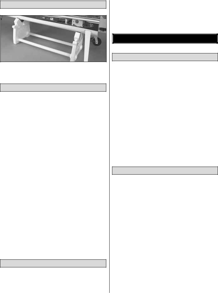
Building Stand
A building stand or cradle comes in handy during the build. We use the Robart Super Stand II (ROBP1402) for all our projects in R&D, and it can be seen in pictures throughout this manual.
Radio Equipment
Since the Yak 54 1.60 ARF is a large model capable of extreme aerobatics, standard servos should not be used to operate the control surfaces. Servos with a minimum torque rating of 98 oz-in [7.1 kg-cm] are required except for the throttle servo, which may be operated by a standard servo.
The following servo extensions and Y-harnesses were also used to build the Yak 54 1.60 ARF as shown in the manual.
•(2) 36" [910mm] servo extensions for elevator servos (HCAM2726 for Futaba J-connector)
•(2) 36" [910mm] servo extension for tail mounted rudder servos (HCAM2726 for Futaba J-connector)
•(2) 24" [610mm] servo extensions for aileron servos (HCAM2721 for Futaba J-connector)
•(2) 6" [150mm] servo extensions for forward mounted rudder servos (HCAM2701 for Futaba J-connector)
•(1) 12" [305mm] servo extension for throttle servo (HCAM2711 for Futaba J-connector)
Optional: (If using a radio system that does not support mixing of the elevator, rudder, and aileron servos, Y-harnesses will be required)
•(2) Hobbico® Pro HD Y-Harness (HCAM2751 for Futaba J-connector)
•(1) Reversing Y-Harness (for elevator servos)
•A battery pack with a minimum of 1500mAh should also be used. When flying large models such as this, ALWAYS check the battery condition before each flight.
Engine Recommendations
The recommended engine size range for the Yak 54 1.60 ARF is 1.5 to 1.8 cu in [25–30 cc] two-stroke glow engine, 1.8 to 2.1 cu in [30–36 cc] four-stroke glow engine, or 1.9 to 2.6 cu in [32–43 cc] gasoline engine. We recommend either
the O.S.® 1.60 FX glow engine (OSMG0661) or the FujiImvac™ BT-43 EI™ gasoline engine (FJIG0143). Both of these engines will allow the Yak 54 1.60 ARF to perform the 3D maneuvers it was designed for and the installations of both engines are covered in this manual. Do not install an engine larger than recommended!
ADDITIONAL ITEMS REQUIRED
Adhesives & Building Supplies
This is the list of Adhesives and Building Supplies that are required to finish the Yak 54.
Pro™ 30-minute epoxy (GPMR6047)
Pro 6-minute epoxy (GPMR6045)
1/2 oz. [15 g] Thin Pro CA (GPMR6001)
1/2 oz. [15 g] Medium Pro CA+ (GPMR6007)
Hobbico 60 watt soldering iron (HCAR0776)
Hobby Heat™ Micro Torch II (HCAR0755)
Silver solder w/flux (GPMR8070)
Petroleum jelly (Vaseline®)
3' [900 mm] Standard silicone fuel tubing (GPMQ4131)
R/C foam rubber (1/4" [6 mm] – HCAQ1000)
Microballoons (TOPR1090)
Drill bits: 1/16" [1.6 mm], 3/32" [2.4 mm], 7/64" [2.8 mm],
9/64" [3.6 mm], 5/32" [4 mm]
Denatured alcohol (for epoxy clean up)
8-32 Tap and drill set (GPMR8103)
#1 Hobby knife (HCAR0105)
#11 Blades (5-pack, HCAR0211)
Optional Supplies & Tools
Here is a list of optional tools mentioned in the manual and others items that will help you build the Yak 54 1.60 ARF.
Fuel filler valve for glow fuel (GPMQ4160)
Fuel filler valve for gasoline (GPMQ4161)
1/2 oz. [15 g] Thick Pro CA- (GPMR6013)
Milled fiberglass (GPMR6165)
Tap handle (GPMR8120)
Stick-on segmented lead weights (GPMQ4485)
Large scale single-sided servo arm (GPMM1100)
Epoxy brushes (6, GPMR8060)
Mixing sticks (50, GPMR8055)
Mixing cups (GPMR8056)
Builder’s Triangle Set (HCAR0480)
36" Metal ruler (HCAR0475)
Pliers with wire cutter (HCAR0630)
Hobbico Duster™ can of compressed air (HCAR5500)
Masking tape (TOPR8018)
Panel Line Pen (TOPQ2510)
Rotary tool such as Dremel®
Rotary tool reinforced cut-off wheel (GPMR8200)
Servo horn drill (HCAR0698)
Dead Center™ Engine Mount Hole Locator (GPMR8130)
4
CG Machine™ (GPMR2400)
#64 Rubber bands (1/4 lb [113 g] box, HCAQ2020)
Semi-Flexible Pushrod System (GPMQ3714)
IMPORTANT BUILDING NOTES
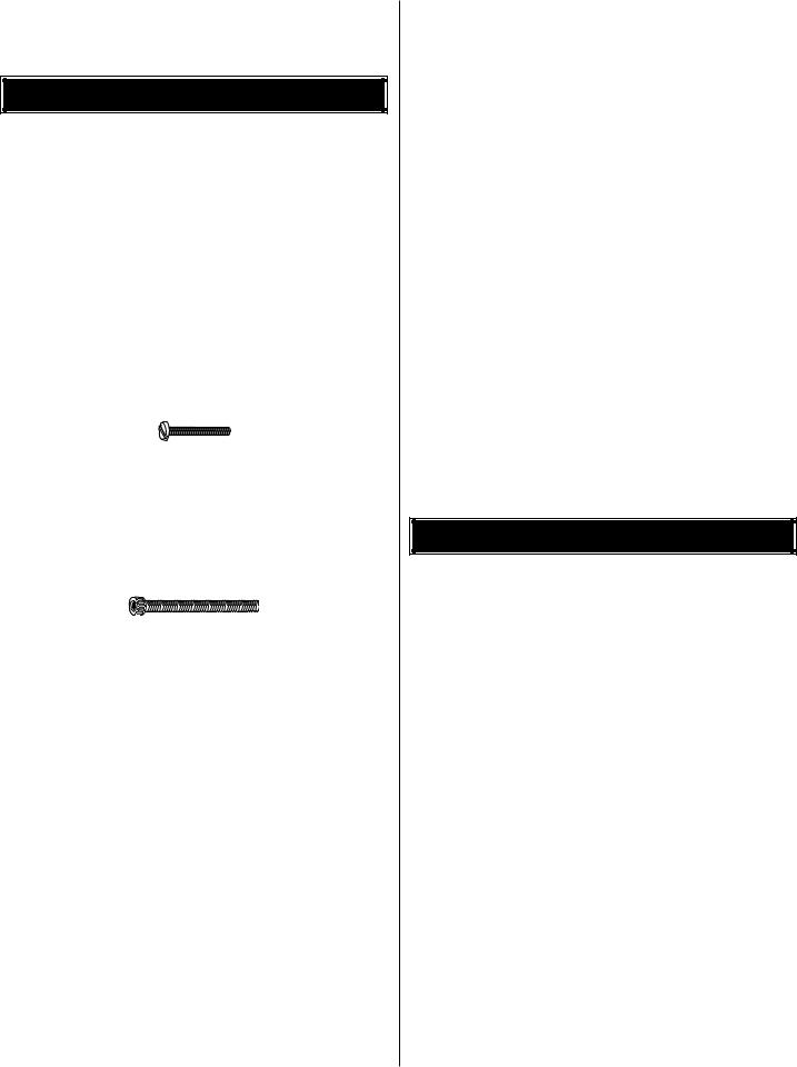
•There are two types of screws used in this kit:
•Sheet metal screws (SMS) are designated by a number and a length. For example #6 x 3/4" [19 mm]
This is a number six screw that is 3/4" [19 mm] long.
•Machine screws (MS) are designated by a number, threads per inch, and a length. For example 4-40 x 3/4" [19 mm].
This is a number four screw that is 3/4" [19 mm] long with forty threads per inch.
•Socket head cap screws (SHCS) are designated by a number, threads per inch, and a length. For example 4-40 x 1-1/2" [38 mm]
This is a number four screw that is 1-1/2" [38 mm] long with forty threads per inch.
•When you see the term test fit in the instructions, it means that you should first position the part on the assembly without using any glue, then slightly modify or custom fit the part as necessary for the best fit.
•Whenever the term glue is written, you should rely upon your experience to decide what type of glue to use. When a specific type of adhesive works best for that step, the instructions will make a recommendation.
•Whenever just epoxy is specified, you may use either 30-minute (or 45-minute) epoxy or 6-minute epoxy. When 30-minute epoxy is specified, it is highly recommended that you use only 30-minute (or 45-minute) epoxy, because you will need the working time and/or the additional strength.
•Photos and sketches are placed before the step they refer to. Frequently you can study photos in following steps to get another view of the same parts.
•The Yak 54 is factory-covered with Top Flite® MonoKote® film. Should repairs ever be required, MonoKote can be
patched with additional MonoKote purchased separately. MonoKote is packaged in six-foot rolls, but some hobby shops also sell it by the foot. If only a small piece of MonoKote is needed for a minor patch, perhaps a fellow modeler would give you some. MonoKote is applied with a model airplane covering iron, but in an emergency a regular iron could be used. A roll of MonoKote includes full instructions for application. Following are the colors used on this model and order numbers for six foot rolls.
Metallic Blue – TOPQ0402
Metallic Red – TOPQ0405
White – TOPQ0204
• The stabilizer and wing incidences and engine thrust angles have been factory-built into this model. However, some technically-minded modelers may wish to check these measurements anyway. To view this information visit the web site at www.greatplanes.com and click on “Technical Data.” Due to manufacturing tolerances which will have little or no effect on the way your model will fly, please expect slight deviations between your model and the published values.
ORDERING REPLACEMENT PARTS
Replacement parts for the Great Planes Yak 54 ARF are available using the order numbers in the Replacement Parts List that follows. The fastest, most economical service can be provided by your hobby dealer or mail-order company.
To locate a hobby dealer, visit the Hobbico web site at www.hobbico.com. Choose “Where to Buy” at the bottom of the menu on the left side of the page. Follow the instructions provided on the page to locate a U.S., Canadian or International dealer.
Parts may also be ordered directly from Hobby Services by calling (217) 398-0007, or via facsimile at (217) 398-7721, but full retail prices and shipping and handling charges will apply. Illinois and Nevada residents will also be charged sales tax. If ordering via fax, include a Visa® or MasterCard® number and expiration date for payment.
Mail parts orders and payments by personal check to:
Hobby Services
3002 N. Apollo Drive, Suite 1
Champaign, IL 61822
Be certain to specify the order number exactly as listed in the Replacement Parts List. Payment by credit card or personal check only; no C.O.D.
5
If additional assistance is required for any reason contact Product Support by e-mail at productsupport@greatplanes.com, or by telephone at (217) 398-8970.
Replacement Parts List
Order Number |
Description |
How to Purchase |
|
Missing pieces |
Contact Product Support |
|
Instruction manual |
Contact Product Support |
|
Full-size plans |
Not available |
GPMA2871 |
Wing Kit |
Contact Hobby Supplier |
GPMA2872 |
Fuse Kit |
Contact Hobby Supplier |
GPMA2873 |
Tail Set |
Contact Hobby Supplier |
GPMA2874 |
Cowl |
Contact Hobby Supplier |
GPMA2875 |
Canopy |
Contact Hobby Supplier |
GPMA2876 |
Landing Gear |
Contact Hobby Supplier |
GPMA2877 |
Wheel Spats |
Contact Hobby Supplier |
GPMA2878 |
Tail Wheel Assembly |
Contact Hobby Supplier |
GPMA2879 |
Decal Sheet |
Contact Hobby Supplier |
COMMON ABBREVIATIONS
Fuse = Fuselage
Stab = Horizontal Stabilizer Fin = Vertical Fin
LE = Leading Edge
TE = Trailing Edge
LG = Landing Gear Ply = Plywood
" = Inches mm = Millimeters
METRIC CONVERSIONS
1" = 25.4 mm (conversion factor)
1/64" |
= |
.4 mm |
3/4" |
= |
19.0 mm |
1/32" |
= |
.8 mm |
1" |
= |
25.4 mm |
1/16" |
= |
1.6 mm |
2" |
= |
50.8 mm |
3/32" |
= |
2.4 mm |
3" |
= |
76.2 mm |
1/8" |
= |
3.2 mm |
6" |
= 152.4 mm |
|
5/32" |
= |
4.0 mm |
12" |
= 304.8 mm |
|
3/16" |
= |
4.8 mm |
18" |
= 457.2 mm |
|
1/4" |
= |
6.4 mm |
21" |
= 533.4 mm |
|
3/8" |
= |
9.5 mm |
24" |
= 609.6 mm |
|
1/2" |
= |
12.7 mm |
30" |
= 762.0 mm |
|
5/8" |
= |
15.9 mm |
36" |
= 914.4 mm |
|
6
KIT INSPECTION
Before starting to build, take an inventory of this kit to make sure it is complete, and inspect the parts to make sure they are of acceptable quality. If any parts are missing or are not of acceptable quality, or if you need assistance with assembly, contact Product Support. When reporting defective or missing parts, use the part names exactly as they are written in the Kit Contents list.
Great Planes Product Support
3002 N. Apollo Drive, Suite 1
Champaign, IL 61822 Telephone: (217) 398-8970, ext. 5 Fax: (217) 398-7721
E-mail: airsupport@greatplanes.com
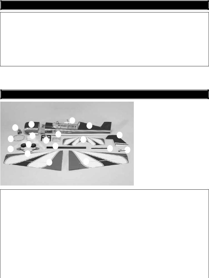
KIT CONTENTS
|
|
|
|
|
|
|
|
|
|
|
|
|
|
|
|
|
|
|
|
|
|
|
|
|
|
|
|
|
|
|
Kit Contents |
|
|
|
|
|
|
|
|
|
|
|
|
|
|
|
|
|
|
|
|
|
|
|
|
|
|
|
|
|
|
1. |
Aluminum Spinner |
|
|
|
|
|
|
|
|
|
|
|
|
|
|
|
|
|
|
|
|
|
|
|
|
|
|
|
|
|
|
2. |
Cowl |
|
|
|
|
|
|
|
|
|
|
|
|
|
|
|
|
|
|
|
|
|
|
|
|
|
|
|
|
|
|
3. |
Canopy |
|
|
|
|
|
|
|
|
|
|
|
|
|
|
|
|
3 |
|
|
|
|
|
|
|
|
|
|
|
|
|||
|
|
|
|
|
|
|
|
|
|
|
|
|
|
|
|
|
|
|
|
|
|
|
|
|
|
|
|
|
4. |
Fuselage |
|
|
|
|
|
|
|
2 |
|
|
|
|
|
|
|
|
|
|
|
|
|
|
|
|
|
|
|
|
|
||||
|
|
|
|
|
|
|
|
|
|
|
|
|
|
|
|
|
|
4 |
|
|
|
|
|
|
|
|
|||||
|
|
1 |
|
|
|
|
|
|
|
|
|
|
|
|
|
|
|
|
|
|
|
|
|
|
5. |
Cowl Ring |
|||||
|
|
|
|
|
|
|
|
|
|
|
|
|
|
|
|
|
|
|
|
|
|
|
|
|
|
||||||
|
|
|
|
|
|
|
|
|
|
|
|
|
|
|
|
|
|
|
|
|
|
|
|
|
|
|
|
6. |
Fuel Tank |
||
|
|
|
|
|
|
|
|
|
|
|
|
|
|
|
|
|
|
|
|
|
|
|
|
|
|
|
|
|
|
||
|
|
|
|
|
|
|
|
|
|
|
|
|
11 |
|
|
|
|
|
|
|
|
|
|
|
|
|
|
||||
|
|
|
|
6 |
|
|
|
|
|
|
|
|
|
|
|
|
|
|
|
|
|
|
|
7. |
Main Wheels (2) |
||||||
|
|
|
|
|
|
|
|
|
|
|
|
|
|
|
|
|
|
|
|
||||||||||||
|
5 |
|
|
|
|
|
|
|
|
|
|
|
|
|
|
|
|
|
|
|
|
|
|
|
|
|
|
|
|
|
|
|
|
|
|
|
|
|
|
|
|
|
|
|
|
|
|
|
|
|
|
|
|
|
|
|
|
|
|
|
|
||
|
|
|
7 |
|
|
|
|
|
|
|
|
|
|
|
|
|
|
|
|
|
|
|
|
|
|
|
|
|
|||
|
|
|
|
|
|
|
|
|
|
12 |
|
|
|
|
|
|
|
|
|
|
|
|
|
|
|
|
10. |
Engine Mount (L&R) |
|||
|
|
|
|
|
|
|
|
|
|
|
|
|
|
|
|
|
|
|
14 |
|
|
|
|
|
|
||||||
|
|
|
|
|
|
|
|
|
|
|
|
|
|
|
|
|
|
|
|
|
|
16 |
|
|
|||||||
|
|
|
|
|
|
|
|
|
|
|
|
|
|
|
|
|
|
|
|
|
|
||||||||||
|
|
|
|
|
8 |
|
|
|
|
|
|
|
|
|
|
|
|
|
|
|
|
|
|
|
|
|
|
|
11. |
Aft Receiver/Battery Tray |
|
|
|
|
|
|
|
|
|
|
|
|
|
|
|
|
|
|
|
|
|
|
|
|
|
|
|
|
|
|
|||
|
|
|
|
|
|
|
|
|
|
|
|
|
|
|
|
|
|
|
|
|
|
|
|
|
12. |
Aluminum Wing Tube |
|||||
|
|
|
|
|
|
|
|
|
|
|
|
|
|
|
|
|
|
|
|
|
|
|
|
|
|
|
|
|
|
||
|
|
|
|
|
|
|
|
|
|
17 |
|
|
|
|
|
|
|
|
|
|
|
|
|
|
|
|
|
|
13. |
Horizontal Stabilizer & Elevators |
|
|
|
|
|
|
|
|
|
|
|
|
|
|
|
|
|
|
|
|
|
|
|
|
|
|
|
|
|
14. |
Hook & Loop Material |
||
|
|
|
|
|
|
|
|
|
|
|
|
|
|
|
|
|
|
|
|
|
|
|
|
|
|
|
|
|
|
||
|
|
|
|
|
|
|
|
|
|
|
|
|
|
|
|
|
|
|
|
|
|
|
|
|
|
|
|
|
|
15. |
Rudder |
|
|
|
|
|
|
|
|
|
|
|
|
|
|
|
|
|
|
|
|
|
|
|
|
|
|
|
|
|
|
16. |
Tailwheel Assembly |
|
|
|
|
|
|
|
|
|
|
|
|
|
|
|
|
|
|
|
|
|
|
|
|
|
|
|
|
|
|
17. |
Left Wing Panel & Aileron |
|
|
|
|
|
|
|
|
|
|
|
|
|
|
|
|
|
|
|
|
|
|
|
|
|
|
|
|
|
|
18. |
Right Wing Panel & Aileron |
|
|
|
|
|
|
|
|
|
|
|
|
|
|
|
|
|
|
|
|
|
|
|
|
|
|
|
|
|
|
|
|
Kit Contents (not photographed)
(8) |
4-40 Steel Threaded Clevis |
(5) |
4-40 x 1/4" [6 mm] SHCS (for screw- |
(6) |
#6 Lock Washers |
(6) |
Solder Clevis |
|
lock pushrod connectors) |
(19) Hinge Points |
|
(2) |
3/16" [4.8 mm] Axles |
(6) |
6-32 x 5/8" [16 mm] SHCS |
(4) |
5/16" [8 mm] Anti-Rotation Pins |
(1) |
Screw-Lock Pushrod Connector |
(4) |
4-40 x 1" [25 mm] SHCS |
(2) |
Long Tie-Straps |
|
(for throttle pushrod) |
(10) |
4-40 x 1/2" [13 mm] SHCS |
(10) Cowl Alignment Disks |
|
(4) |
Heavy-Duty Screw-Lock Pushrod |
(4) |
8-32 x 1-1/4" [32 mm] SHCS |
(1) |
Throttle Servo Tray |
|
Connector (for rudder servos) |
(4) |
8-32 x 1" [25 mm] SHCS |
(1) |
3/8"-24 Spinner Adapter |
(8) |
4-40 Hex Nuts |
(2) |
1/8" x 3" [3 x 76 mm] Heat-Shrink Tubing |
(1) |
5 x 54 mm Spinner Screw |
(6) |
6-32 Blind Nuts |
(6) |
3/8" x 3" [9.5 x 76 mm] Heat-Shrink |
(1) |
5 x 70 mm Spinner Screw |
(2) |
5/16" x 24 Lock Nuts |
|
Tubing |
(1) |
5 mm Nut |
(4) |
3/32" [2.4 mm] Push Nuts (retainers |
(4) |
3/16" [4.8 mm] Wheel Collars |
(2) |
1/4"-20 Nylon Wing Bolts |
|
for heavy-duty screw-lock connectors) |
(1) |
.074 x 12" [305 mm] Wire Threaded |
(2) |
Canopy Alignment Pegs |
(1) |
Nylon Clevis (for throttle pushrod) |
|
One End |
(1) |
Pull-Pull Rudder System (includes |
(6) |
Heavy-Duty Nylon Control Horn |
(6) |
4-40 x 12" [305 mm] Wire Threaded |
|
pull-pull cable, brass couplers, |
(1) |
Retainer for Screw-Lock Pushrod |
|
One End |
|
swages, aluminum servo arm |
|
Connector |
(10) |
#4 Lock Washers |
|
extensions, and joiner rods |
(13) |
1/4" [6 mm] Clevis Retainers |
(10) |
#4 Flat Washers |
|
|
(8) |
2-56 x 3/8" [9.5 mm] Phillips Screw |
(8) |
#2 Flat Washers |
|
|
(4) |
6-32 x 1/4" [6 mm] SHCS |
(8) |
#8 Split Ring Lock Washers |
|
|
(24) |
#4 x 5/8" [16 mm] SMS |
(8) |
#8 Flat Washers |
|
|
|
|
|
|
|
|
|
|
|
7 |
|
|
PREPARATIONS
1. If you have not done so already, remove the major parts of the kit from the box and inspect for damage. If any parts are damaged or missing, contact Product Support at the address or telephone number listed in the “Kit Inspection” section on page 7.
2. Carefully remove the tape and separate all the control surfaces. Use a covering iron with a covering sock to tighten the covering if necessary. Apply pressure over sheeted areas to thoroughly bond the covering to the wood.
ASSEMBLE THE WING
Install the Ailerons
Do the left wing first so your work matches the photos the first time through. You can do one wing at a time, or work on them together.
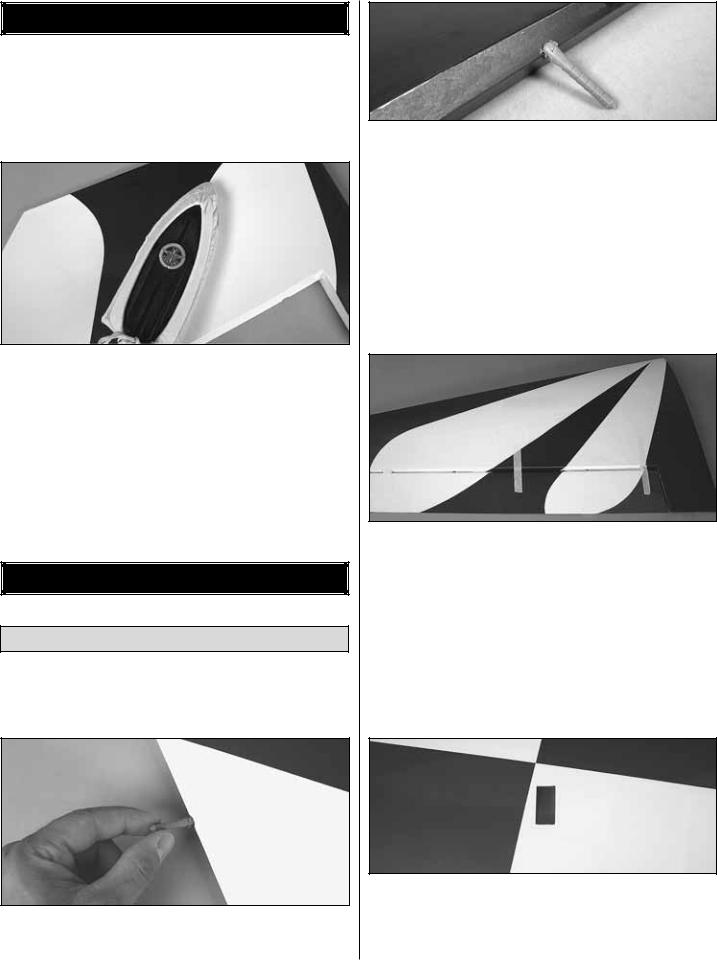
1. Test fit the included hinge points into the pre-drilled holes in the wing panel and aileron. Press the hinge points into the holes.
2. The hinge points should seat into the hinge holes all the way to the metal pin in order to minimize the gap between the aileron and wing. Use a hobby knife to enlarge the surface of the hinge holes as necessary until the proper fit is achieved. Test fit the aileron to the wing. The hinge gap between the aileron and wing should only be wide enough to allow a small line of light through. Excessive gap will decrease the effectiveness of the ailerons.
3. Apply a small amount of petroleum jelly or something similar to the center of each hinge to prevent epoxy from sticking to the joints and preventing the hinge from operating smoothly.
Read all of Step 4 before proceeding.
4. Mix up a 1/2 oz. [15 cc] of 30-minute epoxy. Using a toothpick or wood scrap, apply epoxy to the inside of each hinge point hole. The holes are drilled through to the open cavity in the wing, so be careful that you do not apply too much to the walls of the holes as it will simply drip into the wing. Apply a light coat of epoxy to one end of all the hinges for one wing panel. Insert the hinge points into the holes in the wing panel. Wipe away excess epoxy with a paper towel and denatured alcohol. Be sure the hinges are inserted in the correct orientation. Apply epoxy to the other ends of the hinges and slide the aileron into position. Use masking tape to hold the aileron in place while the epoxy cures.
5. Cut the covering 1/8" [3 mm] inside the opening in the wing for the aileron servo. Use a trim iron to seal the covering to the inner edges of the opening.
6. Repeat these steps for the right wing panel.
8
Install the Aileron Servos & Pushrods
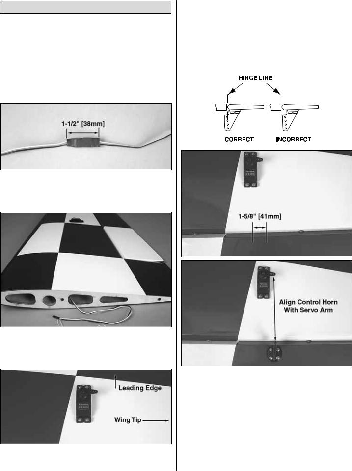
1. Installing the servos in the wing will require the use of one 24" [610 mm] servo extension for each aileron servo. One Y-harness connector is required and is used to allow the aileron servos to plug into one slot in your receiver. You may have a computer radio that allows you to plug the servos into separate slots and then mix them together through the radio transmitter. If you choose to mix them together with the radio rather than a Y-harness, refer to the manual with your particular model radio system.
2. Attach the 24" [610 mm] servo extension to the aileron servo and secure it with a piece of the included large heat-shrink tubing. Only 1-1/2" [38 mm] of heat-shrink tubing is required for each connector.
3. Tie the string from inside the opening for the aileron servo to the end of the servo extension. Remove the tape holding the other end of the string to the wing root rib and pull the servo wire and extension through the wing.
4. Temporarily position the aileron servo into the servo bay. Drill a 1/16" [1.6 mm] hole through the four mounting holes of the servo, drilling through the plywood mounting
plate in the wing. Install and remove a servo mounting screw into each of the four holes. Apply a drop of thin CA into the holes to harden the wood. After the glue has cured, install the servo into the opening using the hardware that came with your servo. Center the servo with your radio system and install a servo arm as shown.
The next three images are used for steps 5 and 6.
5.The aileron has a plywood plate for mounting the control horn. You can see the outline of it underneath the covering by looking at the aileron at a shallow angle. If you cannot see it, the plate is approximately 1-5/8" [41 mm] wide and will be centered with the servo arm. Use a T-pin to lightly puncture the covering to be sure you are over the plywood plate.
6. Place a heavy-duty nylon control horn on the aileron, positioning it over the hinge line as shown in the sketch and aligning it with the servo arm. Mark the location for the screw holes. Drill through the marks you made with a 3/32" [2.4 mm] drill bit. (Be sure you are drilling into the plywood plate mounted in the bottom of the aileron.) Drill through the plate only. Do not
9
drill all the way through the aileron!) Using a #4 x 5/8" [16 mm] sheet metal screw, install and then remove a screw into each of the holes. Harden the holes with thin CA. Install the control horn with four #4 x 5/8" [16 mm] sheet metal screws.
7. Locate a .095" x 12" [2.4 x 305 mm] pushrod wire threaded on one end. Thread a 4-40 nut, a silicone clevis retainer and a threaded metal clevis onto the threaded end of the wire 20 turns. Tighten the nut against the clevis and then install the clevis on the middle hole of the aileron control horn.
8. Be sure the aileron servo is centered. Install a 4-40 metal solder clevis onto the outer most hole in the servo arm. Center the servo arm and center the aileron. Using the solder clevis as a guide, mark where to cut the pushrod wire. Remove the pushrod and clevis from the control horn and the solder clevis from the servo arm. Cut the pushrod to length. Install another silicone clevis retainer onto the wire and solder the clevis to the pushrod using the Expert Tip that follows.
How to solder the clevis to the pushrod
1.Where the pushrod will make contact with the solder clevis, roughen the wire with 220-grit sandpaper.
2.Use a denatured alcohol to remove any oil residue from the wire pushrod.
3.Apply a couple of drops of flux to the wire. Slide the solder clevis onto the wire. Using a small torch or soldering iron, heat the wire, allowing the heated wire to heat the solder clevis. Apply a small amount of solder to the joint. When the wire and clevis are hot enough, the solder will flow into the joint. Avoid using too much solder, causing solder to flow out of the joint and clump. Use just enough solder to make a good joint. Allow the wire and clevis to cool.
4.Put a couple of drops of oil onto a rag and wipe the joint. This will prevent rust from forming on the joint.
9. Install the pushrod and clevises to the outer hole in the servo arm and the middle hole in the control horn. Adjust
the linkage until the aileron and the servo arm are both centered. Then, tighten the nut against the clevis. Slide the two silicone clevis retainers to the end of each clevis.
10. Repeat these steps for the right wing panel.
Finish the Wing
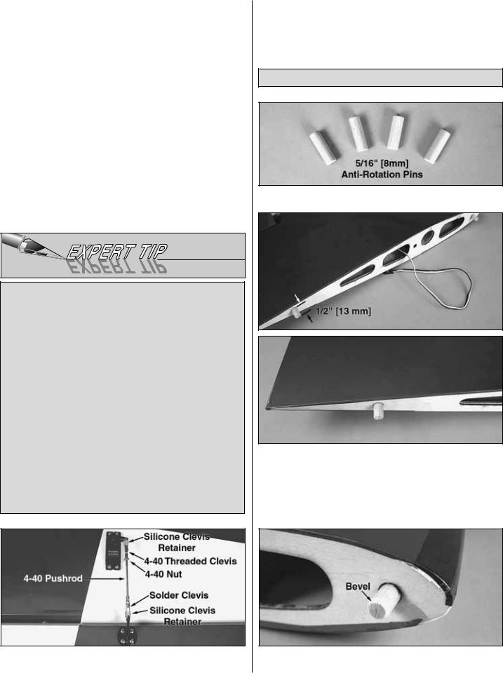
1. Locate the four 5/16" [8 mm] diameter anti-rotation pins.
2. Using 6-minute epoxy, coat half of the anti-rotation pins and insert them into the forward and aft holes in the wing panel root ribs. It may be necessary to carefully tap them into place. The pins should extend out approximately 1/2" [13 mm]. Wipe away any excess epoxy with a paper towel and denatured alcohol before the epoxy cures.
3. Use sandpaper to bevel the ends of the anti-rotation pins to ease their insertion into the fuselage.
10

ASSEMBLE THE FUSELAGE
Install the Rudder &Tail Gear
1. Trim the covering from the fuselage for the tail wheel bushing.
2. Apply CA or epoxy to the bushing and then, insert it into the hole by gently tapping it into place until fully seated. Be sure not to get glue into the hole in the bushing.
3. Just as you did with the ailerons, prepare the hinge point holes in the rudder and fuselage by test fitting the hinges and enlarging the holes as necessary.
4. Cut away 3/8" [10mm] from one end of the hinge that will be installed in between the small blue and red stripes (the hinge that is second from the bottom on the rudder). The end that has been cut should be the end that gets installed into the fuselage. Doing so will prevent this hinge from interfering with the installation of the horizontal stabilizer.
5. Mix up 1/4 oz. [7.5 cc] of 30-minute epoxy. Using a toothpick or wood scrap, apply epoxy to the inside of each hinge point hole. Apply a light coat of epoxy to one end of all the hinges for the rudder. Insert the hinge points into the holes, wiping away excess epoxy with a paper towel and denatured alcohol. Be sure the hinges are inserted in the correct orientation. Apply epoxy to the other ends of the hinges and slide the rudder into place. Use masking tape to hold the rudder in position while the epoxy cures.
6. Measure 1-1/2" [38 mm] back from the leading edge bevel of the rudder and make a mark on the underside center of the rudder.
7. Use a 5/32" [4 mm] drill bit to make a 1/2" [13 mm] deep hole at the mark. Insert the nylon retainer into the hole by tapping it gently, leaving 3/16" [4.8 mm] extending outside the hole. Align the hole to run parallel with the rudder.
11
 Loading...