


™
INSTRUCTION
MANUAL
SPECIFICATIONS
Wingspan: 59 in [1500mm] Radio:
Length: |
58 in [1475mm] |
Weight: |
6.5 – 7.25 lb [2950 – 3290 g] |
Wing Area: |
912 in2 [58.8 dm2] |
Wing Loading: |
16– 18 oz/ft2 [49– 55 g/dm2] |
4-channel minimum |
Engine: |
.55-.65 [9-10.5cc] |
with 5-6 servos |
|
two-stroke glow engine or .82 |
and standard size |
|
[13.5cc] four-stroke glow engine |
receiver |
Electric RimFire™ .80, (50-55-500) |
|
|
||
Power: Outrunner Brushless
WARRANTY
Great Planes® Model Manufacturing Co. guarantees this kit to be free from defects in both material and workmanship at the date of purchase. This warranty does not cover any component parts damaged by use or modification. In no case shall Great
Planes’ liability exceed the original cost of the purchased kit.
Further, Great Planes reserves the right to change or modify this warranty without notice.
In that Great Planes has no control over the final assembly or material used for final assembly, no liability shall be assumed nor accepted for any damage resulting from the use by the user of the final user-assembled product. By the act of using the user-assembled product, the user accepts all resulting liability.
If the buyer is not prepared to accept the liability associated with the use of this product, the buyer is advised to return
this kit immediately in new and unused condition to the place of purchase.
To make a warranty claim send the defective part or item to Hobby Services at the address below:
Hobby Services
3002 N. Apollo Dr. Suite 1
Champaign IL 61822 USA
Include a letter stating your name, return shipping address, as much contact information as possible (daytime telephone number, fax number, e-mail address), a detailed description of the problem and a photocopy of the purchase receipt. Upon receipt of the package the problem will be evaluated as quickly as possible.
READ THROUGH THIS MANUAL BEFORE STARTING CONSTRUCTION. IT CONTAINS IMPORTANT INSTRUCTIONS AND WARNINGS CONCERNING THE ASSEMBLY AND USE OF THIS MODEL.
Champaign, Illinois
(217) 398-8970, Ext 5 airsupport@greatplanes.com
Entire Contents © 2013 Hobbico,® Inc. All rights reserved. |
GPMA1272 Mnl |

TABLE OF CONTENTS
INTRODUCTION . . . . . . . . . . . . . . . . . . . . . . . . . . . . . . . . 2 Academy of Model Aeronautics . . . . . . . . . . . . . . . . . . 2 SAFETY PRECAUTIONS . . . . . . . . . . . . . . . . . . . . . . . . . 2 DECISIONS YOU MUST MAKE. . . . . . . . . . . . . . . . . . . . . 3 Radio Equipment . . . . . . . . . . . . . . . . . . . . . . . . . . . . . 3 Glow Engine Recommendations . . . . . . . . . . . . . . . . . 3 Brushless Motor Recommendations . . . . . . . . . . . . . . 4
ADDITIONAL ITEMS REQUIRED . . . . . . . . . . . . . . . . . . . 4 Required Hardware & Accessories . . . . . . . . . . . . . . . 4 Adhesives and Building Supplies. . . . . . . . . . . . . . . . . 4 Optional Supplies and Tools. . . . . . . . . . . . . . . . . . . . . 4 Building Stand . . . . . . . . . . . . . . . . . . . . . . . . . . . . . . . 5
IMPORTANT BUILDING NOTES. . . . . . . . . . . . . . . . . . . . 5
KIT INSPECTION. . . . . . . . . . . . . . . . . . . . . . . . . . . . . . . . 5
ORDERING REPLACEMENT PARTS . . . . . . . . . . . . . . . . 5
KIT CONTENTS. . . . . . . . . . . . . . . . . . . . . . . . . . . . . . . . . 6 PREPARATIONS . . . . . . . . . . . . . . . . . . . . . . . . . . . . . . . . 6
INSTALL THE AILERON SERVOS,
PUSHRODS AND BELLY PAN . . . . . . . . . . . . . . . . . . . 6 INSTALL THE TAIL SECTION . . . . . . . . . . . . . . . . . . . . . 10
INSTALL THE MAIN LANDING GEAR . . . . . . . . . . . . . . 12 INSTALL THE POWER SYSTEM. . . . . . . . . . . . . . . . . . . 13 Brushless Motor . . . . . . . . . . . . . . . . . . . . . . . . . . . . . 13 Glow Engine. . . . . . . . . . . . . . . . . . . . . . . . . . . . . . . . 16
INSTALL THE RECEIVER, BATTERY, AND SWITCH. . . 20
FINISH THE MODEL . . . . . . . . . . . . . . . . . . . . . . . . . . . . 21
INTRODUCTION
The U-Can-Do SF has the impressive fl ight characteristics of the original version with a refi ned design to speed up assembly, a fresh appearance with a new trim scheme, and now the provisions for a brushless setup. Like all of the latest Great Planes ARFs, many of the tasks typically required to be done during assembly have already been completed for you at the factory including pre-hinged ailerons and rudder, pre-glued canopy, and trimmed covering.
For the latest technical updates or manual corrections to the Great Planes U-Can-Do SF ARF visit the Great Planes web site at www.greatplanes.com. Open the “Airplanes” link, then select the U-Can-Do SF ARF. If there is new technical information or changes to this model a “tech notice” box will appear in the upper left corner of the page.
Academy of Model Aeronautics
We urge you to join the AMA (Academy of Model Aeronautics) and a local R/C club. The AMA is the governing body of model aviation and membership is required to fl y at AMA clubs. Though joining the AMA provides many benefi ts, one of the primary reasons to join is liability protection. Coverage is not limited to flying at contests or on the club fi eld. It even applies to fl ying at public demonstrations and air shows. Failure to comply with the Safety Code (excerpts printed in the back of the manual) may endanger insurance coverage. Additionally, training programs and instructors are available at AMA club
Optional Side Force Generators . . . . . . . . . . . . . . . . 24
Apply the Decals . . . . . . . . . . . . . . . . . . . . . . . . . . . . 24
GET THE MODEL READY TO FLY . . . . . . . . . . . . . . . . . 24
Check the Control Directions . . . . . . . . . . . . . . . . . . . 24
Set the Control Throws. . . . . . . . . . . . . . . . . . . . . . . . 25
Proper Pushrod Hookup; Avoiding Flutter,
Maximizing Servo Output Torque . . . . . . . . . . . . . 26
Balance the Model (C.G.). . . . . . . . . . . . . . . . . . . . . . 27
Balance the Model Laterally. . . . . . . . . . . . . . . . . . . . 27
PREFLIGHT . . . . . . . . . . . . . . . . . . . . . . . . . . . . . . . . . . . 27
Identify Your Model. . . . . . . . . . . . . . . . . . . . . . . . . . . 27
Charge the Batteries . . . . . . . . . . . . . . . . . . . . . . . . . 27
Balance Propellers. . . . . . . . . . . . . . . . . . . . . . . . . . . 28
Ground Check . . . . . . . . . . . . . . . . . . . . . . . . . . . . . . 28
Range Check . . . . . . . . . . . . . . . . . . . . . . . . . . . . . . . 28
ENGINE SAFETY PRECAUTIONS . . . . . . . . . . . . . . . . . 28
AMA SAFETY CODE. . . . . . . . . . . . . . . . . . . . . . . . . . . . 28
General . . . . . . . . . . . . . . . . . . . . . . . . . . . . . . . . . . . 28
Radio Control . . . . . . . . . . . . . . . . . . . . . . . . . . . . . . . 29
CHECK LIST . . . . . . . . . . . . . . . . . . . . . . . . . . . . . . . . . . 29
FLYING. . . . . . . . . . . . . . . . . . . . . . . . . . . . . . . . . . . . . . . 29
Fuel Mixture Adjustments . . . . . . . . . . . . . . . . . . . . . 29
Takeoff . . . . . . . . . . . . . . . . . . . . . . . . . . . . . . . . . . . . 30
Flight . . . . . . . . . . . . . . . . . . . . . . . . . . . . . . . . . . . . . 30
Landing . . . . . . . . . . . . . . . . . . . . . . . . . . . . . . . . . . . 30
3D Flying . . . . . . . . . . . . . . . . . . . . . . . . . . . . . . . . . . 30
sites to help you get started the right way. There are over 2,500 AMA chartered clubs across the country. Contact the AMA at the address or toll-free phone number below:
Academy of Model Aeronautics
5151 East Memorial Drive
Muncie, IN 47302-9252
Tele. (800) 435-9262
Fax (765) 741-0057
Or via the Internet at: http://www.modelaircraft.org
IMPORTANT!!! Two of the most important things you can do to preserve the radio controlled aircraft hobby are to avoid fl ying near full-scale aircraft and avoid fl ying near or over groups of people.
SAFETY PRECAUTIONS
Protect Your Model,Yourself & Others…
Follow These Important Safety Precautions
1. Your U-Can-Do SF ARF should not be considered a toy, but rather a sophisticated, working model that functions very much like a full-size airplane. Because of its performance capabilities, the U-Can-Do SF, if not assembled and operated correctly, could possibly cause injury to yourself or spectators and damage to property.
2

2.You must assemble the model according to the instructions. Do not alter or modify the model, as doing so may result in an unsafe or unfl yable model. In a few cases the instructions may differ slightly from the photos. In those instances the written instructions should be considered as correct.
3.You must take time to build straight, true and strong.
4.You must use an R/C radio system that is in fi rst-class condition, and a correctly sized engine and components (fuel tank, wheels, etc.) throughout the building process.
5.You must correctly install all R/C and other components so that the model operates correctly on the ground and in the air.
6.You must check the operation of the model before every fl ight to ensure that all equipment is operating and that the model has remained structurally sound. Be sure to check clevises or other connectors often and replace them if they show any signs of wear or fatigue.
7.If you are not an experienced pilot or have not flown this type of model before, we recommend that you get the assistance of an experienced pilot in your R/C club for your first fl ights. If you’re not a member of a club, your local hobby shop has information about clubs in your area whose membership includes experienced pilots.
8.While this kit has been fl ight tested to exceed normal use, if the plane will be used for extremely high stress fl ying, such as racing, or if an engine larger than one in the recommended range is used, the modeler is responsible for taking steps to reinforce the high stress points and/or substituting hardware more suitable for the increased stress.
9.WARNING: The cowl and wheel pants included in this kit are made of fi berglass, the fi bers of which may cause eye, skin and respiratory tract irritation. Never blow into a part to remove fi berglass dust, as the dust will blow back into your eyes. Always wear safety goggles, a particle mask and rubber gloves when grinding, drilling and sanding fi berglass parts. Vacuum the parts and the work area thoroughly after working with fi berglass parts.
We, as the kit manufacturer, provide you with a top quality, thoroughly tested kit and instructions, but ultimately the quality and flyability of your finished model depends on how you build it; therefore, we cannot in any way guarantee the performance of your completed model, and no representations are expressed or implied as to the performance or safety of your completed model.
REMEMBER: Take your time and follow the instructions to end up with a well-built model that is straight and true.
DECISIONS YOU MUST MAKE
This is a partial list of items required to finish the U-Can-Do SF that may require planning or decision making before starting to build. Order numbers are provided in parentheses.
Radio Equipment
The U-Can-Do SF requires a minimum 4-channel radio system with a minimum of fi ve 72 oz.-in. [5.2 kg-cm] minimum torque
standard sized servos and an additional standard torque servo if you are installing a glow engine.
For maximum 3D performance, we recommend using digital servos with at least 72 oz.-in. [5.2 kg-cm] of torque.
In addition, two 12" [305mm] servo extensions are required for the aileron servos and three 24" [610mm] servo extensions are required for the tail servos. A 6" [152mm] servo extension is required for the ESC if you are installing a brushless motor. If you are using a radio system that does not support mixing functions, a Y-harness will also be required to connect the aileron servos to the receiver. You will also need a reversing Y-harness to reverse the rotation of one of the elevator servos in order for both elevator halves to move together in the same direction.
Recommended part numbers for the radio components are provided below:
Futaba S3010 Standard High-Torque BB Servo (FUTM0043)
Futaba S3050 Digital Standard High Torque BB MG Servo (FUTM0300)
Futaba S3004 Standard Ball Bearing Servo (FUTM0004)
Hobbico 6" Extension Futaba J (HCAM2000)
Hobbico 12" Extension Futaba J (HCAM2100)
Hobbico 24" Extension Futaba J (HCAM2200)
Futaba Dual Servo Extension 6" J (FUTM4130)
EMS Servo Reverser Futaba J (EMOM0027)
Ernst Charge Receptacle Futaba J FM (ERNM3001)
Futaba SWH13 Switch Harness & Charge Cord Mini J (FUTM4370)
Great Planes Heat Shrink Tubing 3/8x3" (3) (GPMM1060)
If you plan to install a brushless motor, the availability of space on the battery tray will limit you to a standard 4.8V receiver battery (larger batteries may fi t inside the fuselage but there are no provisions for mounting them). If you installed a glow engine, a standard 4.8V receiver battery or a high energy 6.6V LiFe battery can be used. The high energy density and 6.6V nominal voltage rating would be a good match for this 3D model. The installation of a LiFe battery is shown in the manual. A charger capable of safely charging a LiFe battery is also required. Recommended part numbers are provided:
Hobbico HydriMax NiMH 4-Cell 4.8V 2000mAh Flat AA Rx U (HCAM6321)
Hobbico LiFeSource LiFe 6.6V 2100mAh 10C Receiver U (HCAM6436)
Hobbico LiFeSource AC/DC Balancing Charger 1S3S (HCAM6375)
Glow Engine Recommendations
The recommended engine/motor size for the U-Can-Do SF is a .55 –.65 cu in [9 –10.5cc] two-stroke engine or .82 [13.5cc] four-stroke engine. Choose a propeller based on the engine
3

manufacturer’s recommendation. The order number for the recommended engine is provided below. If you plan to install the recommended O.S. engine, we found that the APC 13 x 6 propeller works well.
O.S. 65AX ABL w/Muffl er (OSMG0558)
APC 13x6 Sport Propeller (APCQ1306)
Brushless Motor Recommendations
If you are planning on using electric power, we recommend the RimFire .80 brushless motor and a 60A ESC. A 15x6 electric propeller is a good choice with the recommended motor. Many batteries will work as a flight battery. We suggest the 22.2V 3350mAh EON-X Flight Power pack. Part numbers are provided below:
Great Planes RimFire .80 50-55-500 Outrunner Brushless (GPMG4740)
Great Planes Silver Series 60A Brushless ESC High Volt (GPMM1850)
APC 15x6 Thin Electric Propeller (APCQ1505)
FlightPower LiPo EON-X 30 6S 22.2V 3350mAh 30C (FPWP6358)
It is recommended to make a battery lead extension if installing a brushless motor. Part numbers needed to make the extension are as follows:
W.S. Deans® Female Ultra Plug® w/Pigtail (WSDM3010)
W.S. Deans® Male Ultra Plug® (2) (WSDM1302)
If you need a charger for your flight battery, we suggest either the Triton EQ or Triton 2 EQ. Both are very versatile chargers that can charge virtually any hobby battery currently available.
Great Planes ElectriFly Triton EQ AC/DC Charger (GPMM3155)
Great Planes ElectriFly Triton2 EQ AC/DC Charger (GPMM3156)
ADDITIONAL ITEMS REQUIRED
Required Hardware & Accessories
This is the list of hardware and accessories required to fi nish the U-Can-Do SF. Order numbers are provided in parentheses:
R/C foam rubber 1/4" [6mm] (HCAQ1000)
3' [900mm] standard silicone fuel tubing (GPMQ4131) (glow engine only)
Adhesives and Building Supplies
This is the list of Adhesives and Building Supplies that are required to fi nish the U-Can-Do SF ARF:
1/2 oz. [15g] Thin Pro CA (GPMR6001)
Pro 6-minute or 30-minute epoxy (GPMR6045 or GPMR6047)
Threadlocker thread locking cement (GPMR6060)
Denatured alcohol (for epoxy clean up)
Drill bits: 1/16" [1.6 mm], 5/64" [2 mm], 3/32" [2.4mm], 1/8" [3.2 mm], 11/64" [4.4 mm]
Rotary tool with cutting bit
Great Planes Heat Shrink Tubing 3/8x3" (3) (GPMM1060)
Revell Premium Soft Handle Knife w/Blades (5) (RMXR6900)
Top Flite MonoKote sealing iron (TOPR2100)
Top Flite Hot Sock iron cover (TOPR2175)
Panel Line Pen (TOPQ2510)
Hobbico Steel T-Pins 1" (100) (HCAR5100)
Small clamps
Masking tape
Household oil
Optional Supplies and Tools
Here is a list of optional tools that will help you build the U-Can-Do SF ARF:
1/2 oz. [15g] Thick Pro CA- (GPMR6013)
1/2 oz. [15g] Medium Pro CA+ (GPMR6007)
2 oz. [57g] spray CA activator (GPMR6035)
4 oz. [113g] aerosol CA activator (GPMR6034)
CA applicator tips (HCAR3780)
CA debonder (GPMR6039)
Epoxy brushes 6, (GPMR8060)
Mixing sticks (GPMR8055)
Mixing cups (GPMR8056)
Pliers with wire cutter (HCAR0630)
T.A. Emerald Performance Duster Compressed Air (TAEC1060)
Servo horn drill (HCAR0698)
Hobby Heat micro torch II (HCAR0755)
Dead Center™ Engine Mount Hole Locator (GPMR8130)
DuraTrax Ultimate Body Reamer (DTXR1157)
Precision Magnetic Prop Balancer (TOPQ5700)
AccuThrow Defl ection Gauge (GPMR2405)
CG Machine (GPMR2400)
Hobbico Flexible 18" Ruler Stainless Steel (HCAR0460)
Top Flite MonoKote trim seal iron (TOPR2200)
Top Flite MonoKote heat gun (TOPR2000)
Hobbico Pin Vise 1/16 Collet w/6 Bits (HCAR0696)
Hobbico 8-Piece Ball Tip Hex L Wrench SAE (HCAR0520)
Hobbico 7-Piece Ball Tip Hex L Wrench Metric (HCAR0521)
Great Planes Clevis Installation Tool (GPMR8030)
Great Planes Precision Prop Reamer Standard (GPMQ5006)
Great Planes Precision Prop Reamer Metric (GPMQ5007)
4
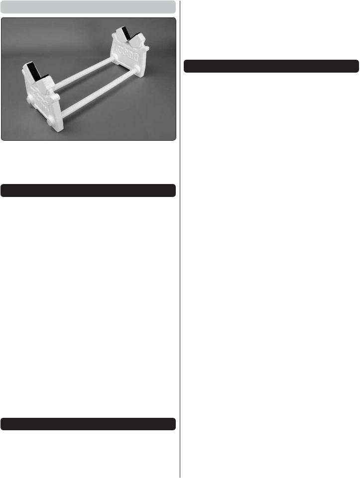
Building Stand
A building stand or cradle comes in handy during the build. We use the Robart Super Stand II (ROBP1402) for all our projects in R&D, and it can be seen in pictures throughout this manual.
IMPORTANT BUILDING NOTES
●When you see the term test fit in the instructions, it means that you should fi rst position the part on the assembly without using any glue, then slightly modify or custom fit the part as necessary for the best fi t.
●Whenever the term glue is written you should rely upon your experience to decide what type of glue to use. When a specifi c type of adhesive works best for that step, the instructions will make a recommendation.
●Whenever just epoxy is specifi ed you may use either 30-minute (or 45-minute) epoxy or 6-minute epoxy. When 30-minute epoxy is specified it is highly recommended that you use only 30-minute (or 45-minute) epoxy, because you will need the working time and/or the additional strength.
●Photos and sketches are placed before the step they refer to. Frequently you can study photos in following steps to get another view of the same parts.
●The stabilizer and wing incidences and engine thrust angles have been factory-built into this model. However, some technically-minded modelers may wish to check these measurements anyway. To view this information visit the web site at www.greatplanes.com and click on
“Technical Data.” Due to manufacturing tolerances which will have little or no effect on the way your model will fl y, please expect slight deviations between your model and the published values.
KIT INSPECTION
Before starting to build, take an inventory of this kit to make sure it is complete, and inspect the parts to make sure they are of acceptable quality. If any parts are missing or are not of acceptable quality, or if you need assistance with assembly, contact Product Support. When reporting defective
or missing parts, use the part names exactly as they are written in the Kit Contents list.
Great Planes Product Support |
|
3002 N Apollo Drive, Suite 1 |
Ph: (217) 398-8970, ext. 5 |
Champaign, IL 61822 |
Fax: (217) 398-7721 |
E-mail: airsupport@greatplanes.com
ORDERING REPLACEMENT PARTS
Replacement parts for the Great Planes U-Can-Do SF are available using the order numbers in the Replacement Parts List that follows. The fastest, most economical service can be provided by your hobby dealer or mail-order company.
To locate a hobby dealer, visit the Hobbico web site at www. hobbico.com. Choose “Where to Buy” at the bottom of the menu on the left side of the page. Follow the instructions provided on the page to locate a U.S., Canadian or International dealer.
Parts may also be ordered directly from Hobby Services by calling (217) 398-0007, or via facsimile at (217) 398-7721, but full retail prices and shipping and handling charges will apply. Illinois and Nevada residents will also be charged sales tax. If ordering via fax, include a Visa or MasterCard number and expiration date for payment.
Mail parts orders |
Hobby Services |
and payments by |
3002 N Apollo Drive, Suite 1 |
personal check to: |
Champaign IL 61822 |
Be certain to specify the order number exactly as listed in the Replacement Parts List. Payment by credit card or personal check only; no C.O.D.
If additional assistance is required for any reason contact Product Support by e-mail at productsupport@greatplanes. com, or by telephone at (217) 398-8970.
|
REPLACEMENT PARTS LIST |
|
|
Order No. |
Description |
GPMA4335 |
Fuselage |
|
|
GPMA4336 |
Wing / Ailerons |
GPMA4337 |
Horizontal Stabilizer / Elevators |
GPMA4338 |
Fin / Rudder |
GPMA4339 |
Cowl |
|
|
GPMA4340 |
Hatch |
GPMA4341 |
Landing Gear |
|
|
GPMA4342 |
Wheel Pants |
GPMA4343 |
Spinner |
GPMA4344 |
EP Motor Mount |
GPMA4345 |
Side Force Plates |
|
|
GPMA4346 |
Pushrods |
GPMA4347 |
Tail Wheel Assembly |
|
|
5
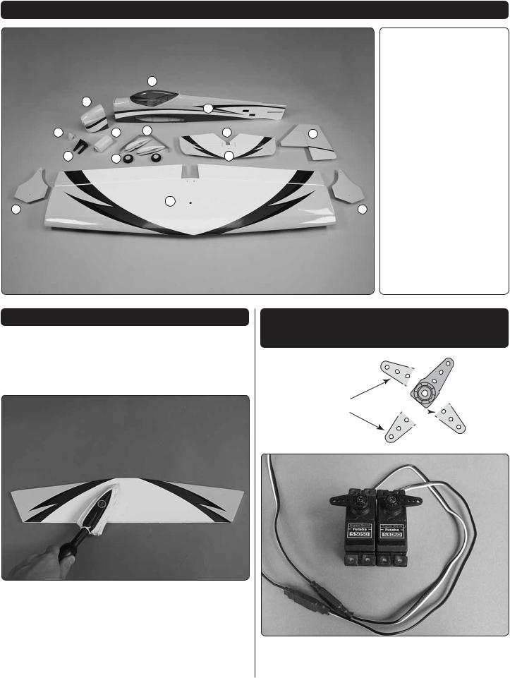
KIT CONTENTS
|
|
|
|
|
|
Kit Contents |
|
|
|
|
|
|
|
1. |
Cowl |
|
|
|
3 |
|
|
2. |
Fuselage |
|
|
1 |
|
|
|
3. |
Canopy Hatch |
|
|
|
2 |
|
|
|
|
|
|
|
|
|
4. |
Wing / Ailerons |
|
|
|
|
|
|
|
||
9 |
|
8 |
11 |
7 |
5 |
5. |
Vertical Fin / Rudder |
|
|
|
|
||||
|
|
|
|
|
|
6. |
Horizontal Stabilizer |
|
10 |
12 |
|
6 |
|
7. |
Elevator Halves |
|
|
|
|
|
|||
|
|
|
|
|
|
8. |
Fuel Tank |
|
|
|
|
4 |
|
9. |
Spinner |
13 |
|
|
|
13 |
10. |
Engine Mount |
|
|
|
|
|
||||
|
|
|
|
|
|
11. |
Landing Gear |
|
|
|
|
|
|
12. |
Wheels |
|
|
|
|
|
|
13. |
Side Force Generator |
PREPARATIONS
1. If you have not done so already, remove the major parts of the kit from the box and inspect for damage. If any parts are damaged or missing, contact Product Support at the address or telephone number listed in the “Kit Inspection” section on page 5.
2. Remove the tape and separate all the control surfaces. Use a covering iron with a covering sock on high heat to tighten the covering if necessary. Apply pressure over sheeted areas to thoroughly bond the covering to the wood.
INSTALL THE AILERON SERVOS, PUSHRODS AND BELLY PAN
CUT OFF
UNUSED 
ARMS
1. Center your aileron servos with your radio system. Test fi t four-armed servo arms onto the servos to determine their best orientation so that the arms are closest to being
6
perpendicular with the servo case. Cut three arms from each servo arm leaving one arm on each servo that matches the photo. Enlarge the outer hole of each remaining arm with a 5/64" [2mm] drill bit. Attach a 12" [305mm] servo extension to each servo. Secure the connection using tape, heat shrink tubing (not included) or special clips designed for that purpose. Install the rubber grommets and eyelets onto the servo mounting tabs.
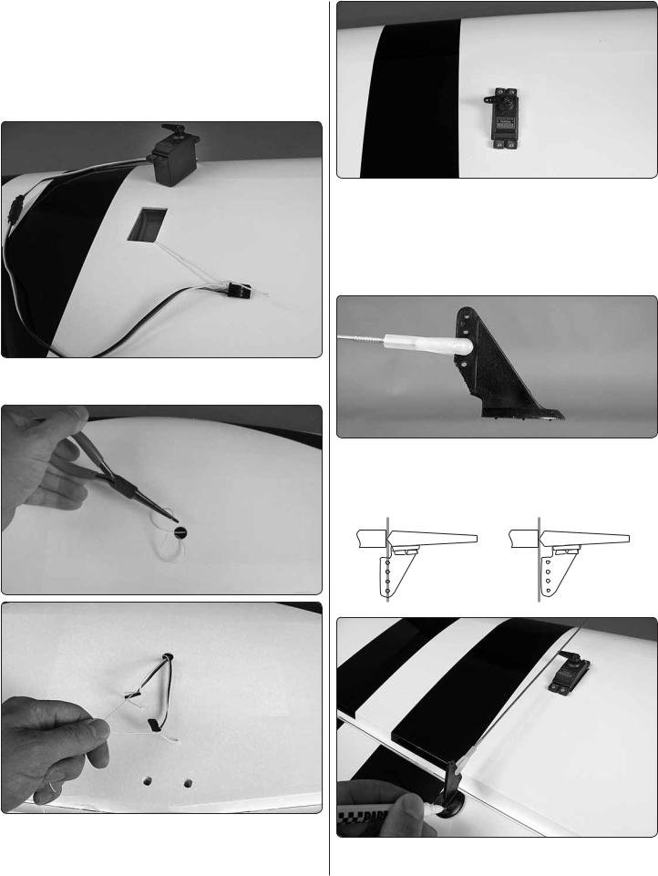
2. Tie the string ends that are taped inside the wings at the aileron servo bays to the servo extension connectors.
3. Reach into the hole in the center of the top of the wing with slender needle nose pliers and grab the string. Pull the string through the hole. Use the string to pull the servo leads through the wing and out the hole.
4. Fit the servos into the servo openings and drill 1/16" [1.6mm] holes through the mounting tabs on the servo cases into the rails. Thread a servo mounting screw (included with the servo) into each hole and back it out. Apply a drop of thin CA to each hole to harden the surrounding wood. When the CA has dried, install the servos into the openings as shown using the screws supplied with the servos.
5. Thread a nylon clevis onto two 12" [305mm] pushrods 20 complete turns. Attach each clevis to the middle hole of a large control horn. Cut off the bottom corner of each control horn.
Hinge Line |
Hinge Line |
Correct |
Incorrect |
6. Position a control horn onto the aileron aligning the pushrod with the outer hole of the aileron servo arm. Position
7
the control horns over the hardwood blocks in the ailerons (if you cannot see them, hold the aileron at a shallow angle in good lighting or use a small pin to puncture the covering). When satisfi ed, use a felt-tip pen to mark the location of the control horn mounting holes onto the aileron. Repeat this step for the other aileron.
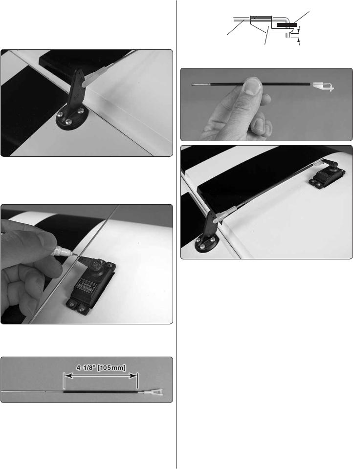
7. Drill 5/64" [2mm] holes at the marks you made. Thread a #4 x 5/8" [16mm] self-tapping screw into each hole and back it out. Apply a drop of thin CA to each hole to harden the surrounding wood. Install the control horns onto the ailerons using eight #4 x 5/8" [16mm] screws.
8. With the ailerons in the neutral position (use tape or small clamps to hold them in place), mark the pushrod wires where they cross the outer holes in the servo arms.
9. Clean the area of the pushrods between the marks you made and the threads with a paper towel dampened with denatured alcohol. Apply a thin coating of epoxy onto the pushrods from the end of the threads to approximately 3/4" [19mm] from your marks. Slide the two 4-1/8" [105mm] carbon tubes over the pushrods up to the pushrod threads. Wipe away any excess epoxy with denatured alcohol and allow the epoxy to cure undisturbed.
Servo Horn
Pushrod Wire
FasLink 1/16"[1.6mm]
10. Make a 90 degree bend at the mark on each pushrod and cut off the excess pushrod 1/4" [6mm] ends beyond the bends. Attach the pushrods to the servo arms using nylon FasLinks. Thread the clevises up or down on the pushrods as necessary to center the ailerons with the servo arms still perpendicular to the servo cases. When satisfied, slide silicone clevis retainers onto the ends of the clevises to secure them.
8
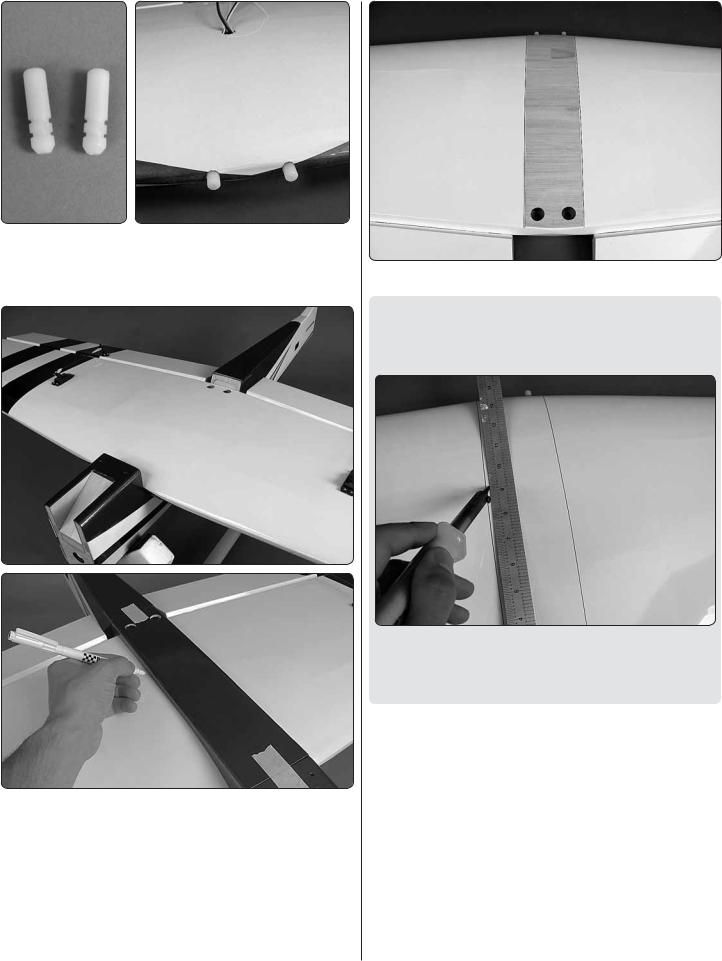
11. Locate the two nylon wing dowels. Coat the grooved ends with epoxy and fit the dowels into the holes at the leading edge of the wing as far as they will fi t into the holes. Wipe away any excess epoxy with denatured alcohol.
12. Mount the wing onto the fuselage using two 1/4-20 nylon wing bolts. Fit the belly pan onto the underside of the wing, align it with the fuselage and temporarily tape it into place. Use a felt-tip pen to trace around the belly pan onto the wing.
13. Remove the covering between the lines you drew.
HOW TO CUT COVERING FROM BALSA
Use a soldering iron to cut the covering from the stab. The tip of the soldering iron doesn’t have to be sharp, but a fine tip does work best. Allow the iron to heat fully.
Use a straightedge to guide the soldering iron at a rate that will just melt the covering and not burn into the wood. The hotter the soldering iron, the faster it must travel to melt a fine cut. Peel off the covering.
14. Use epoxy to glue the belly pan to the wing. Take care not to glue the belly pan to the fuselage. It is recommended to separate the forward and aft ends of the belly pan and fuselage with wax paper before gluing it in place.
9

INSTALL THE TAIL SECTION
C 
 D
D
C = D
1. Insert the horizontal stabilizer into the stabilizer slot and center it left and right. Align the stab so the distance between the wing tips and stab tips are equal on both sides. Now, with the wing still in place, stand behind the model approximately 10 feet [3m] and confi rm that the stab sits parallel with the wing. If not, weight can be added to to the high side while gluing the stab in place, or the stab pocket can be lightly sanded until the stab and wing sit parallel.
2. With the stab carefully aligned from the previous step, use a fi ne felt-tip pen to trace the outline of the fuselage onto the stab. Mark the top and bottom of the stab.
Pull the stab from the fuselage and remove the covering 1/16" [1.6mm] inside your lines using the same technique you used on the wing.
3. Coat the exposed wood with 30-minute epoxy (although messy, a more reliable glue joint can be attained if you also coat the inside edges of the stab pocket). Reinstall the stab and properly position it in the pocket. Wipe away any excess epoxy with denatured alcohol and let the epoxy cure undisturbed. When cured, the wing can be removed from the fuselage and set aside as it will not be needed until the fi nal set up of the plane.
4. Stick a T-pin or something simliar through the center of six CA hinges. Insert the hinges into the slots in the trailing edge of the stab up to the pins. Install the elevator halves onto the other ends of the hinges. Allow approximately 3/32" [2.4mm] gap between the ends of the stab and the elevators. Pull the pins out, deflect the elevator halves down and apply 6 to 7 drops of thin CA glue to the center of each hinge. Flip the plane over and apply another 6 or 7 drops to the undersides of the hinges. When the CA glue has dried, pull on each elevator half to confirm they are thoroughly glued in place.
10
 Loading...