


INSTRUCTIONS
READ THROUGH THIS INSTRUCTION BOOKLET IN ITS ENTIRETY BEFORE BEGINNING ASSEMBLY. IT CONTAINS IMPORTANT INSTRUCTIONS AND WARNINGS CONCERNING THE BUILDING AND USE OF THIS MODEL.
WARNING! THIS IS NOT A TOY!
The model you will build from this kit is not a toy! It is capable of serious bodily harm and property damage. IT IS YOUR RESPONSIBILITY AND YOURS ALONE -- to build this kit correctly, properly install all R/C components and to test the model and fly it only with experienced, competent help, using common sense and in accordance with all safety standards as set down in the Academy of Model Aeronautics Safety Code. It is suggested that you join the AMA and become properly insured before you attempt to fly this model. IF YOU ARE JUST STARTING R/C MODELING,
CONSULT YOUR LOCAL HOBBY SHOP OR WRITE TO THE ACADEMY OF MODEL AERONAUTICS TO FIND AN EXPERIENCED INSTRUCTOR IN YOUR AREA.
Academy of Model Aeronautics 5151 East Memorial Drive Muncie, IN 47302-9252
PO BOX 788 |
Urbana Illinois 61801 |
217/3988970 |

TABLE OF CONTENTS
Die Patterns .................... |
3 |
INTRODUCTION ............... |
4 |
Precautions ..................... |
4 |
Other Items Required ............. |
4 |
Optional Hop-up Items ............ |
5 |
Supplies and Tools Needed ......... |
5 |
A Word About Adhesives ........... |
5 |
Abbreviations ................... |
6 |
Types of Wood ................... |
6 |
Get Ready to Build ............... |
6 |
TAIL FEATHERS ............... |
6 |
Build the Fin and Rudder ........... |
6 |
Build the Stabilizer and Elevator ..... 7 |
|
Cut the Hinge Slots ............... |
8 |
WING ASSEMBLY .............. |
9 |
A Decision You Should Make Now . . . 9 |
|
Build the Inner Wing Panel ......... |
9 |
Build the Outer Wing Panel ......... |
13 |
Join the Inner and Outer Wing Panels |
. 15 |
Final Wing Assembly .............. |
16 |
FUSELAGE ASSEMBLY ......... |
19 |
Assemble Fuselage Sides . . . . . . . . . |
. . 19 |
Frame-up the Fuselage ............. |
20 |
Assemble the Canopy ............. |
22 |
Install the Motor ................. |
24 |
FINAL ASSEMBLY ............ . |
25 |
Balance the Airplane Laterally ....... |
25 |
Final Sanding . . . . . . . . . . . . . . . . |
. . . 25 |
Covering ....................... |
25 |
Checking for Warps .............. |
26 |
Glue the Hinges ................. |
26 |
Mount the Tail Surfaces ........... |
26 |
Assemble Pushrods ............... |
27 |
Install Radio Gear ................ |
27 |
Control Throws ................. . |
30 |
Final Hookups and Checks ......... |
30 |
Balance Your Model .............. |
31 |
PRE-FLIGHT ................. . |
31 |
Charge the Batteries .............. |
31 |
Find a Safe Place to Fly ........... |
31 |
Range Check Your Radio .......... |
32 |
Install the Wings ................. |
32 |
AMA Safety Code .............. |
. 32 |
General ........................ |
32 |
Radio Control ................... |
32 |
FLYING ...................... |
. 32 |
Hand Launched Trim Flights ........ |
32 |
Your First Flight ................. |
33 |
THERMAL FLYING ........... |
. 34 |
Facts About Thermals ............. |
34 |
Thermal Soaring ................ . |
34 |
Some Important Soaring Tips ....... |
35 |
Dynamic Braking Modification ...... |
35 |
PARTS LIST .................. . |
36 |
Please inspect all parts carefully before starting to build! If any parts are missing, broken or defective, or if you have any questions about building or flying this airplane, please call us at (217) 398-8970 and we'll be glad to help. If you are calling for replacement parts, please look up the part numbers and the kit identification number (stamped on the end of the carton) and have them ready when calling.
2

DIE PATTERNS
Do not punch out die-cut parts until you are ready to use them!
SPECFOl |
2 PER KIT |
BALSA 3/32 X 3 1/4 X 38 1/2
SPECF06 |
1 PER KIT |
SPECF02 |
2 PER KIT |
BALSA 1/8 X 3 X 8 7/8
BALSA 1/16 X 3 1/4 X 23 7/8
SPRTW07 |
2 PER K I T |
SPECF03 |
1 PER KIT |
BALSA 1/16 X 3 X 15
SPECF05 |
I PER KIT |
SPECF13 |
|
2 |
PER KIT |
BALSA |
1/16 X |
2 5/8 X |
II 7/6 |
SPECF07 |
1 PER KIT |
|
|
PLY 1/8 |
X 2 7/8 |
X 7 7/8 |
|
SPRTS01 |
|
I PER |
KIT |
BALSA 3/16" X 3" X 9-7/8"
SPRTW08 |
I PER KIT |
PLY 1/8 |
X 3 7/8 X |
I I 7/8 |
SPRTW05 |
NOT U S E 0 IN SPECW< KT |
I PER KIT |
PLY 1/8 |
X 3 X 19 |
SPRTF04 |
1 PER KIT |
BALSA 3/32 X 4 X 21
SPRTW02 |
2 PER KIT |
BALSA 1/16 |
X 3 X 23 7 / 8 |
SPRTW03 |
2 PER KIT |
BALSA 1/16 X 3 X 23 7/8
SPRTW01 |
I PER KIT |
BALSA 1/8 X 3 X 23 7/8
SPRTW04 |
1 PER KIT |
SPRTW06 |
I PER KIT |
PLY 1/16 |
X 3 3/8 X I I 7/8 |
PL Y 1/8 |
X 3 3/4 X 10 1/2 |
PL Y 1/32 |
X 3 1/4 |
X 9 3/4 |
3
INTRODUCTION
Congratulations! You are about to enter one of the most exciting realms of radio control flying - Electric Powered
Sailplanes.
Electric powered soaring is one of the most enjoyable types of R/C flying because it combines the convenience of being able to fly from almost any small field with the challenge of staying aloft for long periods of time. There is something very gratifying about defying gravity and being able to gain altitude using only nature's own air currents. The Spectra's powerful Goldfire motor quickly pulls it up to thermaling altitude where the motor is shut off and the Spectra becomes a "Thermaling Machine". With a little practice, you will be able to soar for hours in a single flight!
We would like to take this chance to thank you for purchasing the Great Planes SPECTRA Electric Sailplane. It has been designed to give you many hours ofenjoyable flight, and we spent many months engineering it to be a very enjoyable kit to build. If you have any comments or suggestions feel free to share them with us.
PRECAUTIONS
1.You must build the plane according to the plans and instructions. Do not alter or modify the model as doing so may result in an unsafe or un-flyable model. In a few cases the plans and instructions may differ slightly from the photos. In those instances you should assume the plans and written instructions are correct
2.You must take time to build straight, true and strong.
3.You must use a proper R/C radio that is in first class condition.
4.You must properly install all R/C and other components so that the model operates properly on the ground and in the air.
5.You must test the operation of the model before the first and each successive flight to insure that all equipment is operating, and you must make certain that the model has remained structurally sound. Be sure to check the nylon clevises often, and replace if they show signs of wear.
6.You mustfly the model only with the competent help of a well experienced R/C pilot if you are not already an experienced and knowledgeable R/C pilot at this time.
Note: We, as the kitmanufacturer, can provide you with a top quality kit and great instructions, but ultimately the quality and''fly-ability"ofyour finished model depends on how you build it; therefore, we cannot in any way guarantee the performance of your completed model, and no representations are expressed or implied as to the performance or safety of your completed model.
Remember: Take your time and follow directions to end up with a well-built model that is straight and true.
OTHER ITEMS REQUIRED
RADIO - A Radio having at least 2 channels is required to control the SPECTRA (a third channel is required for throttle control). Standard size servos can be used without any problem but a 250 mAh receiver battery is recommended but not required. Make sure that the radio is on an "Aircraft Only'' frequency.
FLIGHT BATTERY - A 6 or 7 cell battery with a " Kyosho" type connector is required to power the electric motor. We recommend you use a 7 cell battery as it offers much higher performance than a 6 cell battery. The capacity (mAh) of the battery can be anywhere from 800 mAh to 1700 mAh. For general flying a 1200 -1700 mAh 7 cell battery will provide good power, good motor duration, and good flight performance. For contest flying an 800 - 900 mAh 7 cell battery will provide a shorter motor duration but its lighter weight will enable the SPECTRA to climb quicker and soar better. A 1200 -1700 mAh 6 cell battery should be used ifyoujust want toflyaround with themotoroncontinuously. Ifyourbatteries have "Tamiya" style connectors, you'll have to change the connector on the wiring harness, or purchase a Kyosho #6195 adaptor.
CHARGER - A quick (15-20 Minute) charger is required to charge your flight battery. These chargers come in many different styles (DC, AC/DC, Timed, Peak, Temperature Sensing, etc.).
The most inexpensive charger will be a DC Quick Chargerwith a 15 - 30 minute timer. This type ofcharger will work fine but you should never leave the charger unattended while charging as the timers are not always reliable. If the timer sticks or the battery already had some charge in it, the battery could be over charged, heat up and explode. Ifyou use this type of charger, check the temperature of the battery every couple ofminutes and turn the charger offas soon as the battery starts getting warm.
The best type of chargers are the "Peak'' chargers. They constantly measure the voltage of the battery being charged and when the voltage starts to drop (as the voltage of a Nicad battery will do when it is fully charged) it will shut off. All
4
you have to do is connect the battery, push one button and come back when its done.
OTHER ITEMS:
Iron-on Covering Material-2 rolls (we recommend Monokote for the wing because of its superior strength)
Latex Foam Rubber Padding (1/4" thick)
#64 Rubber Bands
OPTIONAL HOP-UP ITEMS:
FOLDING PROP - A folding prop can be used instead ofthe 8 x 4 nylon prop supplied. It will fold back against the fuselage when the motor is not running and enhance the soaring performance of the plane. Sonictronics makes several nice folding props and we have found the model #174 8 x 4 folding prop to work well on the SPECTRA with the GOLDFIRE motor. The spinner may have to be carved out slightly to clear a folding prop. Because the prop may have a tendency to keep spinning after the motor is shut off, the switch/motor should probably be re-wired to provide dynamic braking to the motor. This is easy to do and will make the motor stop turning so the prop will fold back. There is a sketch on page 35 showing this wiring modification.
LIGHTWEIGHT RADIO - There are several "Micro Systems" on the market that come with smaller servos, receiver and batteries. Futaba makes a radio especially for electrics (model 4NBL Attack E) which works well with the SPECTRA. It comes with two S-133 Micro Servos and a 4 channel Receiver with a fully proportional electronic speed control built in. This unit also has BEC (Battery Eliminater Circuitry). This feature allows the radio system to be powered by the flight battery (6 or 7 cell). It will automatically shut the motor offbefore the battery is totally drained, leaving another 20 minutes or so of flying time in the flight battery. These smaller radio systems can save several ounces of valuable weight which will improve both the climbing and soaring capabilities of the plane.
COBALT MOTORS - A GOLDFIRE motor is included in this kit. It is a 550 size motor designed especially for airplanes. It is an inexpensive motor that is as powerful as many motors costing 3 times as much. We do notrecommend that you use any ofthe 540 size "Car'' motors. Their smaller size and higher RPM requirements do not work well when trying to turn a propeller at 12,000 rpm. If you want a higher performance motor, we recommend you use an Astro Fight
.05 Cobalt Motor (Model 6605 or 6605S). These motors are very powerful and will make your SPECTRA climb like crazy with some sacrifice in run time. We recommend that you use either Sermos Power Pole Connectors or Deans Connectors on the battery and motor when using high performance motors. These connectors have a very low resistance and will carry the larger currents better than the more popular connectors provided.
Your local hobby shop can be very helpful when deciding what types ofaccessories to purchase. We highly recommend that you consult with and support your local hobby dealer when purchasing the above items. He can also be a tremendous help if you have problems building or flying your models.
SUPPLIES AND TOOLS NEEDED
1 oz. Thin CA Adhesive
2 oz. Medium or Thick CA Adhesive (We'll refer to it as "thick" in theinstructions)
2.5 oz. 30-Minute Epoxy Hand or Electric Drill
Drill Bits: 1/16", 3/32", 1/8", 1/4" Sealing Iron
Heat Gun
Razor Saw
Hobby Knife, #11 Blades Pliers
Screw Drivers T-Pins
Assorted Rubber Bands Straightedge
Masking Tape
Sandpaper (coarse, medium, fine grit)* T-Bar Sanding Block (or similar) Waxed Paper
Lightweight Balsa Filler
Dremel Moto Tool or Similar (optional)
*NOTE: On our workbench, we have four 11" T-Bar sanders, equipped with #50, #80, #100 and #150-grit sandpaper. This setup is all that is required for almost any sanding task. We also keep some #320-grit wet-or-dry sandpaper handy for finish sanding by hand before covering.
A WORD ABOUT ADHESIVES
Ifyou looked at the "ITEMS NEEDED" list above, you probably noticed that we recommend only two basic types of glue for assembling the SPECTRA. . .CA adhesives and Epoxy adhesive. Glues have come a long way in the past few years and these two types of adhesive are all that is needed to build a strong and light structure.
CA (Cyanoacrylate) - These are the "Super Glues". They have revolutionized model building by eliminating the "wait for the glue to dry'' phase of building. CA'S will be used for 95% of the building. They come in several viscosities but we will only require the "Thin" (Runs like water) and the "Medium" (Like a thin syrup). The thin CA will be used where there is a nice tight fitting joint. It is applied after the
5
parts are in position and it seeps into the joint through capillary action and bonds the parts within a couple of seconds. The thickerCA is applied to the parts before they are joined and it takes up to 30 seconds to cure giving you a few seconds to position the parts. A related and very handy product is CA Accelerator Spray (Zip Kicker, etc.). This is used to instantly cure CA glues of all types.
EPOXY - Epoxy adhesives are two-part resins that are very strong but need to be mixed before they will cure. This process along with their heavier weight does not lend itself well to general construction. Epoxies are used where the utmost in strength is required. They come in many different cure times but we will only need 30 minute epoxy.
AN IMPORTANT TIP - Glue should never be substituted for a good-fitting joint. Take a little extra time to get a goodjoint and glue itproperly and it will be much stronger, much neater and much lighter than a bad joint held together with a glob of glue!
COMMON ABBREVIATIONS USED IN THIS BOOK AND ON THE PLANS:
Elev |
= |
Elevator |
Fuse |
= |
Fuselage |
LE |
= |
Leading Edge (front) |
Lt |
= |
Left |
Ply |
= |
Plywood |
Rt |
= |
Right |
Stab |
= |
Stabilizer |
TE |
= |
Trailing Edge (rear) |
Tri |
= |
Triangle |
"= Inches
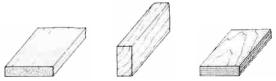
TYPES OF WOOD
BALSA |
B A S S W O O D |
PLYWOOD |
GET READY TO BUILD
NOTE: It will be helpful to build on a piece of "Celotex" (available from a lumber co.) or other semi-soft (and flat) surface, into which you may easily suckpins to firmly holddown the parts while building, and to avoid warps.
1. Unroll the plan sheet. Re-roll the plan inside out and let it uncurl while you read through this instruction book. This will help the plan lay flat and give you time to get acquainted with the building process. NOTE: Because there are several options to consider when building the SPECTRA, you should read the instruction book through before building and then go back and cross offthe steps you won't use to build your model.
2. Remove all parts from the box. As you do, figure out the name of each part by comparing it with the plans, the die patterns (p. 3) and the parts list at the back ofthis book. Write the part name or size on each piece to avoid confusion later. If any of the die-cut parts are difficult to punch out during construction, do not force them! Instead, first cut around the parts withahobbyknife. Afterpunchingoutthedie-cutparts, use your T-Bar or sanding block to lightly sand the edges to remove any die-cutting irregularities.
NOTICE: INSTRUCTIONS IN BOXES ARE VERY IMPORTANT AND SHOULD BE FOLLOWED CAREFULLY.
"TAIL FEATHERS"
BUILD THE FIN AND RUDDER
You'll need the following parts:
SPRTS02 |
3/16" x 3/8" x 30" Balsa Stick |
SPRTS03 |
1/8" x 3/16" x 30" Balsa Stick |
SPRTS01 |
3/16" Die-Cut Balsa Tail Parts |
SPECF08 |
3/16" Balsa Triangle |
D 1. Tape or pin the plan down to your flat work surface. Tape a piece of waxed paper over the fin and rudder portion of the plan (so you don't glue the parts to the plan).
6
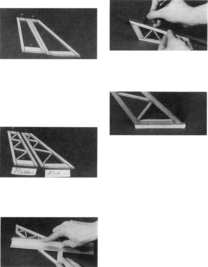
D 2. Using the plan as a guide, cut pieces of 3/16" x 3/8" balsa (from the 30" sticks, SPRTS02) to make the Rudder and Fin Framework. NOTE: Cut the Fin L.E, the Rudder L.E. and the Rudder T.E. from a single SPRTS02 (this will leave enough long pieces for the stab frame). Punch out the die-cut Fin Tip, Rudder Tip, Fin Base and Rudder Base from SPRTS01. Sand any rough edges on these pieces and then pin them in place on the plan. Glue the parts together using thin CA glue. CAUTION: Do not glue the fin to the rudder!
D 3. From the 1/8" x 3/16" x 30" sticks (SPRTS03), cut the diagonal "ribs" to fit between the rudder and fin framework, and glue them in place. NOTE: It is not necessary to get these ribs in the exact position shown on the plan.
D 4. Remove the fin and rudder assemblies from the plan and examine them for any open or bad joints. Fill any gaps with thick CA, then use your sanding block with medium grit sandpaper to sand both sides of the framework smooth.
D 5. Carefully draw a centerline all around the edges of the rudder (this will help to maintain symmetry when sanding).
D 6. Cut 4-1/8" off of the 3/16" Balsa Triangle (SPECF08) and glue them along the bottom of the fin. The bottom edges of the triangle should be flush with the bottom of the fin.
D 7. Using a sanding block and coarse (50 or 80-grit) sandpaper, sand the leading edge of the rudder to the V-shape as shown on the plans (a small razor plane works great for initial shaping). Sand the three remaining edges to a smooth rounded shape. Sand the top and the leading edge of the fin to a nice rounded shape*. NOTE: The trailing edge of the FIN must remain square, do notround it! Sand the triangle stock to blend with the leading and trailing edges of the fin. Also, cut or sand the bottom ofthe triangle stock to match the contour of the 3/16" die-cut fin bottom.
* MAXIMUM PERFORMANCE TIP - Sand both sides of the rudder to a taper as shown on the plans. This requires a little more work but will help to reduce drag and thus increase performance of the sailplane.
BUILD THE STABILIZER AND ELEVATOR
You'll need the following parts:
SPRTS02 |
3/16" x 3/8" x 30" Balsa Sticks |
SPRTS03 |
1/8" x 3/16" x 30" Balsa Slicks |
SPRTS01 |
3/16" Die-Cut Tail Parts |
SPRTS04 |
Tapered Elevator |
7
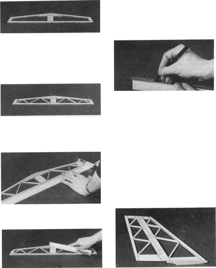
D 1. Tape waxed paper over the stabilizer drawing on the plan so you don't glue the parts to the plan. Using the plan as a guide, cut the 3/16" x 3/8" balsa pieces from SPRTS02. Punch out the die-cut Stab Tips, Stab Center and Stab Brace from SPRTS01 and sand the edges if necessary to remove any "fuzz''. Assemble the stab framework by pinning everything in place on the plan. Glue the parts together using thin CA glue.
D 2. Cut and sand the 1/8" x 3/16" "ribs" (from SPRTS03)tolength and glue them in place. NOTE: It is not necessary to get these ribs in the exact position shown on the plan.
D 3. Pin or tape the elevator (SPRTS04) in place behind the stab and use your razor saw to cut the ends offto match the stab. Sand the the two front comers of the stab to round them off.
D 4. Remove the stab from the plan and examine it for any open or bad joints. Fill any gaps with thick CA, then use your sanding block with medium grit sandpaper to sand both sides smooth. Carefully draw a centerline around the edges of the stab (this will help maintain symmetry when sanding).
D 5. Tape the elevator to the stab using masking tape and sand the leading edge ofthe stab, the stab tips and the elevator tips to a smooth rounded shape. The tips of the elevator should blend in nicely with the stab tips.
D 6. Remove the elevator and draw a center line down its leading edge. Use your sanding block to sand the same V- shape as you did on the rudder. The trailing edge should also be sanded to a smooth rounded shape. Apply thin CA the the tips of the elevator to harden the wood, and help protect it from damage.
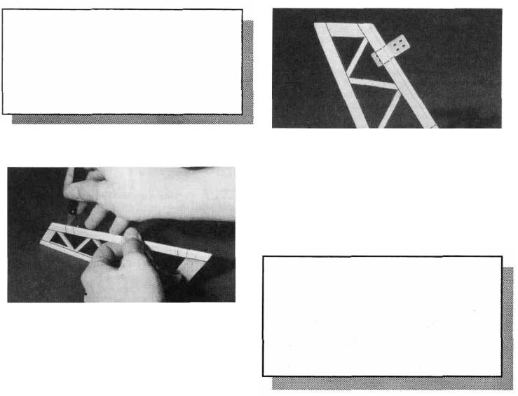
CUT THE HINGE SLOTS (Do not glue)
NOTE: One-piece molded polypropylene hinges are supplied in this kit. We have tested many different hinges and have found that these hinges are one of the best available. We recommend that you use these hinges and follow the instructions below to install them. If you choose to use these hinges or the "pinned"-type hinges, you should cut the hinge slots at this time. However, ifyou choose to use the one-piece hinges that are paper covered for CA glue installation, you may wait until after covering before cutting the hinge slots.
D 1. Lay the rudder and elevators on the plan and mark the hinge locations. Place the rudder against the fin TE and transfer the marks over to the fin. Place the elevator against the stab TE and transfer the marks over to the stab.
8
CAUTION!!!: You must use extreme care when cutting hinge slots with a hobby knife, to avoid cutting yourself! If the balsa part breaks while you are pushing on the knife, the blade could go into your hand before you know it! A good precaution is to wear leather gloves while performing the following steps.
D 2. Draw accurate centerlines down the trailing edge of the stab and the fin. Cut the hinge slots on these lines using a hobby knife or a slotting fork and slotting hook. (The recommended hinge slotting technique is listed below).
A.Begin by carefully cutting a very shallow slit at the hinge location. This first cut is to establish your cut in the right place, so concentrate on staying on the centerline and don't cut too deep!
B.Make three or four more cuts in the same line, going slightly deeper each time. As you make these additional cuts, work on going straight into the wood. Continue this process while "wiggling" the knife handle
forward and backward until the blade has reached the proper depth for the hinge.
C. Trial fit the hinge into the slot. If the hinge is difficult to push in, re-insert the knife and move it back and forth in the slot a few times to enlarge the slot.
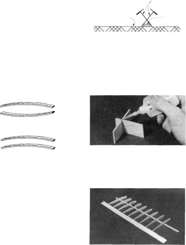
D 3. IMPORTANT! Condition or "break-in" the hinges by folding them back and forth several times.
D 4. Insert the hinges into the slots and trial fit the rudder and elevator in place on the fin and stab. Do not glue the hinges until after you have covered the model. The photo for this step is at the top of the next column.
WING ASSEMBLY
A DECISION YOU SHOULD MAKE NOW...
"WING CONFIGURATION"
The SPECTRA kit has two differentwing options: a twopiece wing or a one-piece wing. The two-piece wing is the standard way to build the wing and it is much easier to transport. The instructions alsoexplain how tobuild the wing in one piece which makes it a little stronger but makes it harder to transport in today's small cars
BUILD THE INNER WING PANELS
You'll need the following parts:
SPRTW01 |
1/8" Die-Cut Balsa Wing Ribs |
SPRTW02 |
1/16" Die-Cut Balsa Wing Ribs, W2. W2S |
SPRTW03 |
1/16" Die-Cut Balsa Wing Ribs, W2, W4- |
|
W10 |
SPRTW04 |
1/8" Die-Cut Plywood Dihedral Braces |
SPRTW07 |
1/16" Die-Cut Balsa Shear Webs |
SPRTW08 |
1/8" Die-Cut Plywood Clamps and Gauges |
SPRTW10 |
Shaped Balsa Leading Edge |
SPRTW 11 Shaped, Notched BalsaInnerTrailingEdge |
|
SPRTW13 |
1/8" x 5/16" x 23-1/2" Basswood Spars |
SPRTW17 |
1/16" x 3" x 24" Balsa Wing Sheeting |
NOTE: The wing is designed to be built as a two-piece wing; however, we also describe how to build a one-piece wing.
D 1. Tape the plan to your flat work surface, and cover the wing drawing with waxed paper. NOTE: If your work space is limited, you may cut the wing drawings apart from the rest of the plans.
D 2. The Shaped Wing Leading Edges (SPRTW10) are fastened together by thin strips of balsa. Separate them by
carefully cutting between the LE'S. Sand away the excess balsa that remains along the edges after cutting them apart, using a sanding block with 100-grit sandpaper. Be careful when cutting and sanding to follow the contour of the LE'S and don't sand any more than necessary, otherwise they may not match up with the ribs and sheeting.
D 3. Before using the 1/8" x 5/16" x 23-1/2" Basswood Spars (SPRTW13), examine them carefully for possible imperfections. Look for knots, soft spots, diagonal grain and any other imperfections. Ifpossible, position each spar so the imperfections are on the outer half of the wing panel (toward the tip), where they will be least affected by high stress. If the spars are warped slightly, "balance them out" by installing the warped spars in opposite directions (see sketch).
TWO WARPED SPARS INSTALLED
THIS W A Y WILL RESULT IN A
STRAIGHT WING
TWO WARPED SPARS INSTALLED
THIS W A Y WILL RESULT IN A
WARPED WING
NOTE: The spars may be cut slightly too long. The excess will be cut off later.
T-Pins
Work Surface |
Spar |
DD 7. Place the seven W-2 ribs (from SPRTW02 and SPRTW03) and the two W-2S ribs (from SPRTW02) on the spar in their approximate positions, work the ribs into the notches on the trailing edge but do not glue anything yet.
D 4. Carefully punch out all the die-cut 1/16" Balsa W2 and W2S Wing Ribs. Sand the edges slightly to remove any die-cutting irregularities. The W2S ribs have a die-cut notch to clear the spoilers in the SPIRIT kit and are not used in this kit so just treat them like a W2 rib and do not punch out the notch.
NOTE: Begin building the LEFT wing panel, starting at step 5 on page 10. Continue through step 8 on page 15. Next, repeat these steps to build the right wing panel.
DD 5. Pin one of the notched balsa Inner Trailing Edges (SPRTW 11) to the plan lining up the notches in the TE with the notches on the plan. Notice that the notches near W3 are only 1/16" wide since half of the 1/8" wide rib notch is in the inner T.E. and the other half is in the outer T.E..
DD 6. Place one of the 1/8" x 5/16" x 23-1/2" Basswood Inner Spars (SPRTW13) on the wing plan and pin the spar down with crossed T-pins as shown in the following sketch.
DD 8. Punch out the two Rib Gauge Pieces from the 1/8" die-cut plywood sheet (SPRTW08) and assemble them using CA. Notice that one end of the gauge is slanted at a 5 degree angle for positioning the end ribs. The other 3 ends are perpendicular and can be used to keep parts 90 degrees to the work surface.
DD 9. Make sure the ribs are properly positioned according to the plans and glue them in place using thick CA at the spar joint and a drop of thin CA at the trailing edge joint. Use
10
the square end of the rib gauge to keep the ribs perpendicular to the work surface.
DD 10. Trial fit the top 1/8" x 5/16" x 23-1/2" Basswood Inner Spar (SPRTW13) into the notches in the ribs by carefully pushing the spar completely down into the notches. Make sure the top spar is lined up lengthwise with the bottom spar. Remove the spar and glue it in place by applying thick CA to the notches before the spar is put back in place.
DD 11. Position a Pre-shaped Leading Edge (SPRTW 10) in place over the plans. NOTE: These leading edges are NOT symmetrical. Refer to the wing end view on the plan to determine which way they should be installed. Carefully hold the leading edge against one ofthe end W-2 ribs and note that it is wider than the front of the rib. This is because the 1/ 16" balsa leading edge top sheeting will be added later. Align the lower surface of the leading edge with the bottom of the rib and glue it in place with a drop of thin CA (there must be a 1/16" gap between the top of the rib and the top of the LE so the sheeting will fit). Lift up the other end of the leading edge, align it with the bottom of the opposite end W-2 and glue it with a drop of thin CA. Go down the line and glue the remaining ribs to the leading edge one at a time so you can make sure they are aligned. CA Accelerator may come in handy for speeding up this process if you don't want to hold the LE in place long enough for the glue to cure naturally.
DD 12. Locate the 1/16" Balsa Die-Cut Shear Web Sheet (SPRTW07) and notice that all of the shear webs are not the same. The webs between the stamped number 2's are for use on the inner panel. The webs between the 2 and the 10 are for the outer panel and each one of these is a different size so keep them in the sheet until they are ready to be used.
Punch out all of the "2" shear webs.
DD 13. Trial fit one of the webs in place between the first two W-2 ribs. You may have to sand it slightly to get it to fit. Glue the shear web in place on the back of the spars using thick CA. The webs should be centered between the spars. It is important to do a good job of gluing these in place as they are responsible for most of the wing's strength. C-2 Clamps from the 1/8" Die-Cut Plywood Sheet (SPRTW08) can be used to help hold the webs in place while the glue cures.
DD 14. Install the remaining balsa shear webs. Note that the webs are only installed between the ribs already glued in place. Three webs are also installed on the front of the spars in the first three rib "bays". Remove the T-Pins as the webs are installed but make sure the panel is kept flat throughout this process.
IF YOU ARE BUILDING A ONE-PIECE WING, SKIP AHEAD TO "BUILD THE OUTER WING PANELS" ON PAGE 13. STEPS 15 THROUGH 23 ARE FOR A 2- PIECE WING ONLY.
DD 15. Locate the 1/8" die-cut sheet (SPRTW04) that contains the Dihedral Braces, the Leading Edge Brace and the Wing Joiner Lamination. Line a ruler up with the two embossed cut marks and draw a line across both of the dihedral braces.
DD 16. Punch out the two dihedral braces and cut them in half with a razor saw along the lines you just drew. Note: these braces are supplied in one-piece for the one piece option. Also punch out the wing joiner lamination from that
11
 Loading...