


INSTRUCTION MANUAL
WARRANTY
Great Planes® Model Manufacturing Co. guarantees this kit to be free from defects in both material and workmanship at the date of purchase. This warranty does not cover any component parts damaged by use or modification. In no case shall Great Planes’ liability exceed the original cost of the purchased kit. Further, Great Planes reserves the right to change or modify this warranty without notice.
In that Great Planes has no control over the final assembly or material used for final assembly, no liability shall be assumed nor accepted for any damage resulting from the use by the user of the final user-assembled product. By the act of using the user-assembled product, the user accepts all resulting liability.
If the buyers are not prepared to accept the liability associated with the use of this product, they are advised to return this kit immediately in new and unused condition to the place of purchase.
READ THROUGH THIS INSTRUCTION MANUAL FIRST. IT CONTAINS IMPORTANT INSTRUCTIONS AND WARNINGS CONCERNING THE ASSEMBLY AND USE OF THIS MODEL.
P.O. Box 788 Urbana, IL 61801 (217) 398-8970
productsupport@greatplanes.com
Entire Contents © Copyright 2002 |
GPMZ0235 for GPMA1218 V1.1 |

TABLE OF CONTENTS |
|
INTRODUCTION ............................................................... |
2 |
PRECAUTIONS................................................................. |
3 |
DECISIONS YOU MUST MAKE........................................ |
4 |
Radio equipment............................................................ |
4 |
Engine recommendations .............................................. |
4 |
ADDITIONAL ITEMS REQUIRED ................................... |
4 |
Hardware and accessories ............................................ |
4 |
Covering accessories..................................................... |
4 |
Adhesives and building supplies.................................... |
4 |
OPTIONAL ITEMS............................................................ |
5 |
IMPORTANT BUILDING NOTES...................................... |
5 |
MonoKote® information................................................... |
5 |
Metric conversions ......................................................... |
5 |
Kit parts.......................................................................... |
6 |
Ordering replacement parts ........................................... |
7 |
PREPARATIONS............................................................... |
8 |
ASSEMBLE THE WINGS.................................................. |
8 |
Install the ailerons .......................................................... |
8 |
Join the bottom wing.................................................... |
11 |
Join the top wing.......................................................... |
12 |
ASSEMBLE THE FUSELAGE ........................................ |
13 |
Mount the bottom wing ................................................ |
13 |
Mount the top wing ...................................................... |
14 |
Mount the stab and fin ................................................. |
16 |
Install the servos.......................................................... |
18 |
Mount the landing gear ................................................ |
20 |
Mount the engine ......................................................... |
22 |
Assemble and install the fuel tank ............................... |
26 |
Mount the cowling ........................................................ |
26 |
Assemble and install the spinner ................................. |
27 |
Install the radio gear .................................................... |
28 |
Install the flying wires................................................... |
30 |
Finishing touches ......................................................... |
32 |
GET THE MODEL READY TO FLY................................. |
33 |
Check the control directions ........................................ |
33 |
Set the control throws .................................................. |
34 |
Balance the model (C.G.) ............................................ |
34 |
Balance the model laterally.......................................... |
35 |
PREFLIGHT .................................................................... |
35 |
Identify your model....................................................... |
35 |
Charge the batteries .................................................... |
35 |
Balance the propeller................................................... |
35 |
Ground check............................................................... |
36 |
Range check ................................................................ |
36 |
Engine safety precautions............................................ |
36 |
AMA Safety Code ........................................................ |
36 |
IMAA Safety Code ....................................................... |
37 |
FLYING............................................................................ |
39 |
Fuel mixture adjustments............................................. |
39 |
Takeoff.......................................................................... |
39 |
Flight ............................................................................ |
39 |
Landing ........................................................... |
back cover |
Identification tag.............................................. |
back cover |
INTRODUCTION
Congratulations and thank you for purchasing the Great Planes Pitts Special S-2S ARF. We at Great Planes R&D were very pleased with the appearance and performance of this amazing model aircraft. Please look it over carefully and notice the quality with which this ARF has been built. It's expertly engineered, to provide excellent aerobatic potential AND a very stable and gentle flying R/C model at low speeds.
The full sized Pitts Special has won more unlimited class championships than any other airplane. Curtis H. Pitts started to design the Pitts Special in 1942 in Jacksonville, Florida. The initial Pitts Special, powered by a Franklin 90 hp engine, flew for the first time during 1944. Over the next 25 years, the Pitts Special was available only as a homebuilt aircraft. Over this period it was continuously refined to improve its aerobatic performance. By 1962, the standard engine had grown to 180 hp, and in 1966 its wings adopted a symmetric profile to make the inverted flight characteristics equal to those of normal flying.
The Pitts Special S-2S has a single seat in a fuselage that is 12 inches longer than previous models. The aircraft is light and strong. Built with steel tubes, wood, and canvas, the aircraft's only fully metallic part is a Lycoming AE10-540- D4A5 4 cylinder engine producing 260 hp. This allows the Pitts to reach extremely high levels of performance for the execution of the most demanding aerobatic maneuvers.
Aviat Aircraft Inc. purchased the manufacturing rights of the Pitts Special in March 1991. The Pitts Special remains in production in the original factory located in Afton, Wyoming.
For the latest technical updates or manual corrections to the Great Planes Pitts Special S-2S ARF, visit the web site listed below and select the Great Planes Pitts Special S-2S ARF. If there is new technical information or changes to this model a "tech notice" box will appear in the upper left corner of the page.
http://www.greatplanes.com/airplanes/index.html
IMAA INFORMATION
The Great Planes Pitts Special S-2S ARF is an excellent sport-scale model and is eligible to fly in IMAA events. The IMAA (International Miniature Aircraft Association) is an organization that promotes non-competitive flying of giantscale models. If you plan to attend an IMAA event, contact the IMAA for a copy of the IMAA Safety Code at the address or telephone number below.
IMAA
205 S. Hilldale Road
Salina, KS 67401 (866) 366-4622
Or via the Internet at: http://www.fly-imaa.org
2

|
|
|
|
6. You must check the operation of the model before every |
||
|
|
|
|
|||
|
SCALE COMPETITION |
|
|
flight to insure that all equipment is operating and that the |
||
|
|
|
model has remained structurally sound. Be sure to check |
|||
|
|
|
|
|||
|
|
|
|
clevises or other connectors often and replace them if they |
||
|
|
|
|
|||
Though the Great Planes Pitts Special is an ARF and may not |
show any signs of wear or fatigue. |
|||||
have the same level of detail as an "all-out" scratch-built |
|
|
|
|||
competition model, it is a scale model nonetheless and is |
7. If you are not already an experienced R/C pilot, you should |
|||||
therefore eligible to compete in the Fun Scale class in AMA |
fly the model only with the help of a competent, experienced |
|||||
competition (we receive many favorable reports of Great |
R/C pilot. |
|||||
Planes ARFs in scale competition!). In Fun Scale, the "builder |
|
|
|
|||
of the model" rule does not apply. To receive the five points for |
8. While this kit has been flight tested to exceed normal use, |
|||||
scale documentation, the only proof required that a full size |
if the plane will be used for extremely high stress flying, |
|||||
aircraft of this type in this paint/markings scheme did exist is a |
such as extreme aerobatics, the modeler is responsible for |
|||||
single sheet such as a kit box cover from a plastic model, a |
taking steps to reinforce the high stress points. |
|||||
photo, or a profile painting, etc. If the photo is in black and white |
|
|
|
|||
other written documentation of color must be provided. Contact |
9. WARNING: The cowl, wheel pants and wing struts included |
|||||
the AMA for a rule book with full details. |
in this kit are made of fiberglass, the fibers of which may cause |
|||||
|
|
|
|
eye, skin and respiratory tract irritation. Never blow into a part |
||
If you would like photos of the full-size Great Planes Pitts |
(wheel pant, cowl) to remove fiberglass dust, as the dust will |
|||||
Special for scale documentation, or if you would like to study |
blow back into your eyes. Always wear safety goggles, a |
|||||
the photos to add more scale details, photo packs are |
particle mask and rubber gloves when grinding, drilling and |
|||||
available from: |
sanding fiberglass parts. Vacuum the parts and the work area |
|||||
|
|
|
|
thoroughly after working with fiberglass parts. |
||
|
Bob's Aircraft Documentation |
|
|
|
||
|
3114 Yukon Ave |
|
|
|
||
|
We, as the kit manufacturer, provide you with a top |
|
||||
|
Costa Mesa, CA 92626 |
|
|
|||
|
|
quality kit and instructions, but ultimately the quality and |
|
|||
|
|
|
|
|
|
|
|
Telephone: (714) 979-8058 |
|
flyability of your finished model depends on how you |
|
||
|
|
assemble it; therefore, we cannot in any way guarantee |
|
|||
|
Fax: (714) 979-7279 |
|
|
|||
|
|
the performance of your completed model, and no |
|
|||
|
e-mail: www.bobsairdoc.com |
|
|
|||
|
|
representations are expressed or implied as to the |
|
|||
|
|
|
|
|
|
|
|
|
|
|
|
performance or safety of your completed model. |
|
|
|
|
|
|
|
|
|
|
|
|
|
||
|
PROTECT YOUR MODEL,YOURSELF |
|
|
Remember: Take your time and follow the instructions to |
||
|
& OTHERS...FOLLOW THESE |
|
|
end up with a quality model that is straight and true. |
||
|
IMPORTANT SAFETY PRECAUTIONS |
|
|
If you have not flown this type of model before, we |
||
|
|
|
|
|||
|
|
|
|
|||
1. Your Great Planes Pitts Special should not be considered |
recommend that you get the assistance of an experienced |
|||||
a toy, but rather a sophisticated, working model that |
pilot in your R/C club for your first flights. If you're not a |
|||||
functions very much like a full-size airplane. Because of its |
member of a club, your local hobby shop has information |
|||||
performance capabilities, the Great Planes Pitts Special, if |
about clubs in your area whose membership includes |
|||||
not assembled and operated correctly, could possibly cause |
experienced pilots. |
|||||
injury to yourself or spectators and damage to property. |
|
|
|
|||
|
|
|
|
In addition to joining an R/C club, we strongly recommend you |
||
2.You must assemble the model according to the join the AMA (Academy of Model Aeronautics). AMA
instructions. Do not alter or modify the model, as doing so |
membership is required to fly at AMA sanctioned clubs. There |
|
may result in an unsafe or unflyable model. In a few cases |
are over 2,500 AMA chartered clubs across the country. |
|
the instructions may differ slightly from the photos. In those |
Among other benefits, the AMA provides insurance to its |
|
instances the written instructions should be considered as |
members who fly at sanctioned sites and events. Additionally, |
|
correct. |
training programs and instructors are available at AMA club |
|
|
|
sites to help you get started the right way. Contact the AMA at |
3. |
You must take time to build straight, true and strong. |
the address or toll-free phone number below: |
4. |
You must use an R/C radio system that is in first-class |
Academy of Model Aeronautics |
condition, and a correctly sized engine and components |
5151 East Memorial Drive |
|
(fuel tank, wheels, etc.) throughout the building process. |
Muncie, IN 47302-9252 |
|
|
|
Tele. (800) 435-9262 |
5. |
You must correctly install all R/C and other components |
Fax (765) 741-0057 |
so that the model operates correctly on the ground and in |
Or via the Internet at: http://www.modelaircraft.org |
|
the air. |
|
|
3
DECISIONS YOU MUST MAKE
This is a partial list of items required to finish the Pitts Special that may require planning or decision-making before starting assemble. Order numbers are provided in parentheses.
Radio Equipment
The Pitts Special requires a minimum 4 channel radio system such as the Futaba® 4VF (FUTJ62**). Due to the aerobatic capabilities of this model aircraft we strongly recommend that servos with a minimum of 50 oz.-in. of torque be used.
You will also need other extensions and Y-harnesses. These requirements will differ based on the manner in which you configure your set-up of this model aircraft. For example, you can set this model aircraft up with two aileron servos only on the bottom wing and mechanically connect those ailerons to the ailerons in the top wing with connecting rods. Using the four aileron servo set-up will take more extensions and Y- harnesses.
Also you may opt to not use a Y-harness set-up on your elevators by using a mixing function on your transmitter if it has those capabilities. The extensions needed will also vary based on the location of your battery pack and your receiver. So be sure to plan your set-up carefully.Then, based on your decisions, you can determine what items you will need.
Engine Recommendations
The following engines are recommended and have been tested for use in the Pitts Special:
O.S.® 1.60 FX two-stroke (OSMG0661)
O.S. 1.60 FX-FI two-stroke, fuel injected (OSMG0662) SuperTigre® G-4500 two-stroke (SUPG0270)
O.S. FT-300 Gemini Twin four-stroke (OSMG1250) US Engines™ 41cc 2.5 Gas Engine (USEG0041)
Remember that this is a scale model that is intended to fly at scale-like speeds, so throttle management should be practiced.
If you choose a lighter weight engine you will need to add nose weight to achieve the proper balance. This model has been tested with the lighter weight OS 1.60 FX plus added weight to balance. This combination flew very scale-like and aerobatic. Should you wish to minimize the total weight of your model, you may want to consider moving the servos from the tail location forward into the area behind the fuel tank and just inside the bottom wing. Of course, you will need to connect the servos to the control surfaces with pushrods that are not installed or supplied.This option would allow you to balance the model properly with less weight added to the nose of the model.
ADDITIONAL ITEMS REQUIRED
Hardware and Accessories
This is the list of hardware and accessories required to finish the Great Planes Pitts Special. Order numbers are provided in parentheses.
Propellers-Follow engine manufacturer's recommendations
R/C foam rubber 1/4" (HCAQ1000) or 1/2” (HCAQ1050)
Servo extensions
Y-Harnesses
Covering Accessories
21st Century® sealing iron (COVR2700)
21st Century trim seal iron (COVR2750)
21st Century cover sock (COVR2702)
Adhesives and Building Supplies
In addition to common household tools and hobby tools, this is the “short list” of the most important items required to assemble the Pitts Special. Great Planes Pro™ CA and Epoxy glue are recommended.
30-Minute Epoxy (GPMR6047)
6-Minute Epoxy (GPMR6045)
Threadlocker (GPMR6060)
1/2 oz. Thin Pro CA (GPMR6001)
1/2 oz. Medium Pro CA+ (GPMR6007)
3’ Medium fuel tubing (GPMQ4131)
Hobby knife (HCAR0105)
#11 blades (HCAR0211)
Mixing Sticks (GPMR8055)
Small T-pins (HCAR5100)
Builder’s triangle (HCAR0480)
Electric drill and 1/16" [1.6mm], 5/64" [2mm], 3/32" [2.4mm], 1/8" [3.2mm], 9/64" [3.5mm],
3/16" [4.8mm], 7/32" [5.6mm], and 17/64" [6.7mm], drill bits
Small Phillips (HCAR1024) and flat blade (HCAR1002) screwdrivers
Pliers with wire cutter (HCAR0630)
4
OPTIONAL ITEMS
Here is a list of optional tools mentioned in the manual that will help you assemble the Pitts Special ARF.
Switch and Charge Jack Mounting Set (GPMM1000)
Easy-Touch™ Bar Sander (GPMR6170)
Easy Fueler™ fuel filling valve for glow fuel (GPMQ4160)
Hobbico® Servo Horn Drill (HCAR0698)
1/3-scale pilot (DGAQ2000)
Top Flite Precision Magnetic Prop Balancer™ (TOPQ5700)
Great Planes Fingertip Prop Balancer (GPMQ5000)
Straightedge with scale (HCAR0475)
Cutting mat (HCAR0456)
Masking Tape (TOPR8018)
CA Debonder (GPMR6039)
CA Applicator tips (GPMR6033)
CA accelerator (GPMR6034)
R/C-56 Canopy Glue (JOZR5007)
Epoxy Brushes (GPMR8060)
Denatured Alcohol (for epoxy clean up)
Curved Tip Canopy Scissors for Trimming Plastic Parts (HCAR0667)
Dead Center™ Engine Mount Hole Locator (GPMR8130)
Great Planes Receiver Guard (GPMM1010)
Great Planes AccuThrow™ Deflection Gauge (for measuring control throws, GPMR2405)
Hobbico Hot Knife (HCAR0770)
Hobby Retractable Tape Measure (HCAR0478)
IMPORTANT BUILDING NOTES
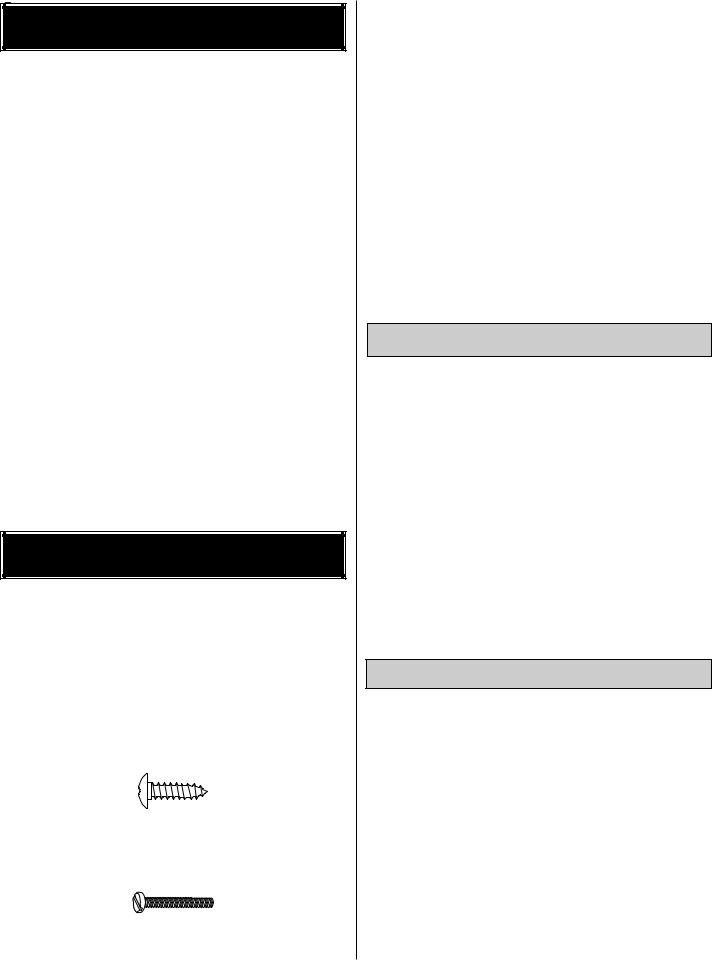
There are two types of screws used in this kit:
Sheet metal screws are designated by a number and a length. For example #6 x 3/4" long [19.1mm]
This is a number six screw that is 3/4" [19.1mm] long.
Truss head screws are designated by a number and a length. For example #8 x 5/8" [15.9mm]
This is a number eight screw that is 5/8" [15.9mm] long.
Machine screws are designated by a number, threads per inch, and a length. For example 4-40 x 3/4" long [19.1mm]
This is a number four screw that is 3/4" [19.1mm] long with forty threads per inch.
5
•When you see the term test fit in the instructions, it means that you should first position the part on the assembly without using any glue, then slightly modify or custom fit the part as necessary for the best fit.
•Whenever the term glue is written you should rely upon your experience to decide what type of glue to use. When a specific type of adhesive works best for that step, the instructions will tell you what glue is recommended.
•Whenever just epoxy is specified you may use either 30-minute epoxy or 6-minute epoxy. When 30-minute epoxy is specified, it is highly recommended that you use only 30-minute (or 45-minute) epoxy because you will need the working time and/or the additional strength.
• Photos and sketches are placed before the step they refer to. Frequently you can study photos in following steps to get another view of the same parts.
MonoKote Information
The Pitts Special ARF is factory-covered with Top Flite MonoKote film. Should repairs ever be required, MonoKote can be patched with additional MonoKote purchased separately. MonoKote is packaged in six-foot rolls, but some hobby shops also sell it by the foot. If only a small piece of MonoKote is needed for a minor patch, perhaps a fellow modeler would give you some. MonoKote is applied with a model airplane covering iron, but in an emergency a regular iron could be used. A roll of MonoKote includes full instructions for application. Following are the colors used on this model and order numbers for six-foot rolls.
True Red TOPQ0227
Black TOPQ0208
White TOPQ0204
Metric Conversions
1" = 25.4mm (conversion factor)
1/64" |
= .4mm |
1" |
= 25.4mm |
1/32" |
= .8mm |
2" |
= 50.8mm |
1/16" |
= 1.6mm |
3" |
= 76.2mm |
3/32" |
= 2.4mm |
6" |
= 152.4mm |
1/8" |
= 3.2mm |
12" |
= 304.8mm |
5/32" |
= 4mm |
15" |
= 381mm |
3/16" |
= 4.8mm |
18" |
= 457.2mm |
1/4" |
= 6.4mm |
21" |
= 533.4mm |
3/8" |
= 9.5mm |
24" |
= 609.6mm |
1/2" |
= 12.7mm |
30" |
= 762mm |
5/8" |
= 15.9mm |
36" = 914.4mm |
|
3/4" |
= 19mm |
|
|
|
|
|
|
|
|
Kit Contents |
|
|
|
||
|
|
|
|
|
|
|
|
|
|
|
|
|
|
|
|
|
|
|
|
|
|
|
|
|
1 |
|
|
|
|
|
|
|
|
||
|
|
|
|
|
|
|
|
|
|
|
|
|
2 |
|
|
|
|
|
|
|
9 |
||
|
|
|
|
|
|
|
|
|
|
|
|
|
3 |
|
|
|
|
|
|
|
10 |
||
|
|
|
|
|
|
|
|
|
|
|
|
|
4 |
|
|
|
|
|
|
|
11 |
||
|
|
|
|
|
|
|
|
|
|
|
|
|
5 |
|
|
|
|
|
|
|
12 |
||
|
|
|
|
|
|
|
|
|
|||
|
6 |
|
|
|
|
|
|
|
|
||
|
|
|
|
|
|
|
13 |
||||
|
|
|
|
|
|
|
|
|
|||
|
7 |
|
|
|
|
|
|
|
|
||
|
|
|
|
|
|
|
|
|
|||
|
8 |
|
|
|
|
|
|
|
|
||
|
|
|
|
|
|
|
14 |
||||
|
|
|
|
|
|
|
|
|
|
|
|
|
|
|
|
|
|
|
|
|
|
|
|
|
|
|
|
|
|
|
|
|
|
|
15 |
|
|
|
|
|
|
|
|
|
|
|
|
|
|
|
|
|
|
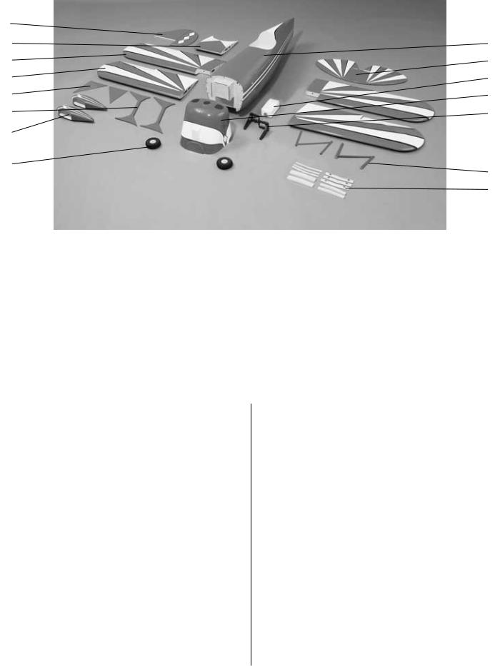
Parts photographed |
|
|
|||
Key # Description |
Qty |
|
Key # |
Description |
Qty |
||||||
|
|||||||||||
1. |
FIN with/ RUDDER .......................................... |
(1) |
|
9. |
FUSELAGE ..................................................... |
(1) |
|||||
2. |
TOP WING CENTER SECTION...................... |
(1) |
|
10. |
STAB with/ELEVATORS .................................. |
(1) |
|||||
3. |
BOTTOM WING with/AILERONS ............. |
(2 Pcs) |
|
11. |
FUEL TANK W/HARDWARE ........................... |
(1) |
|||||
4. |
TOP WING with/AILERONS..................... |
(2 Pcs) |
|
12. |
PAINTED FIBERGLASS COWL ...................... |
(1) |
|||||
5. |
LANDING GEAR SPATS ................................ |
(2) |
|
13. |
ENGINE MOUNT L&R ............................. |
(2 Pcs) |
|||||
6. |
PAINTED FIBERGLASS STRUTS ................. |
(2) |
|
14. |
PAINTED CABANE STRUTS ......................... |
(2) |
|||||
7. |
PAINTED FIBERGLASS WHEEL PANTS |
......(2) |
|
15. |
WING JOINERS .................................... |
(10 Pcs) |
|||||
8. |
4” WHEELS .................................................... |
(2) |
|
|
|
|
|
||||
|
|
|
|
|
|
|
|
|
|
|
|
Parts not photographed
(1)PAINTED CANOPY
(1)DECAL SHEET
(1)PAINTED ALUMINUM LANDING GEAR
(1)ALUMINUM SPINNER
(1)PLYWOOD TRAY
(for optional mounting receiver and battery pack)
(4)8/32" x 1" SHCS
(socket-head cap screws for attaching engine mount)
(4)8/32" BLIND NUTS (for attaching engine mount)
(4)6/32" x 1/8" SET SCREWS (for wheel collars)
(4)5/32" WHEEL COLLARS (for attaching main wheels)
(2)2" x 5/32" AXLES
(2) 5/16" LOCK NUTS (for attaching axles)
(2)¼"-20 NYLON BOLTS (attach wing to fuse)
(1)NYLON CLEVIS (throttle)
(7)4-40 SOLDER CLEVISES (ailerons, elevators, rudder servos)
(1)2-56 NYLON FASLINKS (throttle)
(7)HEAVY DUTY CONTROL HORNS (ailerons, elevators, rudder)
(3)HEAVY DUTY CONTROL HORN BACK-PLATES
(elevators and rudder)
(40) SILICONE CLEVIS RETAINERS (all clevis applications)
(1) 2" x 9" CA HINGE STRIP (all control surfaces)
(2)2-56 x 12" THREADED ONE END ROD (throttle and tail wheel control rod)
(7)4-40 x 12" THREADED ONE END ROD (control surfaces push rods)
(8)#8 WASHERS
(engine mount to firewall and engine to mount)
(13) 4-40 NYLON STOP NUTS (for attaching struts, cabanes, and brackets for tail surface flying wires)
(10) #4 WASHERS (for attaching struts and cabanes)
(6)#2 x 1/2" PHILLIPS HEAD SCREWS (for attaching cowl)
(4)8-32 x ¾" SOCKET HEAD SCREWS (for mounting engine to mount)
(12) #2 FLAT WASHER
(for attaching landing gear spats and attaching cowl)
(7)4-40 x 5/8" PHILLIPS HEAD MACHINE SCREWS (for attaching wheel pants and brackets for tail surface flying wires)
(25) 2-56 THREADED METAL CLEVISES (for flying wires, (1) tail gear linkage)
(25) 2-56 NUTS
(for flying wires and tail wheel steering pushrod)
6
Parts not photographed (continued)
(34) #4 x 1/2" WOOD SCREWS (for attaching cabanes to fuselage, brackets for struts and wires, aileron control horns, tail gear to fuselage)
(4) 4-40 BLIND NUTS (for attaching wheel pants)
(7) 4-40 THREADED METAL CLEVISES (control surfaces)
(7) 4-40 HEX NUTS (control surface push rods)
(6)2-56 x 1/2" PHILLIPS MACHINE SCREWS (for attaching spats to landing gear)
(6)#8 x 5/8" PHILLIPS TRUSS HEAD SCREWS (for attaching landing gear)
(2) 3-32 WHEEL COLLARS (for attaching tail gear linkage)
(2)WHEEL COLLAR SET SCREW (for attaching tail gear linkage)
(1) NYLON TORQUE ROD HORN (tail gear linkage)
(1)2-56 SOLDER METAL CLEVIS (for attaching tail gear linkage)
(24) ALUMINUM CRIMP TUBES (for attaching flying wires) (20) 2-56 THREADED BRASS ENDS (drilled for flying wires)
(4)3/32 [2.4 mm] x 1" [25 mm] x 2" [51 mm] PLYWOOD PLATES (for mounting wheel pants)
(4)3/32 [2.4 mm] x 1" [25 mm] x 1" [25 mm] PLYWOOD PLATES (for wheel pant bearing blocks)
(1)FLYING WIRE
(2)90-DEGREE COMPOUND BEND BRACKETS
(4)90-DEGREE BRACKETS
(8)45-DEGREE BRACKETS
(4)110-DEGREE COMPOUND BEND BRACKETS
(4)70-DEGREE COMPOUND BEND BRACKETS
(8)70-DEGREE BRACKETS
(6)COWL MOUNTING BLOCKS (for attaching cowl to fuselage)
(2)3/8" x 1" DOWEL (for bottom wing hold-down)
(10)4-40 x 1/2" SOCKET HEAD CAP SCREWS
(for attaching top wing to cabanes and interplane struts)
(12)4-40 x 3/4" SOCKET HEAD CAP SCREWS
(for attaching control horns to elevators and rudder)
(6)2-56 STOP NUTS
(for attaching spats onto landing gear)
(1)TAIL WHEEL ASSEMBLY
Ordering Replacement Parts
To order replacement parts for the Great Planes Pitts Special ARF, use the order numbers in the Replacement Parts List that follows. Replacement parts are available only as listed. Not all parts are available separately (an aileron cannot be purchased separately, but is only available with the wing kit). Replacement parts are not available from Product Support, but can be purchased from hobby shops or mail order/Internet order firms. Hardware items (screws, nuts, bolts) are also available from these outlets. If you need assistance locating a dealer to purchase parts, visit www.greatplanes.com and click on “Where to Buy.” If this kit is missing parts, contact Great Planes Product Support.
Replacement Parts List
Order Number . |
.Description . . |
. . . .How to purchase |
GPMA2248 . . . . . |
COWL |
Contact hobby |
GPMA2249 . . . . . |
WHEEL PANTS |
supplier |
GPMA2250 . . . . . |
TOP WING SET |
|
GPMA2251 . . . . . |
BOTTOM WING SET |
|
GPMA2252 . . . . . |
FUSE KIT |
|
GPMA2253 . . . . . |
TAIL KIT |
|
GPMA2254 . . . . . |
CANOPY |
|
GPMA2255 . . . . . |
LANDING GEAR |
|
GPMZ0235 . . . . . |
INSTRUCTION MANUAL |
|
|
Missing pieces |
. . . . .Contact Product |
|
|
Support |
|
Full-size plans . |
. . . . . .Not available |
Before starting to assemble, use the Kit Contents list to take an inventory of this kit to make sure it is complete. Inspect the parts to make sure they are of acceptable quality. If any parts are missing or are not of acceptable quality, or if you need assistance with assembly, contact
Great Planes Product Support. When reporting defective or missing parts, use the part names exactly as they are written in the Kit Contents list on the previous page.
Great Planes Product Support:
Phone: (217) 398-8970
Fax: (217) 398-7721
E-mail: productsupport@greatplanes.com
You can also check our web site at for the latest Pitts Special updates.
7
PREPARATIONS
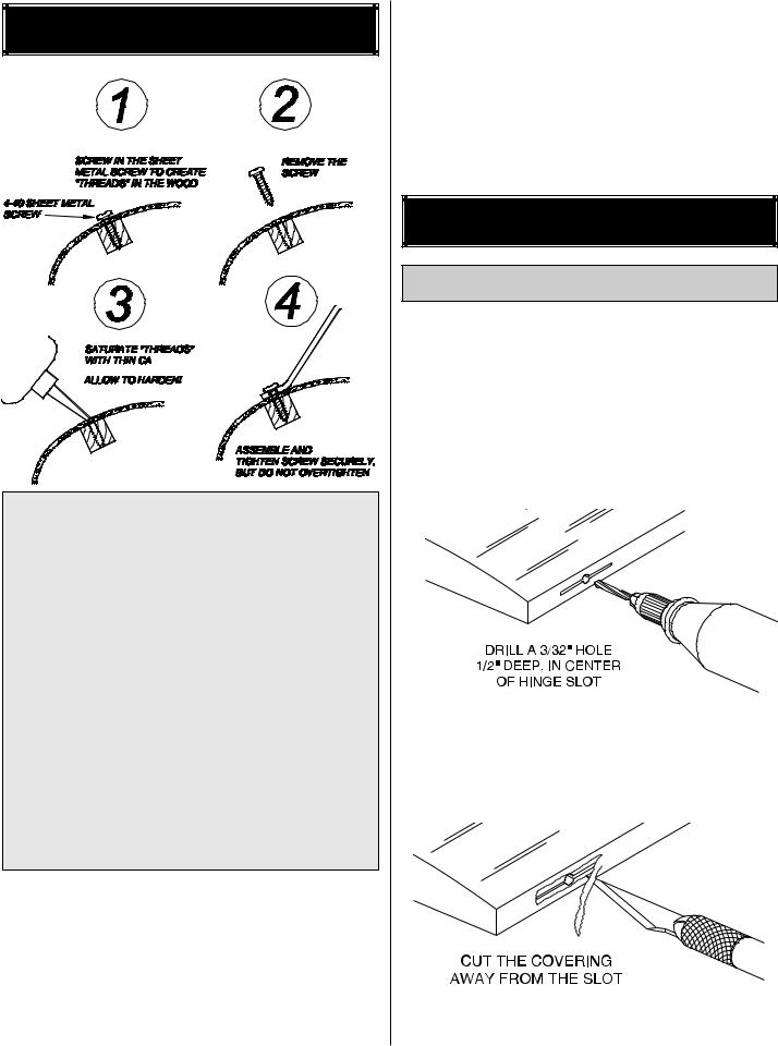
IMPORTANT NOTE: While assembling the Great Planes Pitts Special ARF, you will encounter a number of areas that require the installation of various brackets and other items. Most of the locations for these attachments have predrilled holes for these applications. The attachment screws do fit correctly but tightly. We highly recommend that you first drive the attachment screws into the predrilled holes with a regular screwdriver, then remove each screw, and thoroughly saturate the threads you have created in the hardwood with thin CA. After letting the CA set completely, continue with the assembly by driving the screws back into the threads you have created, being careful not to overtighten. Since these areas are subject to high stress, we strongly recommend that you DO NOT use an electric or battery powered drill or screwdriver for this as you can very easily overtighten the attachment screws and weaken the threads you have created in the hardwood blocks. Use this technique on all areas of the model when you attach anything to the model using screws. Extensive testing of this technique has shown that this method greatly increases the strength of the model.
1. If you have not done so already, remove the major parts of the kit from the box (wings, fuse, cowl, tail parts, etc.) and inspect them for damage. If any parts are damaged or missing, contact Product Support at the address or telephone number listed on page 3.
2. Remove the masking tape and separate the ailerons from the wing, the rudder from the fin and the elevators from the stab. If necessary, tighten the covering with a
covering iron on high heat. Use a covering sock on the iron to prevent scratches on the covering. Apply pressure over sheeted areas to thoroughly bond the covering to the wood.
3. In this manual you will notice boxes placed in front of each assembly step. These boxes are provided so that you may place check marks in them as you progress through the assembly process. If multiple boxes are present, this step needs to be repeated.
ASSEMBLE THE WINGS
Install the Ailerons
Important note: The Pitts Special ARF is capable of being assembled with the option of using four aileron servos. Or two aileron servos could be used in the bottom wing only, along with connecting rods between the top and bottom ailerons. In this manual we will show only the use of four aileron servos, but extensive testing was performed with the two aileron servo equipped version. This testing resulted in very positive response. Even during our very demanding stress testing, no problems were found.
1. Drill a 3/32" (2.4mm) hole, 1/2" (13mm) deep in the center of each hinge slot to allow the CA to “wick” in. Followup with a #11 blade to clean out the slots. Hint: If you have one, use a high-speed rotary tool to drill the holes.
2. Use a sharp #11 blade to cut a strip of covering from the aileron hinge slots in all four wing halves and ailerons.
8
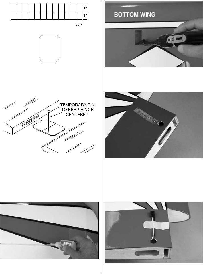
3. Cut twenty-one 3/4" (19mm) x 1" (25mm) hinges from the CA hinge strip. Snip off the corners as shown so they go in easier. Insert three of the hinges into the aileron hinge slots of each wing half. The rest of the hinges are for the elevators and rudder.
4. Test fit the aileron to the wing with the hinges. If the hinges don’t remain centered, stick a pin through the middle of the hinge to hold it in position.
5. Remove any pins you may have inserted into the hinges. Adjust the aileron so there is a small gap between the LE of the aileron and the wing. The gap should be just small enough to see light through or to slip a piece of paper through.
6. Apply six drops of thin CA to the top and bottom of each hinge. Do not use CA accelerator. After the CA has fully hardened, test the hinges by pulling on the aileron.
7. Cut the covering 1/8" (3mm) inside the opening in this wing half for the aileron servo. Use a trim iron to seal the covering to the edges of the opening.
8. Cut the covering away from the hole in the top of the bottom wing halves and feed the string, which is taped to the root rib, through the hole in top of the wing. Re-tape it securely near the hole. This step is different for the two top wing halves. There is one hole in the center of the top wing center section. Remove the covering from this hole also.
9. Connect a 12" (305mm) servo extension wire (HCAM2711) to an aileron servo lead and secure it with
9
tape or heat shrink material. Tie the string to the aileron servo extension and pull the wire out of the hole on top of the bottom wing halves with the string. Tape the connector to the wing to prevent it from falling back inside the wing. Then discard the string. The end of the aileron extension in the top wing halves should be taped to the wing halves until it is time to join them with the center section of the wing. This is covered in detail later in this manual.
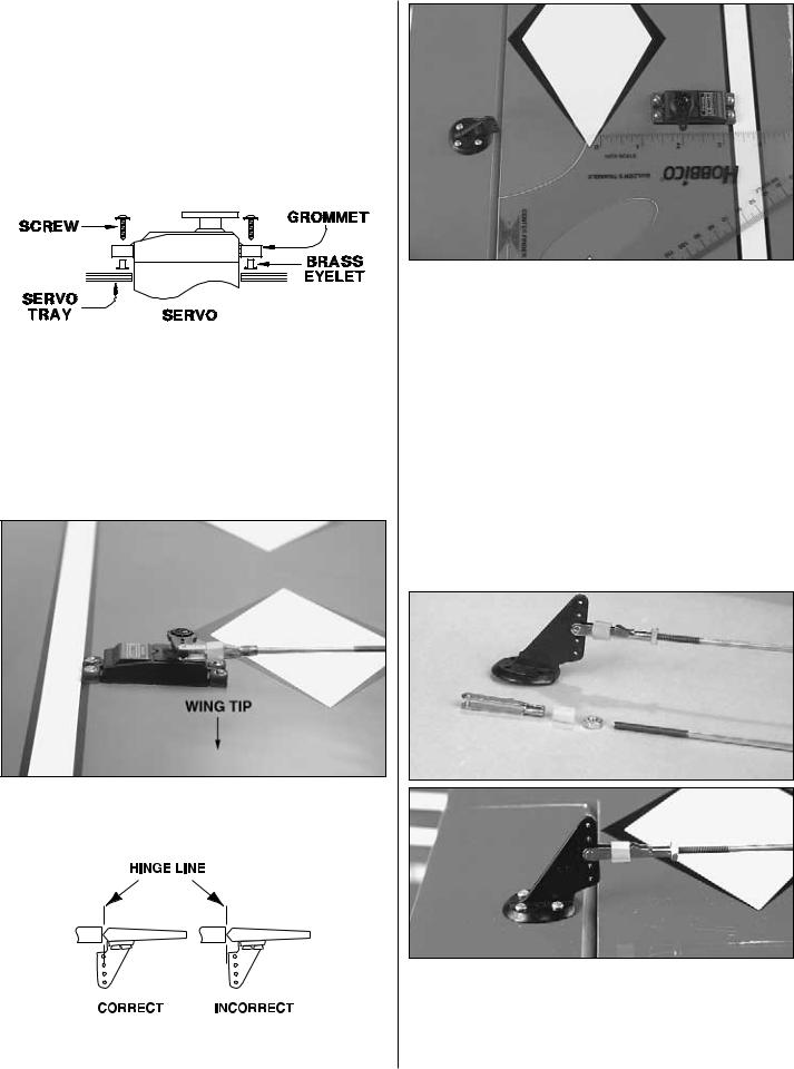
10. Insert the grommets and brass eyelets into the servo as shown. These are included with the hardware package for the servos. Place the servo into its opening in the wing half and drill 1/16" (1.6mm) holes in the wing for the servo mounting screws (also included in the hardware package). Use the techique shown on page 8 to harden the threads. Mount the aileron servos using the servo mounting screws.
11. The servo arms for the aileron servos are installed so that they point outboard toward the wing tips as shown in the above photograph. This is necessary for proper function.
12. Use a builder's triangle to establish a line to the hole in the servo arm at 90 degrees from the trailing edge of the wing. At this location use a nylon control horn as a pattern to mark and drill the four 5/64" (2 mm) holes 1/2" (13 mm) deep into the bottom of each aileron for mounting the nylon control horns. As shown on page 8, run the #4 sheet metal screws into the wood. Then remove them, creating threads in the wood. Saturate these holes with thin CA, wipe away any residual CA and allow it to fully harden. Mount the aileron control horns to the ailerons with four #4 x 1/2" (13mm) sheet metal screws.
13. Install a metal clevis, a 4-40 hex nut, and a clevis retainer on the 4-40 x 12" (305mm) threaded one end pushrod approximately 15 turns. Remember to use
Great Planes Pro Threadlocker (GPMR6060) on these clevises and hex nuts after the radio is set up and control throws have been finished later on in this manual.
10
14.Place the push rod assembly from step 13 on the aileron control horn. Center the servo arm on the servo and align the aileron with the trailing edge of the wing. Place a 4-40 Metal Solder Clevis onto the servo arm and mark the location of the push rod as shown in the sketch above with a felt tip pen. Cut the push rod off at this point and solder the clevis into place.
NOTE: In the above step you are asked to perform a soldering task. Please refer to the following tips to make these solder joints as strong as possible:
HOW TO SOLDER
A. Use denatured alcohol or other solvent to remove residual oil from the pushrod.
B. Use coarse sandpaper to thoroughly roughen the end of the pushrod where it is to be soldered.
C. Apply a few drops of soldering flux to the end of the pushrod, then use a soldering iron or a torch to heat it. Coat the end of the pushrod with silver solder (GPMR8070) by touching the solder to it. The heat of the pushrod should melt the solder – not the flame of the torch or soldering iron – thus allowing the solder to flow.
Note: Do not use silver solder for electrical soldering.
D. Join the clevis to the pushrod. Add another drop of flux, then heat and add solder. The same as before, the heat of the parts being soldered should melt the solder, thus allowing it to flow. Allow the joint to cool without disturbing it. Avoid excess blobs, but make certain the joint is thoroughly soldered. The solder should be shiny, not rough. If necessary, heat the joint again and allow to cool slowly without disturbing it.
E. After the joint has solidified but while it is still hot, carefully use a damp cloth to wipe away the excess soldering flux. Important: After the joint cools, coat it with oil to protect it from rusting.
15. Return to step 4 and do the other 3 wing halves.
Join the Bottom Wing
1. Locate the six die-cut ply wing joiners for the bottom wing. Note that there are two different sizes of wing joiners for the front and back of the bottom wing.
2. Use epoxy to glue the joiners together to form two plywood joiners as shown.
3. After the epoxy has cured, sand off any excess glue and test fit the two lower wing joiners into the two wing halves as shown above. Note that the two 3/8" (9.5mm) wood dowels will be placed into the front of the wing. Test fit them into the wing at this time also. Make sure the wing halves fit together properly and form a good fitting joint. If the wing does not fit properly, carefully sand the tips of the wing joiners until you get the proper fit.
Note: The wing joiners are not designed to fit as tightly as possible in order to allow epoxy to flow around the joiners for a more secure and stronger joint.
11
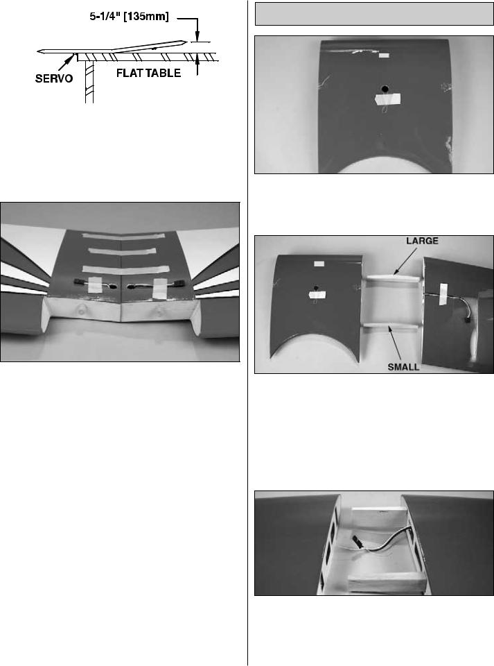
After properly fitting the wing halves together check for the correct dihedral angle. Place one wing panel on a flat surface and measure the distance from the elevated wing tip to the tabletop. This distance should be 5-1/4" (135 mm). Note: You will need to hang the aileron servo off the edge of the table in order to get the wing flat on the table as shown in the sketch above.
4. When satisfied with the fit and the dihedral angle, use 30-minute epoxy to thoroughly coat the root rib of both wing halves and the wing joiners. Be sure to apply a generous amount of epoxy into the inside of each of the wing joiner pockets. Important: Make sure the joiners are fitted upright to ensure the proper dihedral. Then, join the wing halves, holding them together tightly. Use a paper towel, dampened with alcohol, to wipe away excess epoxy that comes out of the joint. Securely hold the wing together with masking tape, making certain both halves are in full contact and that the leading and trailing edges align. Using the same 30-minute epoxy, coat the holes in the front of the wing and the ends of the two 3/8" (9.5mm) wood dowels. Then, insert them into the front of the wing assembly as shown, leaving 1/2" (13mm) of the dowel extending from the wing. You can use rubbing alcohol for any epoxy clean up. Do not disturb the wing until the epoxy has fully hardened.
Join the Top Wing
1. If you haven't already, cut the covering away from the hole in bottom of the top wing center section and feed the string, which is taped to the sheeting, through the hole in bottom of the top wing center section. Retape it securely near the hole.
2. Locate two of the four shaped joiners and test fit the left wing half and the center section together with the two shaped joiners in place. Note that you will be using the large joiner in the front of the wing and the smaller one in the rear of the wing. Notice the placement of the angles of these joiners that allows the wing to taper back from the center section (when positioned properly). Should the fit not be correct, carefully sand the ends of the joiners to allow a proper fit. The top wing has no dihedral and is totally flat.
3. When satisfied with the fit, glue the joiners into the left wing panel using 30-minute epoxy. Place a generous amount of epoxy into the inside of the pockets and on the half of the joiners that will be inserted into the wing pockets. When the epoxy has cured, tie the string in the center section to the aileron servo extension wire as shown in the photo above.
12
 Loading...