


P-51D MUSTANG
.40 Size
INSTRUCTION MANUAL
WARRANTY
Great Planes Model Manufacturing Co guarantees this kit to be free from defects in both material and workmanship at the date of purchase This warranty does not cover any component parts damaged by use or modification In no case shall Great Planes' liability exceed the original cost of the purchased kit. Further, Great Planes reserves the right to change or modify this warranty without notice
In that Great Planes has no control over the final assembly or material used for final assembly no liability shall be assumed nor accepted for any damage resulting from the use by the user of the final user-assembled product By the act of using the user-assembled product, the user accepts all resulting liability
If the buyers are not prepared to accept the liability associated with the use of this product, they are advised to return this kit immediately in new and unused condition to the place of purchase.
|
|
PO Box 788 Urbana IL 61801 (217) 398 8970 |
P540P03forGPMA0175V11 |
PrintedInUSA |
productsupport@greatplanes .com |
Entire Contents © Copyright 2001 |
TABLE OF CONTENTS
INTRODUCTION .............. |
3 |
|
Precautions ................... |
3 |
|
Decisions You Must Make Now ... |
4 |
|
Other Items Required ........... |
|
5 |
Supplies and Tools Needed ....... |
|
5 |
Abbreviations ................. |
5 |
|
Types of Wood ................ |
5 |
|
Get Ready to Build ............. |
|
5 |
Die Patterns .................. |
6 |
|
TAIL FEATHERS ............. |
. |
7 |
Build the Fin and Rudder ........ |
|
7 |
Build the Stabilizer and Elevators .. |
8 |
|
Temporarily Install the Hinges |
.... |
9 |
WING ASSEMBLY ............ |
. |
9 |
Build the Wing Panels . . . . . . |
. . . . |
10 |
Join the Wing Panels ........... |
|
15 |
Install Aileron Torque Rods ...... |
|
16 |
Sand Flat on TE '............... |
|
16 |
Fiberglass the Center Section |
..... |
16 |
Install Wing Tips .............. |
|
17 |
Install Ailerons ................ |
18 |
|
Temporarily Install Wing Dowels .. |
18 |
|
Install Wing Bolt Plate .......... |
|
19 |
Fill LG Slots .................. |
19 |
|
Install Landing Gear Covers ...... |
|
19 |
Install Retracts ................ |
20 |
|
FUSELAGE ASSEMBLY ........ |
|
21 |
Prepare Fuse Sides ............. |
21 |
|
Prepare the Firewall ............ |
|
22 |
Assemble Lower Fuselage ....... |
|
23 |
Drill Engine Mount ............ |
|
26 |
Install Pushrod Guide Tubes ...... |
|
26 |
Mount Wing to Fuse ............ |
|
27 |
Fit Fuel Tank and Fuelproofing |
.... |
29 |
Assemble Aft Deck ............. |
|
30 |
Assemble Front Deck ........... |
|
31 |
Assemble Upper Cowl .......... |
33 |
FINAL ASSEMBLY ............ |
. 34 |
Install Front Wing Fairing ........ |
34 |
Assemble Air Scoop Front ....... |
34 |
Install Wing Fillets ............. |
35 |
Mount Stab and Fin ............. |
36 |
Shaping and Sanding ............ |
37 |
Install Pushrods and Radio ....... |
37 |
Control Surface Throws ......... |
39 |
Install Receiver, etc. ............ 39 |
|
Fit Cowl ..................... |
39 |
FINISHING ................... |
. 40 |
Additional Fuelproofing ......... |
40 |
Balance the Airplane Laterally |
.... 40 |
Final Sanding ................. |
41 |
Covering ..................... |
41 |
Glue the Hinges .............. |
. 41 |
Apply Decals and Trim .......... |
42 |
Install Pilot ................... |
43 |
Glue Canopy in Place ........... |
43 |
Wing Seating .................. |
43 |
Re-install Engine & Radio ....... |
44 |
Balance Your Model ............ |
44 |
Final Hookups and Checks ....... |
44 |
PRE-FLIGHT . . . . . . . . . . . . . . . . |
. . 45 |
Charge the Batteries ............ |
45 |
Find a Safe Place to Fly ......... |
45 |
Ground Check the Model ........ |
45 |
Range Check Your Radio ........ |
45 |
Engine Safety Precautions ........ |
45 |
AMA Safety Code .............. |
. 46 |
FLYING ...................... |
. 46 |
CAUTION . . . . . . . . . . . . . . . . . . . |
. . 47 |
FLIGHT TRIMMING .......... |
. 47 |
PARTS LIST .................. |
. 50 |
3-VIEW . . . . . . . . . . . . . . . . . . . . . |
. . 52 |
2
WARNING! THIS IS NOT A TOY!
THIS IS NOT A BEGINNER'S AIRPLANE!
This R/C kit and the model you will build is not a toy! It is capable of serious bodily harm and property damage. IT IS YOUR RESPONSIBILITY AND YOURS ALONE -- to build this kit correctly, properly install all R/C components and flying gear (engine, tank, pushrods, etc.) and to test the model and fly it only with experienced, competent help, using common sense and in accordance with all safety standards as set down in the Academy of Model Aeronautics Safety Code. It is suggested that you join the AMA and become properly insured before you attempt to fly this model. IF YOU ARE JUST STARTING R/C MODELING, CONSULT YOUR LOCAL HOBBY SHOP OR WRITE TO THE ACADEMY OF MODEL AERONAUTICS TO FIND AN EXPERIENCED INSTRUCTOR IN YOUR AREA.
Academy of Model Aeronautics
5151 East Memorial Drive
Muncie, IN 47302-9252 (800) 435-9262
INTRODUCTION
Congratulations! Thank you for purchasing the Great
Planes P-51D Mustang!
The Great Planes P-51D Mustang is a semi-scale (approximately 1/8-scale) model of the full-size North American P-51D. The prototype as pictured on the box cover is not a copy of any one full-size airplane in particular. Rather, we selected several typical trim features from several aircraft, making a good-looking and rather "generic" trim scheme that typifies the Mustang we all know.
Several full-size P-51 D Mustangs are shown on the box side panel to give you an idea of the many trim variations that have been used. If you are interested in sport scale competition, orjust want to copy a specific full-size trim scheme, you'll be happy to know that color photos of these and MANY other P-51D Mustangs are available from: Scale Model Research, 2334 Ticonderoga Way, Costa Mesa, CA 92626.
Unlike many other scale models, the GreatPlanesP-51D Mustang is easy to build and fly, predictable, highly aerobatic, and has no "bad habits," making it a great sport-scale airplane (as long as you don't get carried away with paint and additions, making it a "lead sled")!. This model is designed to be a great flying "sport airplane," one that you feel comfortable with, flight after flight. It is not intended for scale competition, but with a little extra work it should place well in sport scale competitions at the local level.
This is not a beginner's airplane! While the P-51D is easy to build and flies great, we must discourage you from selecting this kit as your first R/C airplane. It is fast, highly maneuverable, and lacks the self-recovery characteristics of a good basic trainer such as the Great Planes PT Series airplanes. On the other hand, if you have already learned the basics of R/C flying and you are able to safely handle an "aileron trainer" airplane such as the Great Planes Trainer Series or Big Stick Series airplanes, the P-51 D is an excellent choice.
Please inspect all parts carefully before starting to build! If any parts are missing, broken or defective, or if you have any questions about building or flying this airplane, pleasecall usat (217) 398-8970 and we'll be glad to help. If you are calling for replacement parts, please look up the part numbers and the kit identification number (stamped on the end of the carton) and have them ready when calling.
PRECAUTIONS
1.You must build the plane according to the plans and instructions. Do not alter or modify the model, as doing so may result in an unsafe or unflyable model. In a few cases the plans and instructions may differ slightly from the photos. In those instances you should assume the plans and written instructions are correct.
2.You must take time to build straight, true and strong.
3.You must use a proper R/C radio that is in first class condition, the correct sized engine and correct components (fuel tank, wheels, etc.) throughout your building process.
3

4.You must properly install all R/C and other components so that the model operates properly on the ground and in the air.
5.You must test the operation of the model before the first and each successive flight to insure that all equipment is
operating, and you must make certain that the model has remained structurally sound. Be sure to check the nylon clevises often, and replace if they show signs of wear.
6. You must fly the model only with the competent help of a well experienced R/C pilot if you are not already an experienced and knowledgeable R/C pilot at this time.
Note: We, as the kit manufacturer, can provide you with a top quality kit and great instructions, but ultimately the quality and flyability of your finished model depends on how you build it; therefore, we cannot in any way guaranteethe performance ofyourcompletedmodel, and no representations are expressed or implied as to the performance or safety of your completed model.
Remember: Take your time and follow directions to end up with a well-built model that is straight and true.
DECISIONS YOU MUST MAKE NOW
ENGINE AND MOUNT SELECTION
The recommended engine size range is as follows:
.40* - .46 cubic inch displacement 2-cycle
.60** - .70 cubic inch displacement 4-cycle *NOTE: Performance may be marginal if a non-sch- neurle-ported .40 cu.in. 2-Cycle engine is used. **NOTE: The O.S. Max 48 Surpass also provides sufficient power to fly this airplane.
NOTE: If you choose to side mount a 2-Cycle engine, we recommend using a muffler that can be almost completely enclosed inside the cowl. The muffler used in one of our prototypes is a Tatone #11413 Pitts Style Muffler for .29 - .40 engines. The muffler may require slight modification to fit your engine.
If you mount a 2-Cycle engine inverted or upright, a standard muffler may be used. Complete enclosure of the engine and exhaust requires inverted installation and a custom-made exhaust manifold.
The engine you select will determine how you build the fuselage, so it is important that you have the engine close at hand while building.
This kit includes the new Great Planes Adjustable Engine mount. This mount will work on most .40-.60 2-Cycles and .40-.70 4-cycles. Cut or break the "spreader bar" off each mount half. Carefully trim any extra plastic off each mount half left by the spreader bar. The surfaces where the spreader bars were attached need to be very smooth to allow the mount halves to fit together.
Snap the two mount halves together. Slide the mount halves apart until the engine mounting lugs will sit flat on the beams. Adjust the mount until the firewall centerline (or offset line) is centered between the "tick" marks on the mount.
NOTE: If you choose to power your P-51D with a 4- cycle engine, keep in mind that the RPM of your engine will be considerably less than that of a 2-Cycle engine; therefore, you should select a higher pitch propeller to keep the speed and overall performance roughly equivalent to that of a 2-Cycle engine. For example, a 10x6 or 10x7 prop would be used with a .40 (2-Cycle) engine; but a 12x8,11x9 or 10x10 prop may be the best choices for a 4-cycle engine. The 4-blade prop shown on the prototype is a mock-up for static display purposes only.
SELECTION OF WHEELS
To save weight, we recommend using lightweight foam rubber wheels.
2-1/2" diameter main wheels are recommended for retracts (but 2-3/4" wheels will fit, andmay beneeded for satisfactory operation on grass fields).
2-3/4" diameter main wheels arc recommended for normal sport flying with fixed landing gear (3" wheels may be needed for satisfactory operation on rough grass fields).
3-1/4" scale wheels may be installed for maximum scale realism (such as Robart UX-325 diamond-tread scale wheels).
A 1" diameter tailwheel is recommended.
4
OTHER ITEMS REQUIRED |
|
SUPPLIES AND TOOLS NEEDED |
|
0 |
Four-channel radio with 4 servos (additional channel and |
0 |
2 oz. Thin CA Adhesive |
|
retract servo required if retracts are being used). |
0 |
2 oz. Medium or Thick CA Adhesive |
0 |
Propellers (see engine instructions and above engine |
0 |
2.5 oz. 5-Minute Epoxy |
0 |
2.5 oz. 30-Minute Epoxy |
||
|
notes for recommended sizes). |
0 |
Hand or Electric Drill |
0 |
Spinner (2-3/4" diameter) |
0 |
Drill Bits: 1/16", 5/64", 3/32", 7/64", 1/8", 9/64", 5/32", |
|
3/16", 13/64". 7/32", and 1/4" |
||
0 |
Fuel Tank (10 ounce) |
0 |
Sealing Iron |
0 |
5/32" Wheel Collars - 4 |
0 |
Heat Gun |
0 |
3/32" Wheel Collars - 2 |
0 |
Hobby Saw (Xacto Razor Saw) |
0 |
Iron-on Covering Material |
0 |
Xacto Knife, #11 Blades |
0 |
Fuelproof Paint* for Cowl, Canopy, Exhaust Ports & |
0 |
Pliers |
|
Cannons |
0 |
Screw Drivers |
0 |
Silicone Fuel Tubing |
0 |
T-Pins |
0 |
Wing Seating Tape (or silicone sealer ... see instruc- |
0 |
Straightedge |
|
tions) |
0 |
Masking Tape (Required for construction) |
0 |
Latex Foam Rubber Padding (1/4" thick) |
0 |
Sandpaper (coarse, medium, fine grit)* |
0 |
T-Bar Sanding Block (or similar) |
||
0 |
Dubro "E-Z Connector" (optional) |
0 |
Waxed Paper |
0 |
Plastic Pilot: Williams Bros. "Standard, 2" Scale #176" |
0 |
Lightweight Balsa Filler |
|
(WWII Military Style) |
0 |
1/4-20 Tap, Tap Wrench |
0 |
Main Gear Retracts: (optional) |
0 |
Vaseline Petroleum Jelly |
0 |
Isopropyi Rubbing Alcohol (70%) |
||
|
Mechanical:Dave Brown 2-Gear Main, B&D 85- |
0 |
3M "77" Spray Adhesive (optional) |
|
degree mechanical retracts, or equivalent. |
0 |
Dremel Moto Tool or similar (optional) |
|
Pneumatic :Robart #606 85-degree mains, or equiva |
|
|
|
lent (requires #188 air control kit) |
|
*NOTE: On our workbench, we have four 11" T-Bar |
|
|
sanders, equipped with #50, #80, #100 and #150-grit sandpa- |
|
|
*Note: Chevron "Perfect Paint" matches Super Monokote, |
per. This setup is all that is required for almost any sanding |
|
|
task. We also keep some #320-grit wet-or-dry sandpaper |
||
|
and is available in convenient spray cans. |
handy for finish sanding before covering. |
|
COMMON ABBREVIATIONS USED IN THIS BOOK AND ON THE PLANS:
Elev = Elevator
Fuse = Fuselage
LE = Leading Edge (front) LG = Landing Gear
Lt = Left
Ply = Plywood
Rt = Right
Stab = Stabilizer
TE = Trailing Edge (rear) " =Inches
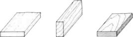
TYPES OF WOOD
B A S S W O O D
GET READY TO BUILD
D |
1. |
Unroll the plan sheets. Re-roll the plans inside out |
to make them lie flat. |
||
D |
2. |
Remove all parts from the box. As you do, figure out |
the name of each pan by comparing it with the plans and the parts list at the back of this book. Using a felt tip pen, write the part name or size on each piece to avoid confusion later. Use the die-cut patterns shown on page 6 to identify the diecutpartsand mark them before punching out. Saveall scraps. If any of the die-cut parts are difficult to punch out, do not force them! Instead, first cut around the pans with an Xacto knife. Afterpunchingoutthe die-cutpans, use yourT-Baror sanding block to lightly sand the edges to remove any diecutting irregularities.
D 3. As you identify and mark the parts, separate them into groups, such as fuse (fuselage), wing. Fin and stab (stabilizer), and hardware.
5

DIE PATTERNS
6
TAIL FEATHERS
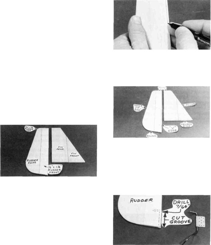
BUILD THE FIN AND RUDDER
To build the fin and rudder you'll need the following: 1/4" shaped balsa fin front
1/4" shaped balsa fin rear 1/4" shaped balsa rudder rear
1/4" x 1-1/4" x 9-1/2" balsa sheet 1/4" x 1/4" x 30" balsa stick
D 1. Tape the fuselage plan down to your flat work surface. Tape a piece of waxed paper over the fin and rudder portion of the plan.
D 2. Working on a flat surface covered with waxed paper, glue the fin front to the fin rear.
D 3. Using a T-bar or sanding block, sand both sides of the fin smooth, then sand the outline of the fin to match the plan.
D 4. Using the plan as a guide, glue the 1/4" x 1-1/4" x 9-1/2" balsa rudder front to the shaped balsa rudder rear, lining up the top edges.
D 5. Cut a 2-1/4" length of 1/4" x 1/4" balsa, and glue it to the top of the rudder.
D 6. Trim the edges of the rudder to match the plan, then use your T-bar with medium grit sandpaper to sand both sides of the rudder smooth.
D 7. Carefully draw a centerline all around the edges of the fin and rudder (this will help to maintain symmetry when sanding).
D 8. Using a sanding block and coarse (50 or 80-grit) sandpaper, sand both sides of the rudder to a taper as shown on the plans. The trailing edge should end up approximately 3/32" wide and have a rounded shape. (Do not sand to a sharp edge). Sand the bottom edge to a rounded shape. Sand the leading edge to a "V-shape" as shown on the plan. Sand the top and front edges of the fin to a rounded shape.
D 9. Check the plans and mark the location of the tailgear* on the rudder. Drill a 7/64" hole in the rudder (the hole is drilled slightly oversize to allow for positioning, and to create a hard epoxy "sleeve" around the wire). Then groove the rudder leading edge to accept the tailgear wire. (See the photo at step 5 on page 18).
7
HINT: Using an Xacto knife, sharpen the inside of one end of a 1/8" diameter brass tube, and use it to cut the groove in the leading edge of the rudder.
*NOTE: The tailwheel location and installation shown on the plan is designed for easy installation and durability. and forthe bestpossible groundhandlingcharacteristics. However, if you are building your P-51 for sport scale competition, you may want to install a tailgear (fixed or retractable) in the "scale location" shown on the plan. These instructions do not cover such a modification, but the location is shown for your convenience.
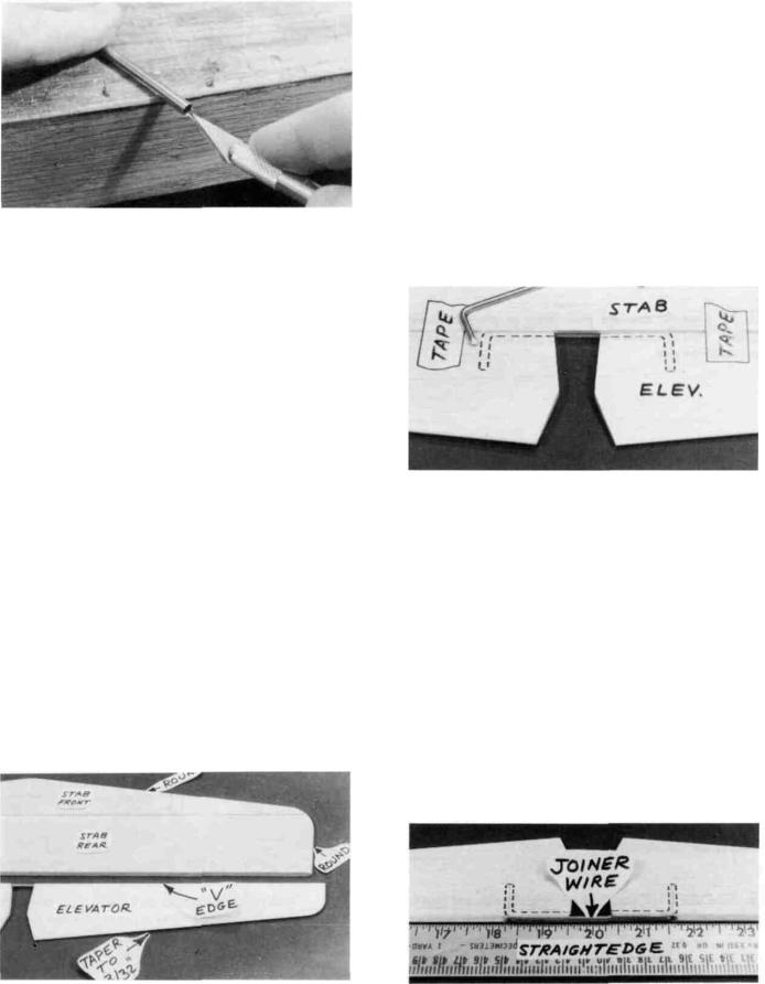
BUILD THE STABILIZER AND
ELEVATORS
To build the stab and elevators you'll need the following: 1/4" shaped balsa stab front
1/4" shaped balsa stab rear 1/4" shaped balsa elevators 1/8" bent wire elevator joiner
D 1. Glue the stab front to the stab rear. Sand the outline of the stab to match the plan, then sand both sides of the stab smooth.
D 2. Sand the leading edge and ends to a rounded shape. (Leave the center portion of the LE square).
D 3. Check the shaped balsa elevators and sand if necessary to match the plan.
D 4. Draw a centerline all around the edges of the stab and elevators.
D 5. Sand both sides of the elevators to a taper as shown on the plans. The trailing edge should end up approximately 3/32" wide and have a rounded shape (do not sand to a sharp edge). Sand the leading edge to a "V-shape" as shown on the plan.
D 6. Temporarily tape the elevators to the stab.
D 7. Lay the 1/8" wire elevator joiner in place on the elevators and mark its outline using a fine point felt-tip pen.
D 8. Accurately drill holes in the elevators for the 1/8" wirejoiner. Begin by drilling a 1/16" or 5/64" pilot hole, then drill the final hole to a depth of 7/8" with a 9/64" drill bit. (The hole is drilled slightly oversize to allow for positioning, and to create a hard epoxy "sleeve" around the wire).
D 9. Using an Xacto knife, sharpen the inside of one end of a 1/8" diameter brass tube and use it to cut grooves in the leading edge of the elevators to accept the joiner wire.
D 10. Roughen thejoiner wire with coarse sandpaper, then clean the wire thoroughly with alcohol to remove any oily residue.
D 11. Trial fit the joiner wire into the elevators, then glue it in using 5-minute or 30-minute epoxy. Work plenty of
8
epoxy into the holes with a toothpick, then lay the elevator leading edges along a straightedge to insure perfect alignment.
TEMPORARILY INSTALL HINGES
(Do not glue)
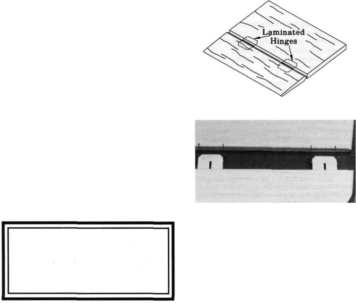
NOTE: On an experimental basis, we have included "laminated hinges" in this kit, and the following instructions are written for this type of hinge. Our R&D department has thoroughly tested these hinges and found them to be easy to install and sufficiently strong and durable for this type of airplane. However, as the kit builder you arc reminded that you are ultimately responsible for the structural integrity of your aircraft. If you are not confident using this type of hinge, please feel free to substitute your favorite hinge.
D 1. Lay the rudder and elevators on the plan and mark the hinge locations. Place the rudder against the fin TE and transfer the marks over to the fin. Place the elevators against the stab TE and transfer the marks over to the stab.
CAUTION!!!: You must use extreme care when cutting hinge slots with an Xacto knife, to avoid cutting yourself! If the balsa part breaks while you are pushing on the knife, the blade could go into your hand before you know it! A good precaution is to wear leather gloves while performing the followingsteps.
D 2. Cut the hinge slots on the accurate centerlines which you previously drew, using an Xacto knife. The recommended procedure for cutting hinge slots with an Xacto knife is given below.
A.Begin by carefully cutting a very shallow slit in the trailing edge at the hinge location. This first cut is to establish your cut in the right place, so concentrate on staying on the centerline and don't cut too deep!
B.Make three or four more cuts in the same line, going slightly deeper each time. As you make these additional cuts, work on going straight into the wood. Con-
tinue this process while ''wiggling" the knife handle back and forth until the blade has reached the proper depth for the hinge.
C. Trial fit the hinge into the slot. If the hinge is difficult to push in, re-insert the knife and move it back and forth in the slot a few times to enlarge the slot.
D 3. Insert the hinges into the slots and trial fit the rudder and elevators in place on the fin and stab. Do not glue the hinges until you are instructed to do so later in this book. Hinge gluing instructions are included later.
WING
NOTE: The following instructions explain how to build the wing on a flat surface, directly on the plans. An alternate method is to use a Great Planes Wing Jig (available from your local hobby dealer). Many expert modelers prefer to use a wing jig for high performance airplanes, as it helps to insure a straight, warp-free wing, especially if you do not have a workbench or building board that is perfectly flat. If you choose to use the Wing Jig, please read the instructions that are included with the jig before beginning.
9
NOTE: Ifyou will be installing a retractable landing gear, disregard Step 6.
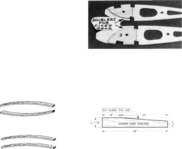
D 6. Note that the wing plan shows the location of the main landing gear blocks. Note also that Ribs W-3 and W-4 have partial cutouts for the grooved landing gear block. If you are building your plane with a fixed (not retractable) landing gear, finish cutting out the notches in these ribs. (If you will be installing retracts, do not cut out these notches).
D 7. Glue the die-cut 1/16" ply notched landing gear doublers to ribs W-3 and W-4 (for fixed gear only). If installing retracts, you will later glue the other set of 1/16" ply "nose rib doublers" to ribs W-4 and W-5. Be sure to glue them to the correct side of the ribs, as shown on the plan (make a right and a left set). Sand the doublers even with the edge of the ribs.
D 8. Prepare the leading edge sheeting by trimming the 3/32" x 2-7/8" x 28" balsa sheets as shown in the following sketch.
NOTE: Follow steps 9 through 36 to build the RIGHT wing panel, then repeat these steps to build the LEFT wing panel.
D D 9. Pin one of the spars |
to the plan with the spar |
doubler up and toward the root. |
NOTE: The spars are cut |
10
slightly too long. Center the spar on the plan so an equal amount protrudes on both ends.
D D 10. Place the ribs on the spar in their approximate position, but do not glue. NOTE: Make sure ribs W-3 and W-4 are installed with the LG notches down, and W-l is installed with the servo opening pointing up.
D D 11. Examine the shaped, notched balsa trailing edges. Notice that the notches at one and of each TE are only 1-7/8" apart. These are the notches for W-1 and W-2. Also notice that all notches in the TE are vertical; however, rib W-l will be installed at a slight angle using the Dihedral Gauge. Therefore, you should now modify the notch for W-l by cutting it to the angle of the rib. You may determine the approximate angle of the cut by holding the Dihedral Gauge (DG) against the TE as shown above.
D D 12. Examine the shaped, notched balsa leading edges. Notice that one end does not have notches, this is the root end. Use a razor saw to cut notches in the leading edge as shown in the "Leading Edge Detail" on the wing plan. These notches will aid in "breaking" the leading edge in the correct locations.
D D 13. Insert the rear ends of the ribs into the notches in the TE, then block up the TE with the 1/4" balsa TE Jig
supplied. NOTE: The narrow end of the TE jig is at rib W-ll. Pin the jig to the building surface.
D D 14. Pin the TE to the TE Jig, making sure the ribs line up with the plan.
D D 15. Glue ribs W-2 through W-ll to the TE. (Apply glue sparingly, to avoid gluing the TE to the TE Jig).
D D 16. Bend (break) the leading edge at the notches which you previously cut, then insertthe frontends ofthe ribs into the notches in the LE. NOTE: Position theLE as shown
here CENTER L.E. VERTICALLY
ON FRONT OF RIBS
D D 17. Make sure the ribs are fully down on the plan and ribs 5 -11 are inserted into the LE notches. Glue ribs 2-11
to the LE and bottom spar. Angle rib W-l slightly using the dihedral gauge (DG). Glue W-l to the TE, LE and bottom spar. NOTE: Thin CA glue may be used in tight-fitting joints, but to insure strong joints we recommend that you follow up by also applying medium or thick CA to all joints.
11
D D 18. Glue the top spar in place (with the spar doubler facing down), making sure you do not change the angle of W-l.
IMPORTANT: In the following steps you'll find it necessary to remove some of the pins holding the wing down to your building board. As you do, take other steps as necessary to continue holding the wing down. such as by applying weight to the top of the wing, or by relocating the pins.
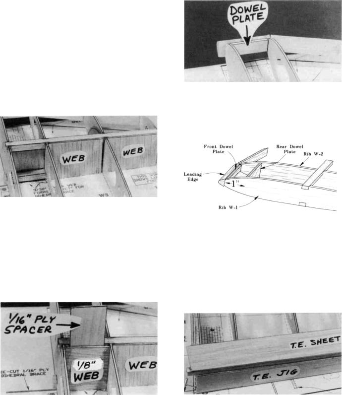
D D 19. Glue the pre-cut 3/32" balsa vertical grain shear webs to the rear edge of the spars in all rib bays except between ribs W-l and W-2. Also install webs on the front of the spars between ribs 1 and 4. NOTE: You may wish to trial fit, mark, and trim each web before gluing in. NOTE: The webs must be securely glued to the spars, but it is not necessary to glue the webs to the ribs.
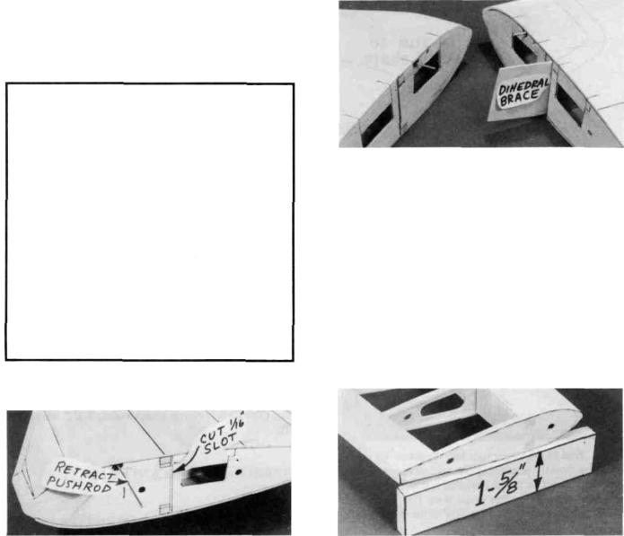
D D 20. You will now make a "pocket" for the 1/16" ply dihedral brace by installing a 1/8" die-cut balsa (horizontal grain) web 1/16" behind the spars. The die-cut web is very close to the correct size, but sand it as necessary for a good fit between W-l and W-2. Using a scrap of 1/16" ply as a temporary spacer, glue the 1/8" web to W-l and W-2.
D D 21. Securely glue the die-cut 1/8" ply dowel plates into the wing. The small dowel plate glues to the back edge ofthe leading edge and to ribs W-l and W-2. The large dowel plate is located 1" behind the small dowel plate, and is glued to ribs W-l and W-2. NOTE: The photo shows only the small dowel plate.
NOTE: In the next steps, maintain straightness by keeping the wing down on the flat surface and on the TF Jig.
D D 22. Lightly sand the tops of the ribs to blend with the notched trailing edge; then glue one of the 3/32" x 1-3/8" x 28" balsa trailing edge sheets in place. NOTE: The edge of the TE sheet may not be exactly straight, butjust position the sheet so it slightly overlaps the TE, and any overlap can be sanded off later.
12

D D 23. Before applying the leading edge sheeting in the next step, use your T-bar to lightly sand off the edges of the shear webs and smoothly blend the ribs to the spar.
D D 24. Prepare the 3/32" balsa leading edge sheeting by sanding the front edge to a slight bevel so it will fit snugly against the back of the leading edge (this is only done in the area from rib W-4 to the tip).
NOTE: It will be helpful to have the following items handy for the next step... thin CA, thick CA, a wet cloth and twelve 8-inch strips of masking tape. Read through the following step and go through a "dry run" before actually gluing.
D D 25. Apply thick CA glue to the top edge of the ribs and to the front half of the spar. Working quickly, position the leading edge sheeting at the rear edge of the notched LE so there is an equal amount protruding on both ends of the wing. Using thin CA, glue the front (beveled) edge of the leading edge sheeting to the back edge of the leading edge. Now wet the top surface of the sheeting so it will bend easier, then immediately bend the sheeting down onto the ribs and spar. Hold the sheeting down with long strips of masking tape until the glue has set.
D D 26. Using four of the 3/32" x 3" x 7-7/8" balsa sheets, cut pieces to complete the LE sheeting from W-1 to W-4, and glue in place. You'll have to wet this sheeting to permit
bending over the ribs. Any small gaps and irregularities may later be sanded or filled with balsa filler.
D D 27. Using the 3/32" x 3" x 7-7/8" balsa sheets and the scraps which you trimmed from the LE sheeting, glue the top center section sheeting in place as shown on the plan.
NOTE: Ifyou are installing retracts, disregard steps 28 through 31.
D D 28. Remove the wing from the building board and trial fit the long grooved hardwood LG block into the notches in ribs W-3 and W-4 (see the landing gear detail drawing on the wing plan for proper positioning). File the notches if necessary for a good fit. Now use epoxy to securely glue the block in place.
13
D D 29. Epoxy the 7/16" x 5/8" x 7/8" hardwood block to the LG block and to the 1/16" ply doubler on rib W-3, as shown on the plan and in the photo, then epoxy the small hardwood gusset to the other end of the LG block and to the 1/16" ply doubler on rib W-4.
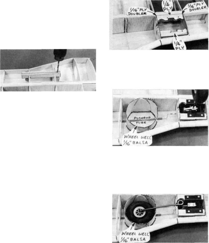
D D 30. Drill a 5/32" hole down through the grooved LG block and the 7/8" block. Line up the drill so you are drilling straight down through the middle of the 7/8" block.
D D 31. Trial fit the 5/32" diameter main landing gear wire into the landing gear block at this time. Cut or file the groove and hole in the landing gear block as necessary for a good fit.
D D 32. Using a razor saw and a sanding block, carefully cut off and sand all excess sheeting, spars, LE and TE even with W-1 and W-11.
NOTE: If you will be installing retracts, now is the time to install the 1/4" x 5/8" x 2-5/8" ply retract mounting rails with epoxy on the bottom of the wing between the 1/16" ply doublers on ribs W-4 and W-5, as shown on the plan. Add 1/4" balsa triangle under the 1/4" ply rails. Installing retracts requires careful planning and a lot of trial Fitting, customizing the installation as necessary to accommodate your retracts; therefore, you should take the time now to plan out your installation. Here are some typical tasks you must perform when installing retracts:
NOTE: All photos in this book show installation of the Dave Brown mechanical retracts.
A.Glue in the 1/16" ply noserib doublers to reinforce ribs W-4 and W-5 where retracts are to be installed.
B.Trial fit the retract unit to determine the mounting location and angles. Cut away the ribs as necessary for
clearance.
C.Gluo in 1/4" ply retract mounting; rails using
epoxy.
D.Trim the rails as necessary.
E.Install pushrod and guide tube just under the top
sheeting.
F.Fabricate wheel well from 1/16** balsa or styro-
foam cup.
G.Install retract unit and check operation.
H.Sheet bottom ofwing, taking note where sheeting will be cut away for retract.
D D 33. With the wing upside down, again use the TE jig to support the TE. Then install the bottom TE sheeting, LE sheeting*andCenterSectionsheeting,cuttingandfittingthe
14
sheeting around the LG block as necessary. IMPORTANT NOTE: To insure a straight wing, you must pin or weight the TE securely down on the TE jig while the bottom sheeting is glued in place!
*As you apply the bottom LE sheeting, remember to mark the sheeting in the exact areas ofthe retract mechanism, LG wire, and wheel well locations, so you can easily find and trim the sheeting from these areas later.
(Retracts): Trim away the sheeting in the area of the retract and wheel well.
NOTE ON RETRACTS: Additional instructions and photos covering installation of retracts will be found at the end of the Wing section, on page 20.
D D 34. From the 3/32" x 1/4" x 30" balsa sticks, cut and glue cap strips to all exposed ribs, top and bottom. HINT: For easier positioning of the cap strips, first mark the location of each rib on the LE and TE sheeting.
D D 35. Trim the sheeting flush with ribs W-l and W-11
and sand the entire wing panel smooth. Sand the leading edge to smoothly blend with the LE sheeting (see note below).
IMPORTANT: The shape of the leading edge will affectthe way this airplane performs snap rolls and spins. A blunt, rounded leading edge will "soften" the stall, making the plane very docile when flying slowly, enabling it to flare nose-high for very slow landings; however, this may cause the plane to be a little sluggish when trying to enter a snap roll orspin. A sharper leading edge will help the plane enter snap roll and spin maneuvers more crisply, while sacrificing only a little of the low speed stability. The leading edge has been approximately pre-shaped, but we recommend that you cut out the Leading Edge Template, and use it as a guide when sanding the leading edge to final shape. To avoid tip stalls, make sure the leading edges of both wing panels have the same shape.
D D 36. Mark and cut out a 1/16" slot in W-l just behind the spars, for the dihedral brace.
D 37. Now go back and repeat Steps 9 through 36 to build the left wing panel.
JOIN THE WING PANELS
NOTE: Read steps 1 through 4, then make a "dry run," practicing these steps before actually proceeding.
D 1. Lay a piece of waxed paper down and place the two wing panels, right side up, so that the W-l ribs are together. Using wood scraps, make two blocks similar to that shown in the photo, and use them toblock up both wing tips 1-5/8 inch. Sand the wing panels at the center so they will fit together without a gap.
D 2. Trial fit the die-cut 1/16" ply dihedral brace to make sure it will readily slide into place.
NOTE: 30-minute epoxy is strongly recommended for the wing joining process.
D 3. Mix up a batch of 30-minute epoxy and push some into the dihedral brace slots. Smear epoxy on the spar ends, and on both sides of the 1/16" ply dihedral brace. Slide the dihedral brace in place, push the wing panels together and immediately proceed to the next step.
D 4. With the wing tips blocked up 1-5/8 inch, carefully align the LE and TE of both wing panels at the center and,
15
while holding them in correct alignment, apply thin CA glue to "lock" the panels together. Do not apply CA glue to any area that is already coated with epoxy. Allow the epoxy to fully harden before disturbing the wing.
D 5. Sand the wing joint smooth all around.
of petroleum jelly to the ends of the plastic tubes (to help prevent glue from getting inside and locking up the torque rods).
D 7. Use 5-minute epoxy or thick CA to glue the plastic bearing tubes into the grooves in the center TE pieces. Wipe off any excess glue and allow it to harden.
INSTALL AILERON TORQUE RODS
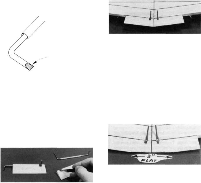
D 1. Roughen the short end of the aileron torque rods with 100-grit sandpaper, and file the same end to a wedge shape,
File end to wedge shape
D 2. Roughen the surface of the plastic bearing tubes with 100-grit sandpaper.
D 3. |
Clean the torque rods and bearing tubes with alco- |
hol. |
|
D 4. Find the two grooved, tapered balsa center trailing edge pieces. Lay them on the plan, mark and cut them off to match the plan for length and angle at the centerline.
D 5. Trial fit the torque rods into the center TE pieces. Determine from the plan where to cut the clearance notches, which will permit the torque rod horns to travel freely. Also cut small clearance notches in the wing TE. Note: The torque rod horns must exit the TOP of the wing!
D 6. Slide the plastic bearings toward the threaded end of the torque rods, then use a toothpick to apply a small amount
D 8. Trial fit the trailing edge / torque rod assemblies onto the wing trailing edge. Sand the center trailing edge pieces slightly where they join, for a good fit. Glue these pieces in place with epoxy. HINT: Use masking tape to hold these pieces to the wing TE, to aid in correct positioning.
SAND "FLAT" ON TE
D 1. Study the wing plan near the wing centerline. Note that the center portion of the TE must be sanded flat.
D 2. Sand approximately 1/4" into the TE at the center-
line. (The flat will end up approximately 3-1/4" wide at the TE).
FIBERGLASS THE CENTER SECTION
NOTE: Because of the high stresses in the center of this wing, fiberglass reinforcement is REQUIRED. Please do not omit this important section!
16
 Loading...