


INSTRUCTION MANUAL
Wingspan: 79-3/4 in [2030mm] Wing Area: 690 sq in [44.5 dm2] Weight: 8.5 – 9 lb [3850 – 4080g]
Wing Loading: 28 – 30 oz/sq ft [85 – 92g/dm2] Length: 52 in [1320mm]
Radio: 5-channel with 7 servos
Engine: .61 – .75 cu in [10 – 12cc] 2-stroke,
.91 cu in [15cc] 4-stroke
WARRANTY
Great Planes® Model Manufacturing Co. guarantees this kit to be free from defects in both material and workmanship at the date of purchase. This warranty does not cover any component parts damaged by use or modification. In no case shall Great Planes’ liability exceed the original cost of the purchased kit. Further, Great Planes reserves the right to change or modify this warranty without notice.
In that Great Planes has no control over the final assembly or material used for final assembly, no liability shall be assumed nor accepted for any damage resulting from the use by the user of the final user-assembled product. By the act of using the user-assembled product, the user accepts all resulting liability.
If the buyer is not prepared to accept the liability associated with the use of this product, the buyer is advised to return this kit immediately in new and unused condition to the place of purchase.
READ THROUGH THIS MANUAL BEFORE STARTING CONSTRUCTION. IT CONTAINS IMPORTANT INSTRUCTIONS AND WARNINGS CONCERNING THE ASSEMBLY AND USE OF THIS MODEL.
1610 Interstate Drive Champaign, IL 61822
(217) 398-8970, Ext. 2 airsupport@greatplanes.com
GPMZ0243 for GPMA1347 V1.0 |
Entire Contents © Copyright 2002 |

TABLE OF CONTENTS |
|
INTRODUCTION ................................................................ |
2 |
IMAA .................................................................................. |
2 |
SAFETY PRECAUTIONS .................................................. |
3 |
DECISIONS YOU MUST MAKE ........................................ |
3 |
Radio Equipment ......................................................... |
3 |
Engine Recommendations........................................... |
4 |
ADDITIONAL ITEMS REQUIRED ..................................... |
4 |
Hardware & Accessories ............................................. |
4 |
Adhesives & Building Supplies .................................... |
4 |
Optional Supplies & Tools............................................ |
4 |
IMPORTANT BUILDING NOTES....................................... |
4 |
COMMON ABBREVIATIONS ............................................ |
5 |
METRIC/INCH RULER ...................................................... |
5 |
ORDERING REPLACEMENT PARTS............................... |
5 |
KIT CONTENTS................................................................. |
6 |
IMPORTANT INSTRUCTIONS ABOUT |
|
WORKING WITH FIBERGLASS ....................................... |
7 |
PREPARATIONS................................................................ |
7 |
BUILD THE WING .............................................................. |
7 |
Install the Flaps & Ailerons .......................................... |
7 |
Install the Flap & Aileron Servo ................................... |
8 |
Install the Flap & Aileron Hardware & Pushrods ....... |
11 |
Join the Wings ........................................................... |
12 |
ASSEMBLE THE FUSELAGE ......................................... |
13 |
Install the Pushrod Tubes & Fuselage Formers......... |
13 |
Install the Horizontal Stab, Elevators, |
|
Rudder & Pushrods ................................................... |
15 |
INSTALL THE ENGINE & MUFFLER.............................. |
17 |
Install the Engine ....................................................... |
17 |
Join the Muffler .......................................................... |
18 |
Install the Nose Wheel............................................... |
19 |
Install the Main Landing Gear.................................... |
23 |
Install the Fuel Tank................................................... |
25 |
INSTALL THE RADIO SYSTEM ...................................... |
25 |
Install the Receiver & Battery .................................... |
28 |
Receiver Antenna Routing......................................... |
28 |
INSTALL THE COWL....................................................... |
29 |
GET THE MODEL READY TO FLY.................................. |
30 |
Check the Control Directions ..................................... |
30 |
Set the Control Throws .............................................. |
30 |
Balance the Model (C.G.) .......................................... |
31 |
Balance the Model Laterally ...................................... |
32 |
PREFLIGHT ..................................................................... |
32 |
Identify Your Model..................................................... |
32 |
Charge the Batteries.................................................. |
32 |
Balance the Propellers............................................... |
32 |
Ground Check............................................................ |
32 |
Range Check ............................................................. |
32 |
ENGINE SAFETY PRECAUTIONS ................................. |
33 |
AMA SAFETY CODE (excerpt) ...................................... |
33 |
IMAA SAFETY CODE (excerpt) ..................................... |
33 |
CHECK LIST.................................................................... |
35 |
FLYING............................................................................. |
35 |
Fuel Mixture Adjustments .......................................... |
35 |
Takeoff ....................................................................... |
36 |
Flight .......................................................................... |
36 |
Landing ...................................................................... |
36 |
ENGINE MOUNT TEMPLATE.......................................... |
39 |
INTRODUCTION
Of the many airplanes flying today, the Lancair (Lance-air) is considered by many to be a “Modern Classic.” With its sleek, clean lines, it has a very graceful appearance both on the ground and in the air. Great Planes is proud to bring you this wonderful classic in an easy to fly model that will impress you by the way it flies and its good looks in the air. We are sure you will get years of enjoyment from your Lancair.
For the latest technical updates or manual corrections to the Lancair, visit the web site listed below and select the Great Planes Lancair ARF. If there is new technical information or changes to this model, a “tech notice” box will appear in the upper left corner of the page.
http://www.greatplanes.com/airplanes/index.html
For information on the full-size Lancair visit this web site:
http://www.lancair.com
IMAA
The Great Planes Lancair is an excellent sport-scale model and is eligible to fly in IMAA events. The IMAA (International Miniature Aircraft Association) is an organization that promotes non-competitive flying of giant-scale models. If you plan to attend an IMAA event, contact the IMAA for a copy of the IMAA Safety Code at the address or telephone number below.
IMAA
205 S. Hilldale Road
Salina, KS 67401 (913) 823-5569
www.fly-imaa.org/imaa/sanction.html
Scale Competition
Though the Great Planes Lancair is an ARF and may not have the same level of detail as an “all-out” scratch-built competition model, it is a scale model nonetheless and is therefore eligible to compete in the Fun Scale class in AMA competition (we receive many favorable reports of Great Planes ARFs in scale competition!) In Fun Scale, the “builder of the model” rule does not apply. To receive the five points for scale documentation, the only proof required that a full-size aircraft of this type in this paint/markings scheme did exist is a single sheet such as a kit box cover from a plastic model, a photo, or a profile painting, etc. If the photo is in black and white, other written documentation of color must be provided. Contact the AMA for a rule book with full details.
2
If you would like photos of the full-size Lancair for scale documentation, or if you would like to study the photos to add more scale details, photo packs are available from:
Bob’s Aircraft Documentation
3114 Yukon Ave
Costa Mesa, CA 92626
Telephone: (714) 979-8058
Fax: (714) 979-7279 e-mail: www.bobsairdoc.com
PROTECT YOUR MODEL, YOURSELF & OTHERS...FOLLOW THESE IMPORTANT SAFETY PRECAUTIONS
1.Your Lancair should not be considered a toy, but rather a sophisticated, working model that functions very much like a full-size airplane. Because of its performance capabilities, the Lancair, if not assembled and operated correctly, could possibly cause injury to yourself or spectators and damage to property.
2.You must assemble the model according to the instructions. Do not alter or modify the model, as doing so may result in an unsafe or unflyable model. In a few cases the instructions may differ slightly from the photos. In those instances the written instructions should be considered as correct.
3.You must take time to build straight, true and strong.
4.You must use an R/C radio system that is in first-class condition, and a correctly sized engine and components (fuel tank, wheels, etc.) throughout the building process.
5.You must correctly install all R/C and other components so that the model operates correctly on the ground and in the air.
6.You must check the operation of the model before every flight to insure that all equipment is operating and that the model has remained structurally sound. Be sure to check clevises or other connectors often and replace them if they show any signs of wear or fatigue.
7.If you are not already an experienced R/C pilot, you should fly the model only with the help of a competent, experienced R/C pilot.
8.While this kit has been flight tested to exceed normal use, if the plane will be used for extremely high stress flying, such as racing, the modeler is responsible for taking steps to reinforce the high stress points.
We, as the kit manufacturer, provide you with a top quality kit and instructions, but ultimately the quality and flyability of your finished model depends on how you build it; therefore, we cannot in any way guarantee the performance of your completed model, and no representations are expressed or implied as to the performance or safety of your completed model.
Remember: Take your time and follow the instructions to end up with a well-built model that is straight and true.
If you have not flown this type of model before, we recommend that you get the assistance of an experienced pilot in your R/C club for your first flights. If you’re not a member of a club, your local hobby shop has information about clubs in your area whose membership includes experienced pilots.
In addition to joining an R/C club, we strongly recommend you join the AMA (Academy of Model Aeronautics). AMA membership is required to fly at AMA sanctioned clubs. There are over 2,500 AMA chartered clubs across the country. Among other benefits, the AMA provides insurance to its members who fly at sanctioned sites and events. Additionally, training programs and instructors are available at AMA club sites to help you get started the right way. Contact the AMA at the address or toll-free phone number below:
Academy of Model Aeronautics
5151 East Memorial Drive
Muncie, IN 47302
Tele: (800) 435-9262
Fax (765) 741-0057 Or via the Internet at:
http://www.modelaircraft.org
DECISIONS YOU MUST MAKE
This is a partial list of items required to finish the Lancair that may require planning or decision making before starting to build. Order numbers are provided in parentheses.
Radio Equipment
The Lancair requires a minimum of a 5-channel radio and receiver, plus: seven servos producing a minimum of 41oz.- in of torque, two Y-harness connectors, two 24" [610mm] and two 12" [305mm] servo extensions.
3
Engine Recommendations
The recommended engine size range for the Lancair is
.61 – .75 cu in [10 – 12cc] two-stroke, .91 cu in [15cc] fourstroke. We flew our prototype with the O.S.® .61 FX (OSMG0561). We found this to be more than adequate power. This coupled with the Top Flite® In-Cowl muffler (TOPQ7917), exhaust header (TOPQ7920), and exhaust deflector (HCAP2180) not only provided the correct power combination but also makes for a very nice scale engine installation. If an engine in the upper end of the size range is used, remember that this is a scale model that is intended to fly at scale-like speeds, so throttle management should be practiced.
In addition to the items listed in the “Decisions You Must Make” section, the following is a list of hardware and accessories required to finish the Lancair. Order numbers are provided in parentheses.
ADDITIONAL ITEMS REQUIRED
Hardware & Accessories
Engine and suitable propellers
Exhaust deflector (HCAP2180)
(2) 12" [300mm] Servo extension (HCAM2711 for Futaba® )
(2) 24" [610mm] Servo extension (HCAM2721 for Futaba)
(2) Y-harness (HCAM2751 for Futaba)
R/C foam rubber (1/4" [6mm] – HCAQ1000, or 1/2" [13mm] – HCAQ1050)
#64 Rubber bands (1/4 lb [113g] box, HCAQ2020)
Adhesives & Building Supplies
In addition to common household tools and hobby tools, this is the “short list” of the most important items required to build the Lancair. Great Planes Pro™ CA and Epoxy glue are recommended.
1/2 oz. [15g] Thin Pro CA (GPMR6001)
1 oz. [30g] Medium Pro CA+ (GPMR6008)
Pro 30-minute epoxy (GPMR6047)
Pro 6-minute epoxy (GPMR6045)
Microballoon filler (TOPR1090)
Optional Supplies & Tools
Here is a list of optional tools mentioned in the manual that will help you build the Lancair.
Drill bits: 1/16" [1.6mm], 5/64" [2mm], 3/32" [2.4mm], 1/8" [3.2mm], 5/32" [4mm], 3/16" [4.8mm], 7/32" [5.6mm], 1/4" [6.4mm]
#11 Blades (5-pack, HCAR0211)
3 Standard silicone tubing (GPMQ4131)
2 oz. [57g] Spray CA activator (GPMR6035)
CA applicator tips (HCAR3780)
CA debonder (GPMR6039)
Epoxy brushes (6, GPMR8060)
Mixing sticks (50, GPMR8055)
Mixing cups (GPMR8056)
36" metal ruler (HCAR0475)
Robart Super Stand II (ROBP1402)
Hobbico® Duster™ can of compressed air (HCAR5500)
Masking tape (TOPR8018)
Threadlocker thread locking cement (GPMR6060)
Rubbing alcohol (for epoxy clean up)
Switch & Charge Jack Mounting Set (GPMM1000)
Rotary tool such as Dremel® Moto-Tool®
Rotary tool reinforced cut-off wheel (GPMR8200)
Servo horn drill (HCAR0698)
Dead Center™ Engine Mount Hole Locator (GPMR8130)
Accu-Throw™ Deflection Gauge (GPMR2405)
CG Machine™ (GPMR2400)
Precision Magnetic Prop Balancer™ (TOPQ5700)
Sealing Iron (TOPR2100)
Sandpaper–100, and 220-grit
6-32 Tap
IMPORTANT BUILDING NOTES
•There are two types of screws used in this kit:
Sheet metal screws are designated by a number and a length. For example #6 x 3/4".
This is a number six screw that is 3/4" long.
Machine screws are designated by a number, threads per inch, and a length. SHCS is just an abbreviation for “socket head cap screw” and that is a machine screw with a socket head. For example 4-40 x 3/4".
This is a number four screw that is 3/4" long with forty threads per inch.
• When you see the term test fit in the instructions, it means that you should first position the part on the assembly without using any glue, then slightly modify or custom fit the part as necessary for the best fit.
4
•Whenever the term glue is written you should rely upon your experience to decide what type of glue to use. When a specific type of adhesive works best for that step, the instructions will make a recommendation.
•Whenever just epoxy is specified you may use either 30-minute (or 45-minute) epoxy or 6-minute epoxy. When 30-minute epoxy is specified it is highly recommended that you use only 30-minute (or 45-minute) epoxy, because you will need the working time and/or the additional strength.
•Photos and sketches are placed before the step they refer to. Frequently you can study photos in following steps to get another view of the same parts.
•The Lancair is factory-covered with Top Flite MonoKote® film. Should repairs ever be required, MonoKote can be patched with additional MonoKote purchased separately. MonoKote is packaged in six-foot rolls, but some hobby shops also sell it by the foot. If only a small piece of MonoKote is needed for a minor patch, perhaps a fellow
modeler would give you some. MonoKote is applied with a model airplane covering iron, but in an emergency a regular iron could be used. A roll of MonoKote includes full instructions for application. Following are the colors used on this model and order numbers for six foot rolls.
White–TOPQ0204, Black–TOPQ0208
Sapphire Blue–TOPQ0226, Metallic Gold–TOPQ0404
COMMON ABBREVIATIONS
Fuse = Fuselage
Stab = Horizontal Stabilizer
Fin = Vertical Fin
LE = Leading Edge
TE = Trailing Edge
LG = Landing Gear
Ply = Plywood
" = Inches
|
|
|
|
|
|
|
|
|
|
|
|
|
|
|
|
|
|
|
|
|
|
|
|
|
|
|
|
|
|
|
|
|
|
|
|
|
|
|
|
|
|
|
|
|
|
|
|
|
|
|
|
|
|
|
|
|
|
|
|
|
|
|
|
|
|
|
|
|
|
|
|
|
|
|
|
|
|
|
|
|
|
|
|
|
|
|
|
|
|
|
|
|
|
|
|
|
|
|
|
|
|
|
|
|
|
|
|
|
|
|
|
|
|
|
|
|
|
|
|
|
|
|
|
|
|
|
|
|
|
|
|
|
|
|
|
|
|
|
|
|
|
|
|
|
|
|
|
|
|
|
|
|
|
|
|
|
|
|
|
|
|
|
|
|
Inch Scale |
|
|
|
|
|
|
|
|
|
|
|
|
|
|
|
To convert inches to millimeters, multiply inches by 25.4 |
|
|
|
|
|
|
|
|
|
|
|
|
|
|
|
|
|
|
|
|
|
|
|
|
|
|
|
|
|
|
|
|||||||||||||||||||||||||||||||||||||||||||||||||||||||||||||||||||||||||||||||||||||||||||||||||||||||||||||||
|
|
|
|
|
|
|
|
|
|
|
|
|
|
|
|
|
|
|
|
|
|
|
|
|
|
|
|
|
|
|
|
|
|
|
|
|
|
|
|
|
|
|
|
|
|
|
|
|
|
|
|
|
|
|
|
|
|
|
|
|
|
|
|
|
|
|
|
|
|
|
|
|
|
|
|
|
|
|
|
|
|
|
|
|
|
|
|
|
|
|
|
|
|
|
|
|
|
|
|
|
|
|
|
|
|
|
|
|
|
|
|
|
|
|
|
|
|
|
|
|
|
|
|
|
|
|
|
|
|
|
|
|
|
|
|
|
|
|
|
||||||||||||||||||||||
0" |
|
|
|
|
|
|
|
|
|
|
|
1" |
|
|
|
|
|
|
|
|
|
|
|
|
|
|
|
2" |
|
|
|
|
|
|
|
|
|
|
|
|
|
|
|
|
|
|
|
3" |
|
|
|
|
|
|
|
|
|
|
|
|
|
|
4" |
|
|
|
|
|
|
|
|
|
|
|
|
|
|
|
|
|
|
5" |
|
|
|
|
|
|
|
|
|
|
|
|
|
|
|
|
|
6" |
|
|
|
|
|
|
|
|
|
|
|
|
|
|
|
|
|
7" |
|
||||||||||||||||||||||||||||||||||||||||||
|
|
|
|
|
|
|
|
|
|
|
|
|
|
|
|
|
|
|
|
|
|
|
|
|
|
|
|
|
|
|
|
|
|
|
|
|
|
|
|
|
|
|
|
|
|
|
|
|
|
|
|
|
|
|
|
|
|
|
|
|
|
|
|
|
|
|
|
|
|
|
|
|
|
|
|
|
|
|
|
|
|
|
|
|
|
|
|
|
|
|
|
|
|
|
|
|
|
|
|
|
|
|
|
|
|
|
|
|
|
|
|
|
|
|
|
|
|
|
|
|
|
|
|
|
|
|
|
|
|
|
|
|
|
|
|
|
|
|
|
|
|
|
|
|
|
|
|
|
|
|
|
|
|
|
|
|
|
|
|
|
|
|
|
|
|
|
|
|
|
|
|
|
|
|
|
|
|
|
|
|
|
|
|
|
|
|
|
|
|
|
|
|
|
|
|
|
|
|
|
|
|
|
|
|
|
|
|
|
|
|
|
|
|
|
|
|
|
|
|
|
|
|
|
|
|
|
|
|
|
|
|
|
|
|
|
|
|
|
|
|
|
|
|
|
|
|
|
|
|
|
|
|
|
|
|
|
|
|
|
|
|
|
|
|
|
|
|
|
|
|
|
|
|
|
|
|
|
|
|
|
|
|
|
|
|
|
|
|
|
|
|
|
|
|
|
|
|
|
|
|
|
|
|
|
|
|
|
|
|
|
|
|
|
|
|
|
|
|
|
|
|
|
|
|
|
|
|
|
|
|
|
|
|
|
|
|
|
|
|
|
|
|
|
|
|
|
|
|
|
|
|
|
|
|
|
|
|
|
|
|
|
|
|
|
|
|
|
|
|
|
|
|
|
|
|
|
|
|
|
|
|
|
|
|
|
|
|
|
|
|
|
|
|
|
|
|
|
|
|
|
|
|
|
|
|
|
|
|
|
|
|
|
|
|
|
|
|
|
|
|
|
|
|
|
|
|
|
|
|
|
|
|
|
|
|
|
|
|
|
|
|
|
|
|
|
|
|
|
|
|
|
|
|
|
|
|
|
|
|
|
|
|
|
|
|
|
|
|
|
|
|
|
|
|
|
|
|
|
|
|
|
|
|
|
|
|
|
|
|
|
|
|
|
|
|
|
|
|
|
|
|
|
|
|
|
|
|
|
|
|
|
|
|
|
|
|
|
|
|
|
|
|
|
|
|
|
|
|
|
|
|
|
|
|
|
|
|
|
|
|
|
|
|
|
|
|
|
|
|
|
|
|
|
|
|
|
|
|
|
|
|
|
|
|
|
|
|
|
|
|
|
|
|
|
|
|
|
|
|
|
|
|
|
|
|
|
|
|
|
|
|
|
|
|
|
|
|
|
|
|
|
|
|
|
|
|
|
|
|
|
|
|
|
|
|
|
|
|
|
|
|
|
|
|
|
|
|
|
|
|
|
|
|
|
|
|
|
|
|
|
|
|
|
|
|
|
|
|
|
|
|
|
|
|
|
|
|
|
|
|
|
|
|
|
|
|
|
|
|
|
|
|
|
|
|
|
|
|
|
|
|
|
|
|
|
|
|
|
|
|
|
|
|
|
|
|
|
|
|
|
|
|
|
|
|
|
|
|
|
|
|
|
|
|
|
|
|
|
|
|
|
|
|
|
|
|
|
|
|
|
|
|
|
|
|
|
|
|
|
|
|
|
|
|
|
|
|
|
|
|
|
|
|
|
|
|
|
|
|
|
|
|
|
|
|
|
|
|
|
|
|
|
|
|
|
|
|
|
|
|
|
|
|
|
|
|
|
|
|
|
|
|
|
|
|
|
|
|
|
|
|
|
|
|
|
|
|
|
|
|
|
|
|
|
|
|
|
|
|
|
|
|
|
|
|
|
|
|
|
|
|
|
|
|
|
|
|
|
|
|
|
|
|
|
|
|
|
|
|
|
|
|
|
|
|
|
|
|
|
|
|
|
|
|
|
|
|
|
|
|
|
|
|
|
|
|
|
|
|
|
|
|
|
|
|
|
|
|
|
|
|
|
|
|
|
|
|
|
|
|
|
|
|
|
|
|
|
|
|
|
|
|
|
|
|
|
|
|
|
|
|
|
|
|
|
|
|
|
|
|
|
|
|
|
|
|
|
|
|
|
|
|
|
|
|
|
|
|
|
|
|
|
|
|
|
|
|
|
|
|
|
|
|
|
|
|
|
|
|
|
|
|
|
|
|
|
|
|
|
|
|
|
|
|
|
|
|
|
|
|
|
|
|
|
|
|
|
|
|
|
|
|
|
|
|
|
|
|
|
|
|
|
|
|
|
|
|
|
|
|
|
|
|
|
|
|
|
|
|
|
|
|
|
|
|
|
|
|
|
|
|
|
|
|
|
|
|
|
|
|
|
|
|
|
|
|
|
|
|
|
|
|
|
|
|
|
|
|
|
|
|
|
|
|
|
|
|
|
|
|
|
|
|
|
|
|
|
|
|
|
|
|
|
|
|
|
|
|
|
|
|
|
|
|
|
|
|
|
|
|
|
|
|
|
|
|
|
|
|
|
|
|
|
|
|
|
|
|
|
|
|
|
|
|
|
|
|
|
|
|
|
|
|
|
|
|
|
|
|
|
|
|
|
|
|
|
|
|
|
|
|
|
|
|
|
|
|
|
|
|
|
|
|
|
|
|
|
|
|
|
|
|
|
|
|
|
|
|
|
|
|
|
|
|
|
|
|
|
|
|
|
|
|
|
|
|
|
|
|
|
|
|
|
|
|
|
|
|
|
|
|
|
|
|
|
|
|
|
|
|
|
|
|
|
|
|
|
|
|
|
|
|
|
|
|
|
|
|
|
|
|
|
|
|
|
|
|
|
|
|
|
|
|
|
|
|
|
|
|
|
|
|
|
|
|
|
|
|
|
|
|
|
|
|
|
|
|
|
|
|
|
|
|
|
|
|
|
|
|
|
|
|
|
|
|
|
|
|
|
|
|
|
|
|
|
|
|
|
|
|
|
|
|
|
|
|
|
|
|
|
|
|
|
|
|
|
|
|
|
|
|
|
|
|
|
|
|
|
|
|
|
|
|
|
|
|
|
|
|
|
|
|
|
|
|
|
|
|
|
|
|
|
|
|
|
|
|
|
|
|
|
|
|
|
|
|
|
|
|
|
|
|
|
|
|
|
|
|
|
|
|
|
|
|
|
|
|
|
|
|
|
|
|
|
|
|
|
|
|
|
|
|
|
|
|
|
|
|
|
|
|
|
|
|
|
|
|
|
|
|
|
|
|
|
|
|
|
|
|
|
|
|
|
|
|
|
|
0 |
10 |
20 |
|
|
|
|
30 |
|
40 |
50 |
|
|
|
|
60 |
70 |
80 |
90 |
|
100 |
|
|
110 |
120 |
130 |
140 |
|
|
150 |
|
160 |
|
|
170 |
180 |
||||||||||||||||||||||||||||||||||||||||||||||||||||||||||||||||||||||||||||||||||||||||||||||||||||||||||||||||||||||||||||||
|
|
|
Metric Scale |
|
|
|
|
|
|
|
|
|
|
|
|
|
|
|
|
|
|
|
|
|
|
|
|
|
|
|
|
|
|
|
|
|
|
|
|
|
|
|
|
|
|
|
|
|
|
|
|
|
|
|
|
|
|
|
|
|
|
|
|
|
|
|
|
|
|
|
|
|
|
|
|
|
|
|
|
|
|
|
|
|
|
|
|
|
|
|
|
|
|
|
|
|
|
|
|
|
|
|
|
|
|
|
|
|
|
|
|
|
|
|
|
|
|
|
|
|
|
|
|
|
|
|
|
|
|
|
|
|
|
|
|
|
|
|
|
|
|||||||||||||||||||||
|
|
|
|
|
|
|
|
|
|
|
|
|
|
|
|
|
|
|
|
|
|
|
|
|
|
|
|
|
|
|
|
|
|
|
|
|
|
|
|
|
|
|
|
|
|
|
|
|
|
|
|
|
|
|
|
|
|
|
|
|
|
|
|
|
|
|
|
|
|
|
|
|
|
|
|
|
|
|
|
|
|
|
|
|
|
|
|
|
|
|
|
|
|
|
|
|
|
|
|
|
|
|
|
|
|
|
|
|
|
|
|
|
|
|
|
|
|
|
|
|
|
|
|
|
|
|
|
|
|
|
|
|
|
|
|
|
|
|
|
|
|
|
|
|
|
|
|
|
|
|
|
|
|
|
|
|
|
|
|
|
|
ORDERING REPLACEMENT PARTS
To order replacement parts for the Great Planes Lancair ARF, use the order numbers in the Replacement Parts List that follows. Replacement parts are available only as listed. Not all parts are available separately (an aileron cannot be purchased separately, but is only available with the wing kit). Replacement parts are not available from Product Support, but can be purchased from hobby shops or mail order/Internet order firms. Hardware items (screws, nuts, bolts) are also available from these outlets. If you need assistance locating a dealer to purchase parts, visit www.greatplanes.com and click on “Where to Buy.” If this kit is missing parts, contact Great Planes Product Support.
|
Replacement Parts List |
|
|
|
Order Number |
Description |
How to Purchase |
|
|
|
Missing pieces............................ |
Contact Product Support |
|
|
|
Instruction manual...................... |
Contact Product Support |
|
|
|
Full-size plans ............................ |
Not available |
|
|
GPMA2320............................................ |
Wing Kit |
|
|
|
GPMA2321............................................ |
Fuse Kit |
|
|
|
GPMA2322 |
Tail Set |
|
Contact Your Hobby |
|
|
|
|||
GPMA2323............................................ |
Cowl ............. |
|
Supplier to Purchase |
|
GPMA2327............................................ |
Canopy |
|
These Items |
|
GPMA2324............................................ |
Landing Gear |
|
|
|
|
|
|
||
GPMA2325............................................ |
Wheel Pants |
|
|
|
GPMA2326............................................ |
Tail Joiner Tube End Rod |
|
|
|
|
|
|
|
|
5
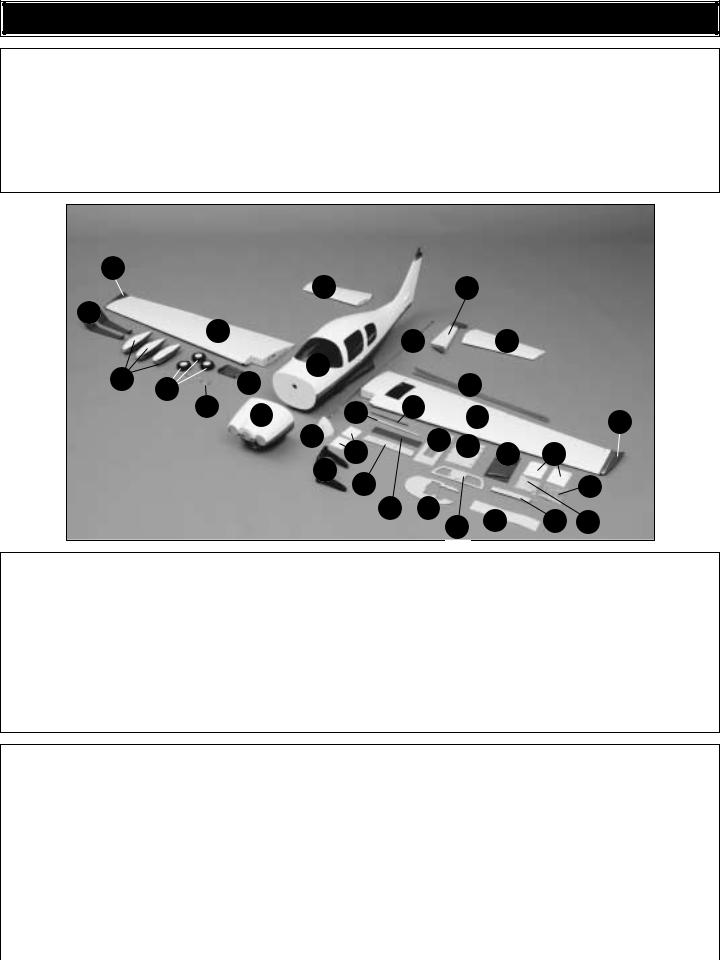
KIT CONTENTS
Before starting to build, use the Kit Contents list to |
an inventory of this kit to make sure it is complete, and inspect the |
parts to make sure they are of acceptable quality. If |
parts are missing or are not of acceptable quality, or if you need |
assistance with assembly, contact Great Planes Product Support. When reporting defective or missing parts, use the part names exactly as they are written in the Kit Contents this page.
Great Planes Product Support:
Telephone: (217) 398-8970
|
|
398-7721 |
E-mail: air |
t@greatplanes.com |
|
|
|
|
8 |
|
|
|
|
|
5 |
6 |
10 |
|
|
|
|
|
3 |
4 |
|
|
15 |
|
9 |
11 |
13 |
32 |
|
|
|
|
|
|
|
8 |
|
|
14 |
|
|
|
20 |
28 |
|
|
16 |
|
|
|
|
31 |
|
|
19 |
|
|
|
|
22 |
Kit Contents (Photographed)
1. |
Fiberglass Fuselage |
12. |
Nose Gear Wire |
23. |
Servo Tray (2) |
2 |
Left Wing/Aileron and Flap |
13. |
Fiberglass Exhaust Air Panel |
24. |
Receiver/Battery Tray (2) |
3. |
Right Wing/Aileron and Flap |
14. |
Spinner |
25. |
Engine Baffle |
4. |
Left Stabilizer |
15. |
Pushrod Wires |
26. |
CA Hinge Strip Material |
5. |
Right Stabilizer |
16. |
Engine Mount |
27. |
Wing Joiner (2) |
6. |
Rudder |
17. |
Carbon Fiber Anti-Rotation Pin |
28. |
Nose Wire Fairing |
7. |
Cowl |
18. |
Aluminum Tube |
29. |
Aileron Covers |
8. |
Fiberglass Wing Tips |
19. |
Wing Bolt Plate |
30. |
Nylon Hardware Bag |
9. |
Fiberglass Wheel Pants |
20. |
Flap Covers |
31. |
Metal Hardware Bag |
10. |
Main Landing Gear |
21. |
Forward Former |
32. |
Outer Pushrod Tubes |
11. |
Wheels |
22. |
Rear Former |
|
|
Kit Contents (Not Photographed)
(4) |
5/16" x 3/4" 7/8" Servo Mount Blocks |
(1) |
Nylon Landing Gear Strap |
(40) |
#2 x 3/8" Sheet Metal Screw |
(2) |
5/32" x 2" Axle |
(1) |
Nylon Retainer For Screw-Lock Pushrod |
(4) |
2-56 x 3/4" Socket Head Cap Screws |
(1) |
Brass Screw-Lock Pushrod Connector |
|
Connector |
(4) |
6-32 x 1" Socket Head Cap Screws |
(2) |
4-40 Blind Nuts |
(1) |
2" x 9" CA Hinge Material |
(4) |
8-32 x 1" Socket Head Cap Screws |
(4) |
8-32 Blind Nuts |
(8) |
Nylon FasLinks |
(4) |
#2 x 1/2" Sheet Metal Screw |
(2) |
5/16-24 Lock Nut |
(8) |
Silicone Clevis Retainer |
(8) |
5/32" Wheel Collar |
(2) |
1/4-20 Blind Nuts |
(1) |
4-40 x 1/8" Socket Head Cap Screws |
(4) |
.074 x 36" Wire Threaded One End |
(3) |
Large Nylon Control Horn |
(4) |
2-56 x 5/8" Machine Screw |
(4) |
.074 x 6" Pushrod Wire |
(4) |
Small Nylon Control Horn |
(8) |
#4 x 1/2" Sheet Metal Screw |
(5) |
#6 Flat Washers |
(1) |
Nose Gear Bearing |
(5) |
6-32 X 1/8" Set Screw |
(22) |
#2 Flat Washers |
(2) |
1/4-20 Nylon Wing Bolt |
(3) |
6-32 x 1/4" Socket Head Cap Screws |
(4) |
#8 Lock Washers |
(1) |
Nylon Steering Control Arm |
(2) |
#4 x 5/8" Sheet Metal Screw |
(4) |
#8 Flat Washers |
(8) |
Nylon Clevis |
(2) |
4-40 x 5/8" Phillips Pan Head Screws |
(4) |
#6 Lock Washers |
|
|
|
|
|
|
|
|
|
|
|
|
|
|
|
6 |
|
|
IMPORTANT INFORMATION ABOUT WORKING WITH FIBERGLASS
If you have never worked with fiberglass there are a few basic things you should be aware of:
•When you are cutting into fiberglass, be sure you are cutting the correct place. Unlike wood, you are not able to go back and easily fix a mistake.
•Whenever you are gluing a part to the inside of fiberglass it is important to roughen the inside surface of the fiberglass with 220-grit sandpaper and then wipe the area with alcohol. The molding process leaves a waxy residue that can prevent a good bond between the glue and the parts being glued.
•If you do not have a high-speed rotary tool such as a Dremel® tool you should consider purchasing one or borrowing one from a fellow modeler. This combined with a fiberglass cut-off wheel is going to be extremely helpful in the assembly process.
WARNING: The cowl, wheel pants and fuselage included in this kit are made of fiberglass, the fibers of which may cause eye, skin and respiratory tract irritation. Never blow into a part to remove fiberglass dust, as the dust will blow back into your eyes. Always wear safety goggles, a particle mask and rubber gloves when grinding, drilling and sanding fiberglass parts. Vacuum the parts and the work area thoroughly after working with fiberglass parts.
PREPARATIONS
1. If you have not done so already, remove the major parts of the kit from the box and inspect for damage. If any parts are damaged or missing, contact Product Support at the address or telephone number listed in the “Kit Contents” section on page 6.
2. Remove the tape and separate the ailerons and flaps from the wing and the elevators from the stab. Use a covering iron with a covering sock on high heat to tighten
the covering if necessary. Apply pressure over sheeted areas to thoroughly bond the covering to the wood.
BUILD THE WING
Install the Flaps & Ailerons
Do the right wing first so your work matches the photos the first time through. You can do one wing at a time, or work on them together.
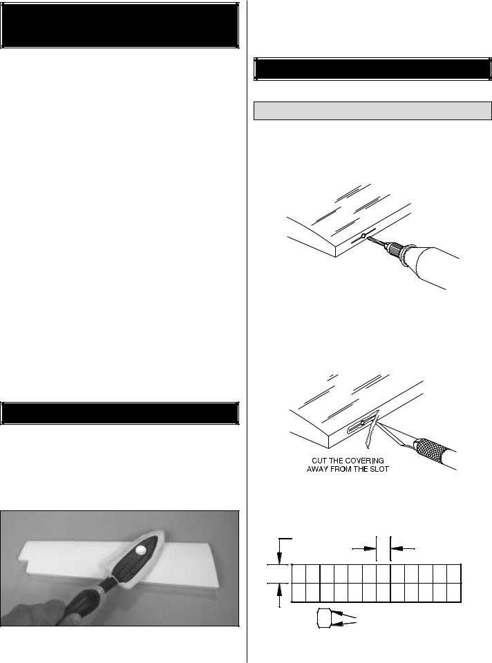
DRILL A 3/32" HOLE 1/2" DEEP, IN CENTER OF HINGE SLOT
1. Drill a 3/32" [2.4mm] hole, 1/2" [12.7mm] deep in the center of each hinge slot to allow the CA to “wick” in. Followup with a #11 blade to clean out the slots. Hint: If you have one, use a high-speed rotary tool to drill the holes.
2. Use a sharp #11 blade to cut a strip of covering from the hinge slots in the wing and aileron.
1" [25mm]
3/4" [19mm]
Trim the Corners
3. Cut seven 3/4" x 1" [19 x 25mm] hinges from the CA hinge strip. Snip off the corners so they go in easier.
7
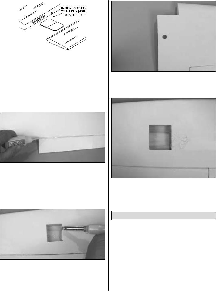
4. Test fit the ailerons to the wing with the hinges. If the hinges don’t remain centered, stick a pin through the middle of the hinge to hold it in position.
5. Remove any pins you may have inserted into the hinges. Adjust the aileron so there is a small gap between the LE of the aileron and the wing. The gap should be small, just enough to see light through or to slip a piece of paper through.
6. Apply six drops of thin CA to the top and bottom of each hinge. Do not use CA accelerator. After the CA has fully hardened, test the hinges by pulling on the aileron.
7. Repeat this procedure for installing the flap using four CA hinges. Note that the hinge slots on the flap are not centered as the ailerons are.
8. Find the hole for the aileron servo by feeling the covering on the bottom of the wing. Cut the covering 1/8" [3mm] inside the opening in the wing for the aileron servo. Use a trim iron to seal the covering to the inner edges of the opening. Repeat this same procedure in the opening for the flap servo.
9. On the top of the wing, cut the covering away from the hole at the wing center-section. This hole is for the aileron and flap servo wires to come through, into the fuselage.
10. Locate the string from inside of the aileron servo bay and tape it to the wing. Do not pull the string out of the wing! Do the same with the string in the flap servo bay.
11. Repeat steps 1-10 for the left wing panel.
Install the Flaps & Aileron Servo
The following steps for installing the servos may be somewhat different from other servo installations you are familiar with. You may find it helpful to read through the servo installation instructions to familiarize yourself with the process before beginning the installation. Important! Following these instructions will assure a safe and solid servo installation.
1. Installing the servos in the wing will require the use of one 24" [610mm] servo extension for the aileron. Depending on your brand of servos you may find it necessary to use one 6" [152mm] servo extension for each of the flaps. Two Y-harness connectors are required and are used to allow the aileron servos to plug into one slot in your
8
receiver and for the flaps to be plugged into another slot in your receiver. You may have a computer radio that allows you to plug the servos into separate slots and then mix them together through the radio transmitter. If you choose to mix them with the radio rather than Y-harnesses, refer to the instructions for your particular brand of radio.
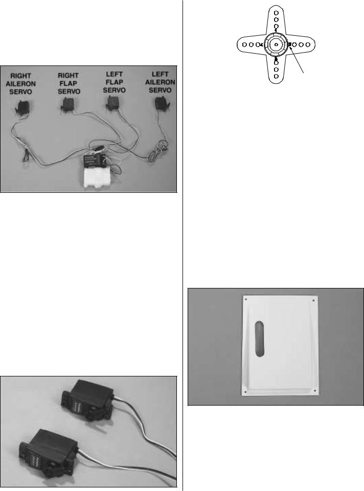
2. Attach the servo extensions to the aileron and flap servos. Secure the connectors together using a large piece of heat shrink tubing, tape or other suitable method. Lay the servos, receiver and battery on your work bench, placing the servos just as they will be when installed in the wing. Remember that you are laying the servos on your bench just as they will be placed into the bottom of the wing. (Note: You will not need to install the rubber grommets and eyelets on the servos for the aileron and flap installation). The servo arms on the flap servos need to move the same direction. The aileron servo arms must move opposite one another. (Note the orientation in the above photograph; remember you are looking at the bottom of the wing).
3. Turn your radio system on, allowing the servos to center. Be sure that all of the radio trims are centered on the transmitter.
4. Using the switch or rotary knob that you will be using to activate the flaps, set the switch to the position that will bring the flaps into the “up” position (normal flying mode). Install the servo arms onto the servo with the arm forward. This will allow the servo to push against the flap control horn to keep the flap retracted. When the flap switch is in the “flaps down” position (landing mode) the arm will rotate in the opposite direction, pulling the flaps down. Operate the servo using the flap switch to be sure they are moving the correct way. Hint: On many brands of servo arms you will find that each arm has a small number on it. Each arm has a slightly different position on the servo spline once it is installed. You will find it helpful for setting up the flaps if you use two arms with the same number on it (see above sketch).
5. Install the servo arms on the aileron servos, making sure the arms are positioned as shown in the photograph in step 2. Using your transmitter, operate the aileron servos making sure that the arms are moving in directions opposite of one another. When you are satisfied everything is working properly, turn off the radio system. Unplug the aileron and flap servos from the receiver.
6. Locate the ABS aileron servo cover for the right wing. Cut out the opening in the cover for the aileron servo arm. The cut lines for the opening are on the inside of the cover. Drill a 1/16" hole [1.6mm] in each corner of the aileron cover.
7. The side of the aileron servo case that will rest against the top of the wing inside of the servo bays needs to be cleaned with rubbing alcohol. Do Not Omit This Step! This surface must be free of any fuel or oil residue in order
9
to assure a good bond between the servo and the servo tape that will be used for holding the servo to the wing.
8. Tie the string inside the aileron servo bay to the aileron servo wire. Pull the servo wire out towards the wing root with the string. Feed the end of the wire through the hole in the top of the wing center-section. Remove the string from the servo lead and tape the servo lead to the top of the wing to prevent it from falling back into the wing.
9. Place the aileron servo into the servo bay. Temporarily place the aileron cover over the servo to help locate the final position for the servo. Remove the cover and make a couple of reference marks inside the servo bay for the servo location. This will help you relocate the servo when it is installed in the next step.
10. Using 6-minute epoxy, permanently glue the servo in place inside the servo bay, gluing it to the wing skin. Note:
We understand that some modelers may resist gluing a servo permanently to the wing. Because of the very thin airfoil it becomes difficult to make a removable servo mounting assembly. Fortunately the servo required for the aileron are the standard, inexpensive type and permanently installing them should not be cost prohibitive. The Expert Tip that follows presents an alternative method of gluing in the servos.
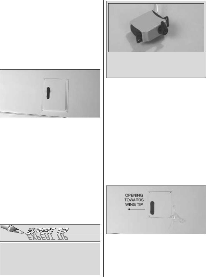
One method for gluing the servo in place while still having the option to remove it is to wrap 2-1/2" [64mm] heat shrink tubing around the servo (PARC1625). This heat shrink is commonly used for making battery packs. After the servo is tightly encapsulated with the heat shrink tubing, glue the servo in place in the wing.
Should you ever need to remove the servo simply cut the heat shrink tubing and remove the servo. If you do not have heat shrink tubing readily available, you can achieve similar results by wrapping the servo with electrical tape and then gluing it in position.
11. Place the aileron servo cover over the servo, making sure the servo arm is centered in the cut out. Using the cover as a guide, drill a 1/16" [1.6mm] hole into the wing skin through each of the holes in the cover. Remove the cover.
12. Thread a #2 x 3/8" [9.5mm] sheet metal screw into each of the four holes. Remove the screw, then saturate the holes with thin CA. Enlarge the holes in the cover only with a 3/32" [2.4mm] drill. Allow the CA to cure and then install the cover into place over the servo.
13. Locate the wood flap servo cover for the right wing. Cut the covering from the opening for the servo in the cover. Temporarily place the cover into position with the slot towards the wing tip. Note: On the left wing, the slot in the cover is towards the wing root. Drill a 1/16" hole [1.6mm] through each corner of the aileron cover and through the hardwood tabs in the wing. Remove the cover. Drill a 3/32" [2.4mm] clearance hole through each of the holes in the servo cover only!
10
14. Drill 1/16" [1.6mm] holes in two 5/16" x 3/4" x 7/8" [7.9 x 19.1 x 22.2mm] servo mount blocks and mount the aileron servo to the blocks using the screws that came with the servo. Glue the servo mount blocks to the inside of the flap servo cover with 6-minute epoxy.
15. After the epoxy has hardened, remove the screws that mount the servos to the blocks. Apply a few drops of thin CA to the holes and allow to harden. Remount the servo to the blocks.
16. Tie the string inside the flap servo bay to the flap servo wire. Pull the servo wire out the root of the wing with the string. Feed the end of the wire through the hole in the top of the wing center-section. Remove the string from the servo wire and tape it to the top of the wing to prevent the servo wire from falling back into the wing.
17. Use four #2 x 3/8" [9.5mm] sheet metal screws and four #2 flat washers to attach the cover to the wing.
18. Repeat steps 1-17 for the left wing panel.
Install the Flap & Aileron Hardware
& Pushrods
1. Position a small nylon control horn on the aileron, positioning it as shown in the sketch and aligning it with the servo. Mark the location for the screw holes. Drill through the marks you made with a 3/32" [2.4mm] drill bit. Mount the nylon control horn to the aileron by inserting two 2-56 x 5/8" [2-56 x 16mm] machine screws through the control horn and into the nylon mounting plate on the top of the aileron.
2. Locate a .074" x 6" [1.9 x 152mm] pushrod wire threaded on one end. Thread a nylon clevis onto the threaded end of the wire 20 turns. Install a silicone clevis retainer onto the clevis. Then, install the clevis on the aileron control horn.
3. Be sure the aileron servo is centered (plug the servo into the receiver and turn the radio on to re-center it properly if you are unsure). Enlarge the hole in the servo arm with a Hobbico Servo Horn Drill (or a #48 or 5/64" [2mm] drill bit). Center the aileron and align the wire pushrod with the hole in the end of the servo arm. Using a marker, mark the location where the wire aligns with the hole in the servo arm. On that mark make a 90° bend. From the bend measure an additional 3/8" [9.5mm] and then cut off the excess pushrod wire.
4. Install the wire into the hole in the servo arm using a nylon FasLink as shown in the sketch.
5. Position a small nylon control horn on the flap, positioning it in the same manner as you did the aileron. Mark
11
the location for the screw holes. Drill through the marks you made with a 1/16" [1.6mm] drill bit, drilling through the plywood plate in the bottom of the flap. Do not drill all the way through the flap. Install the screw, then remove it. Harden the holes with thin CA. Mount the nylon control horn to the flap with two #2 x 3/8" [#2 x 9.5mm] sheet metal screws.
6. Locate a .074" x 6" [1.9 x 152mm] pushrod wire threaded on one end. Thread a nylon clevis onto the threaded end of the wire 20 turns. Install a silicone clevis retainer onto the clevis. Then, install the clevis to the flap control horn.
7. Be sure the flap servo arm is forward, in the position that will pull the flap into the retracted position. (Plug the servo into the receiver and turn the radio on to re-position it properly if you are unsure). Enlarge the hole in the servo arm with a Hobbico Servo Horn Drill (or a #48 or 5/64" [2mm] drill bit). Position the flap to the retracted (neutral) position and align the wire pushrod with the hole in the end of the servo arm. Using a marker, mark the location where the wire aligns with the hole in the servo arm. On that mark make a 90° bend. From the bend measure an additional 3/8" [9.5mm] and then cut off the excess pushrod wire.
8. Install the wire into the hole in the servo arm using a nylon FasLink.
9. Repeat steps 1-8 for the left wing panel.
Join the Wings
1. Locate the two 1/8" [3mm] plywood wing joiners. Using 6-minute epoxy, glue them together, forming one 1/4" [6mm] wing joiner.
2. Test fit the wing joiner into each wing panel, making sure that it is not too tight. Sand the joiner as needed to get a good fit.
3. Apply 30-minute epoxy to both sides of the wing joiner, the joiner pocket in both wing panels and to the root rib of
each wing panel. Push the wing panels together and hold them in place with masking tape. Before the glue cures, set the wing flat on your bench and measure the dihedral. The distance from the top of the bench to the bottom of the wing should be approximately 4-1/8" [105mm]. Block the wing tip up while the glue cures. Note: Due to production techniques there may be some variance in the actual dihedral of each model. Our prototypes flew well with the dihedral anywhere between 3-7/8" and 4-1/4" [98mm and 108mm]. Minor differences will not affect the flight characteristics.
4. Set the wing aside allowing the glue to cure.
5. Locate two 3/8" x 1-3/4" [9.5mm x45mm] wood dowels. Apply 6-minute epoxy to the portion of the dowel that will be inserted into the holes in the leading edge at the center-section of the wing. Apply epoxy into the holes in the center-section of the wing. Then, insert the dowels into the holes until they stop. Wipe away excess glue from the dowels and set the wing aside to dry.
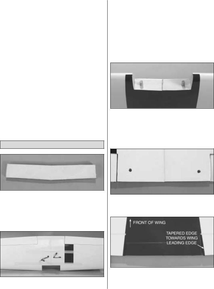
6. Locate the 1/4" [6mm] holes under the covering at the trailing edge of the wing center-section. Cut the covering away on both the top and bottom of the wing.
7. Lay the wing on your bench with the bottom of the wing facing you. Locate the hardwood wing hold down plate. Place the hold down plate in position at the wing trailing edge with the tapered edge of the plate facing the front of
12
 Loading...