


INSTRUCTION MANUAL
WARRANTY
Great Planes® Model Manufacturing Co. guarantees this kit to be free from defects in both material and workmanship at the date of purchase. This warranty does not cover any component parts damaged by use or modification. In no case shall Great Planes’ liability exceed the original cost of the purchased kit. Further, Great Planes reserves the right to change or modify this warranty without notice.
In that Great Planes has no control over the final assembly or material used for final assembly, no liability shall be assumed nor accepted for any damage resulting from the use by the user of the final user-assembled product. By the act of using the user-assembled product, the user accepts all resulting liability.
If the buyer is not prepared to accept the liability associated with the use of this product, the buyer is advised to return this kit immediately in new and unused condition to the place of purchase.
While this kit has been flight tested to exceed normal use, if the plane will be used for extremely high stress flying, the modeler is responsible for taking steps to reinforce the high stress points.
READ THROUGH THIS MANUAL BEFORE STARTING CONSTRUCTION. IT CONTAINS IMPORTANT WARNINGS AND INSTRUCTIONS CONCERNING THE ASSEMBLY AND USE OF THIS MODEL.
P.O. Box 788 |
Urbana, IL 61803 (217) 398-8970 |
© Copyright 2000 |
GPMZ0217 for GPMA1315 V1.0 |
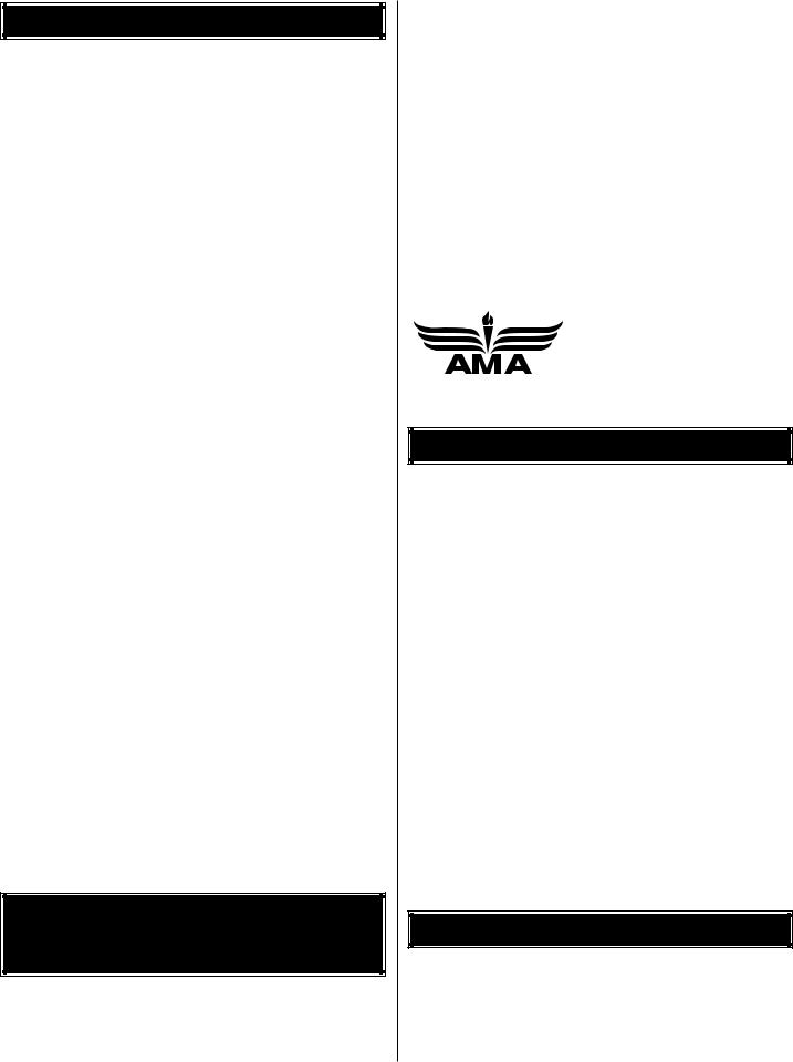
TABLE OF CONTENTS |
|
Important Safety Precaution...................................................... |
2 |
Introduction................................................................................. |
2 |
Precautions ................................................................................. |
2 |
Decisions You Must Make.......................................................... |
3 |
Engine Selection.................................................................... |
3 |
Preparations ................................................................................ |
3 |
Required Accessories............................................................ |
3 |
Building Supplies and Tools .................................................. |
3 |
Optional Supplies and Tools.................................................. |
4 |
General Inspection ................................................................ |
4 |
Inch/Metric Ruler ................................................................... |
4 |
Parts List................................................................................ |
5 |
Wing Assembly ........................................................................... |
6 |
Rudder Assembly .................................................................. |
6 |
Wing Installation ......................................................................... |
7 |
Install The Stabilizer ................................................................... |
7 |
Engine Installation...................................................................... |
8 |
Cowling Installation.................................................................. |
10 |
Fuel Tank Installation ............................................................... |
10 |
Main Landing Gear Installation ............................................... |
11 |
Radio Installation...................................................................... |
12 |
Attach the Ailerons............................................................... |
12 |
Install the Aileron Servos..................................................... |
13 |
Attach the Elevators ............................................................ |
14 |
Install the Elevator Servos................................................... |
15 |
Attach the Rudder................................................................ |
16 |
Install the Rudder Servo...................................................... |
16 |
Tail Gear Installation............................................................ |
17 |
Throttle Servo Installation.................................................... |
18 |
Receiver & Battery Installation ............................................ |
19 |
Final Assembly.......................................................................... |
19 |
Control Throw Adjustment ................................................... |
20 |
Control Surface Throws....................................................... |
20 |
Balance Your Model.................................................................. |
20 |
Balance Your Model Laterally.............................................. |
21 |
Advanced Aerobatics ............................................................... |
21 |
Preflight ..................................................................................... |
23 |
Charge the Batteries ........................................................... |
23 |
Balance the Propeller .......................................................... |
23 |
Find a Safe Place to Fly ...................................................... |
23 |
Ground Check Your Model .................................................. |
23 |
Range Check Your Radio .................................................... |
23 |
Engine Safety Precautions .................................................. |
24 |
AMA Safety Code (excerpt)...................................................... |
24 |
General................................................................................ |
24 |
Radio Control....................................................................... |
24 |
Flying ......................................................................................... |
24 |
Takeoff ................................................................................. |
24 |
Flying ................................................................................... |
25 |
Landing................................................................................ |
25 |
Appendix: Flight Trimming ...................................................... |
26 |
Flight Log .................................................................. |
Back Cover |
Engine Mount Template ........................................... |
Back Cover |
PROTECT YOUR MODEL,YOURSELF & OTHERS...FOLLOW THIS IMPORTANT SAFETY PRECAUTION
Your Giles G-202 ARF is not a toy, but rather a sophisticated, working model that functions very much like a full-size airplane. Because of its realistic performance, the Giles G-202 ARF, if not assembled and operated correctly,
could possibly cause injury to yourself or spectators and damage property.
To make your R/C modeling experience totally enjoyable, we recommend that you get experienced, knowledgeable help from an instructor with assembly and during your first flights. You’ll learn faster and avoid risking your model before you’re truly ready to solo. Your local hobby shop has information about flying clubs in your area whose membership includes qualified instructors.
You can also contact the national Academy of Model Aeronautics (AMA), which has more than 2,500 chartered clubs across the country. Through any one of them, instructor training programs and insured newcomer training are available. Contact the AMA at the address or toll-free phone number below:
Academy of Model Aeronautics
5151 East Memorial Drive
Muncie, IN 47302-9252
Tele. (800) 435-9262


 Fax (765) 741-0057 Or via the internet at: http://www.modelaircraft.org
INTRODUCTION
Congratulations and thank you for purchasing the Great Planes Giles G-202 ARF. We’d like to provide you with a bit of history on our selection of this aircraft as the newest release in the Great Planes scale aerobatic ARF line.
Richard Giles noted a trend in the International Aerobatic Club (I.A.C.) competition arena toward bigger, heavier, more costly “super monoplanes,” and he wanted to do better. The resulting “full-scale” Giles G-200 and G-202 were designed specifically to be a reasonably priced, low wing loading, unlimited level, superior performer on a reasonably priced 4-cylinder engine.
Flying the Giles G-202 is a thrilling experience–as it should be for such an aerobatic model! It doesn’t take much elevator or aileron throw to put the Giles through its paces. When you have a feel for your Giles G-202, the throws can be increased to high rates (illustrated in the instructions) to really showcase the aerobatic potential.
We hope you enjoy building and flying your Great Planes Giles G-202 ARF as much as we did testing the prototypes.
PRECAUTIONS
1.You must assemble the model according to the instructions. Do not alter or modify the model, as doing so may result in an unsafe or unflyable model.
2.Take time to align the components straight, true and strong.
2

3. Use an R/C radio system that is in first-class condition, and a correctly sized engine and components (fuel tank, wheels, etc.) throughout your assembly process.
4. You must properly install the R/C radio system and other components so that the model operates properly on the ground and in the air.
5. You must test the operation of the model before every flight to insure that all equipment is operating and you must make certain that the model has remained structurally sound. Be sure to check clevises and other connectors often and replace them if they show signs of wear or fatigue.
Note: We, as the manufacturer, provide you with a top quality kit and great instructions, but ultimately the quality of your finished model depends on how you assemble it; therefore, we cannot in any way guarantee the performance of your completed model, and no representations are expressed or implied as to the performance or safety of your completed model.
Remember: Take your time and follow directions to end up with a well-built model that is straight and true. Please inspect all parts carefully before starting to build! If any parts are missing, broken or defective, or if you have any questions about assembling or flying this airplane, please call us at (217) 398-8970. If you are calling for replacement parts, please reference the part names and numbers on page 5 and have them ready when calling.
We can also be reached by e-mail at:
productsupport@greatplanes.com
DECISIONS YOU MUST MAKE
Engine Selection
There are several engines that will work well in your Giles G-202 ARF. We recommend a SuperTigre® G-2300 for the best performance for your Giles G-202. An O.S.® FT-160 would be the best choice for a 4-stroke. Your choice of 2-stroke or 4-stroke will determine the location of the throttle servo and throttle pushrod exit on the firewall, so plan ahead.
Note: Please see the FLYING section regarding flutter, propeller selection and aerobatic performance.
PREPARATIONS
Required Accessories
Items in parentheses such as (GPMQ4243) are suggested part numbers recognized by distributors and hobby shops and are listed for your ordering convenience. GPM is the Great Planes brand, TOP is the Top Flite® brand, and HCA is the Hobbico® brand.
Four-Channel Radio with Six Servos (minimum of 65 oz/in of torque for flight controls)
“Y” Harness for Aileron and Elevator Servos (if not using a computer radio)
Five 24" Servo Extensions for Aileron, Elevator and Rudder Servos
Engine - See Engine Selection
Spare Glow Plugs (O.S. #8 for most 2-Stroke engines, OSMG2691, or O.S. Type F for most 4-stroke engines, OSMG2692)
Propeller (Top Flite Power Point®-refer to your engine’s instructions for proper size)
3' Medium 3/32" Glow Fuel Tubing (GPMQ4131)
1/4" Latex Foam Rubber Padding (HCAQ1000)
Building Supplies & Tools
These are the building tools that are required. We recommend Great Planes Pro™ CA and Epoxy glue.
2 oz. Pro CA (Thin, GPMR6003)
2 oz. Pro CA+ (Medium, GPMR6009)
CA Accelerator (GPMR6035)
6-Minute Pro Epoxy (GPMR6045)
30-Minute Pro Epoxy (GPMR6047)
Canopy Glue (JOZR5007)
#1 Hobby Knife Handle (HCAR0105)
#11 Blades (HCAR0311, 100 Qty)
Builders Triangle Set (HCAR0480)
Masking Tape (TOPR8018)
Electric Power Drill
Slip-Joint & Needle Nose Pliers
Monofilament String for Stabilizer Alignment
Screwdrivers – Flat Blade & Phillips
Pro Thread Locking Compound (GPMR6060)
Isopropyl Alcohol (70%)
Drill Bits: 1/16" [1.5mm], 3/32" [2.5mm], 1/8" [3mm], 9/64" [3.5mm], 3/16" [5mm], 7/32" [5.5mm], 1/4" [6mm], 5/16" [8mm], 1/2" [13mm], #29
8-32 Tap & Drill (GPMR8103)
Top Flite Trim Seal Tool™ (TOPR2200)
Panel Line Pen (TOPQ2510)
Sandpaper (coarse and fine grit)
Metal File
3/4 oz. Fiberglass Cloth (HCAR5000)
Paper Towels
T-Pins (HCAR5100)
Silver Solder (GPMR8070)
3

Electrical Tape or Heat Shrink Tubing
Hobby Heat™ Micro Torch (HCAR0750)
Razor Saw
Petroleum Jelly
4" White Spinner
Optional Supplies & Tools
CA Applicator Tips (HCAR3780)
Epoxy Brushes (GPMR8060)
Epoxy Mixing Sticks (GPMR8055, Qty. 50)
CA Debonder (GPMR6039)
Dremel® Moto-Tool™ or Similar with Cut-Off Wheel
Hot Sock™ (TOPR2175)
Dead Center™ Engine Mount Hole Locator (GPMR8130)
Curved Tip Canopy Scissors for Canopy Trimming (HCAR0667)
Switch and Charge Jack (GPMM1000)
Sealing Iron (TOPR2100)
Household Oil
6 oz. Segmented Lead Weight (GPMQ4485)
C.G. Machine™ (GPMR2400)
Power Point® Balancer (TOPQ5700)
Fingertip Prop Balancer (GPMQ5000)
Fueling System (Great Planes Top Fueler™, GPMQ4160)
General Inspection
1.Closely inspect the fuselage, wing panels, rudder assembly and stabilizer assembly for damage. If you find any damage, contact the place of purchase, or Hobby Services at Great Planes for a replacement.
2.Eliminate any wrinkles you find in the covering by shrinking them away with a heat gun, then apply pressure to the area with a covering iron and a hot sock. This will securely bond the covering to the wood so the wrinkles will be less likely to reappear in the future. Caution: Be careful while working around areas where the colors overlap.
Inch Scale
0" |
1" |
2" |
3" |
4" |
5" |
6" |
7" |
0 |
10 |
20 |
30 |
40 |
50 |
60 |
70 |
80 |
90 |
100 |
110 |
120 |
130 |
140 |
150 |
160 |
170 |
180 |
|
Metric Scale |
|
|
|
|
|
|
|
|
|
|
|
|
|
|
|
|
|
4
Parts List
5 |
|
|
3 |
|
12 |
|
|
|
1 |
10 |
11 |
4
2
15
16 |
9 |
14
Key# |
Description |
Qty |
1 |
Fuselage |
1 |
2 |
Left Wing Panel w/Aileron |
1 |
3 |
Right Wing Panel w/Aileron |
1 |
4 |
Cowl |
1 |
5 |
Wing Belly Pan |
1 |
6 |
Canopy |
1 |
7 |
Right Wheel Pant |
1 |
8 |
Left Wheel Pant |
1 |
9 |
Aluminum Landing Gear (Right & Left) |
2 |
10 |
Stabilizer |
1 |
11 |
Elevator Assembly (Right & Left) |
2 |
12 |
Rudder |
1 |
13 |
Wing Dowels |
2 |
14 |
Servo Tray |
1 |
15 |
Wing Joiner |
1 |
16 |
Wing Bolt Plate |
1 |
Parts Not Shown In Photo |
|
|
Description |
Qty |
|
Adjustable Engine Mount (Right & Left Halves) |
2 |
|
Tail Wheel Assembly |
1 |
|
Main Wheels |
2 |
CA Hinge Strip (2" x 9") |
1 |
Hardware Bag |
1 |
Replacement Parts
If needed, replacement parts for Giles G-202 ARF are
available through your hobby supplier. |
|
Wing Set............................................................ |
GPMA2180 |
Fuselage Kit ...................................................... |
GPMA2181 |
Tail Set............................................................... |
GPMA2182 |
Canopy .............................................................. |
GPMA2183 |
Cowl .................................................................. |
GPMA2184 |
Wheel Pants ...................................................... |
GPMA2185 |
Landing Gear Set .............................................. |
GPMA2186 |
5
WING ASSEMBLY
Rudder Assembly
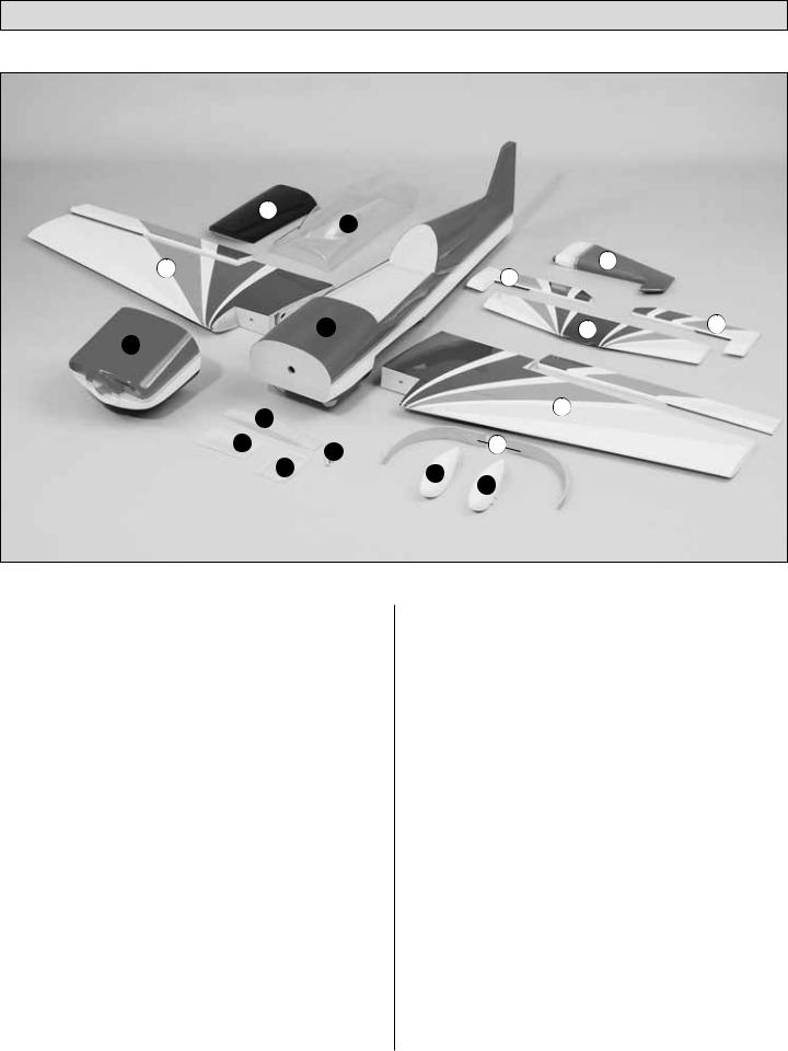
1. Locate the servo cut out on the bottom of each wing and cut the covering 1/8" [3mm] inside the edges of the opening in the bottom of the right wing panel for the aileron servo. Use your Top Flite MonoKote® Trim Seal Tool™ to seal the covering to the sides of the opening.
Note: You’ll notice a piece of string that passes through the ribs at the location of the aileron servo well. Don’t remove the string because you will use it to pull your aileron servo cord through the wing later. Tape the string in place as shown.
2. Locate the hole and cut the covering on the top of the right wing panel for the string to exit. Remove the tape from the wing root, and route it through the opening. Tape the string to the top of the wing.
3. Test fit the wing halves with the wing joiner. The tapered edge of the joiner faces the leading edge of the wing. If necessary, sand any high spots on the root end of the wing panels so there is no gap when you join them.
4. Tape a piece of wax paper or Great Planes Plan Protector™ over your work surface. Thoroughly coat the joiner pockets and the mating ends of both wing halves with 30-minute epoxy. Set the wing halves aside and proceed quickly. Coat all surfaces of one half of the wing joiner with 30-minute epoxy and place it in one of the wing halves. Coat the other half of the joiner with 30-minute epoxy and join the other wing. Use a piece of balsa or cardboard to wipe away excess epoxy. Use masking tape to tape the wing tightly together. Use a paper towel dampened with alcohol to wipe away any more epoxy that oozes out of the wing, then set the wing aside. Do not disturb the wing until the epoxy has fully cured.
5. Locate the two 5/16" x 3-3/8" [8mm x 86mm] hardwood wing dowels. Slightly bevel the ends of the dowels. Test fit the dowels into the wing, making sure they lock into the holes inside the wing. If necessary, drill the holes in the wing using a 5/16" [8mm] drill bit. Use 30-minute epoxy to glue the dowels into the wing, allowing them to protrude 1-1/8" [28mm].
6
WING INSTALLATION
|
6. Position the wing bolt plate onto the bottom of the wing. |
||
|
Align the vertical and horizontal centerlines on the plate with |
||
1. Place the wing on the fuselage. Measure from the aft |
the center of the wing and the line drawn through the center |
||
of the bolts. Trace around the plate using a felt-tip marker. |
|||
center of the fuselage to one wing tip and record the |
|
|
|
distance. Measure from the same point to the opposite wing |
|
|
|
|
|
|
|
tip, and compare it to the first measurement. If the |
|
|
|
measurements are not the same, adjust the wing and |
|
|
|
re-measure until they are equal. Place a mark on the wing |
|
|
|
and fuselage so it can be repositioned accurately for the |
|
|
|
following steps. |
|
|
|
2. Remove the covering from the holes in the wing center-section where the wing bolts will pass through the wing as shown in the photo for step 5.
3. Bolt the wing to the fuselage using the 1/4-20 x 2" 7. Use a fresh #11 blade to carefully cut through the
nylon bolts. Enlarge the holes if necessary to allow the |
covering 1/16" [1.5mm] inside the lines. Do not cut the |
|
bolts to pass through the wing. Check the alignment of the |
wood under the covering! This will weaken the structure |
|
wing and enlarge the holes in the wing if necessary to allow |
and may cause failure in flight. Remove the covering from |
|
the wing to be shifted to match the alignment marks. |
the wing within the lines you cut. Use medium CA to glue the |
|
|
|
plate to the wing. Drill the holes for the bolts in the plate from |
|
|
the top of the wing. |
|
|
|
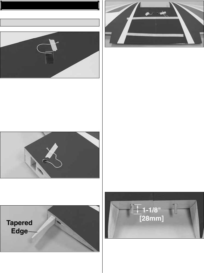
4. Locate the 1/8" x 6" x 3-1/8" [3mm x 150mm x 78mm] plywood wing bolt plate. Draw a vertical and horizontal centerline onto the plate as shown in the photo.
INSTALL THE STABILIZER
5. Draw a line 3-1/8" [78mm] to each side of the center of the wing through the center of the bolt holes.
7
Remove Covering
1. Remove the covering from the fuselage sides in the location for the horizontal stabilizer.
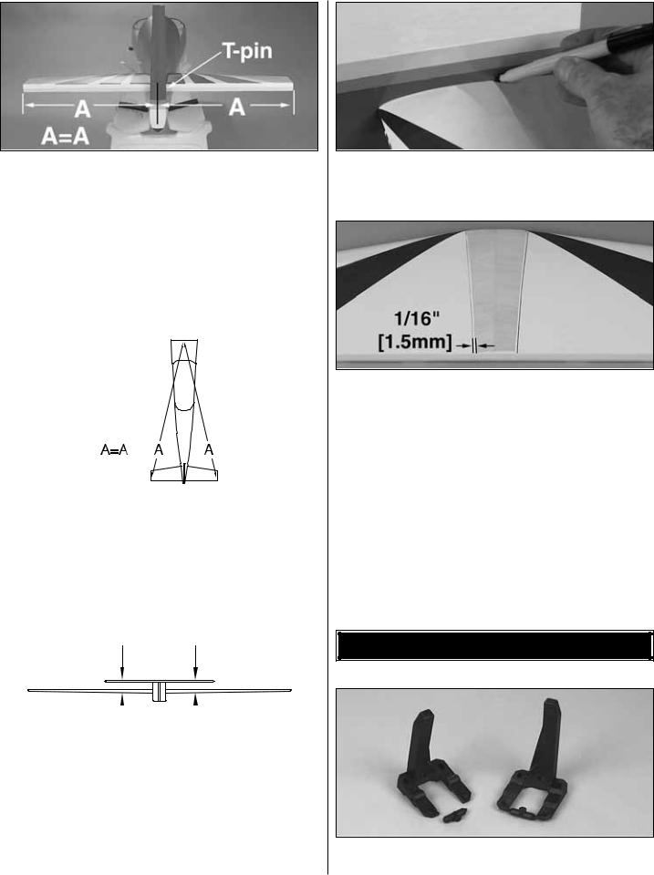
2. Slide the stabilizer into the fuselage. Center the stabilizer in the fuselage by measuring the distance from the fuselage to the tip of the stabilizer. The stabilizer is centered when the measurements from both sides are equal. Place a T-pin into the stabilizer against the fuselage on one side to allow the stabilizer to be repositioned if it accidentally moves.
3. Perform the same technique for aligning the stab as was used for aligning the wing. This time, the center on the fuselage is at the front, rather than the rear. Mark the stab so it can be returned to its aligned location.
A 
 A
A
A=A
4. Mount the wing to the fuselage using the nylon bolts. Stand back 8 to 10 feet [2.5 to 3 meters] and view the model from the front and rear. The stab tips should be equally spaced above the level of the wing. If not, lightly sand the high side of the stab saddle to correct the problem. Work slowly and check the alignment often.
5. Use a felt-tip pen to mark the sides of the fuselage on the bottom and top of the stab. Remove the stab from the fuselage.
6. Use a fresh #11 blade to carefully cut through the covering 1/16" [1.5mm] inside the lines you marked on the bottom and top of the stab that indicate the fuse sides. Do not cut the wood under the covering! This will weaken the structure and may cause the stab to fail in flight.
Remove the covering from the center of the stab within the lines you cut.
7. Use a liberal coating of 30-minute epoxy to glue the stab in position. Hold the stab in position with weights while the epoxy cures. Double check the alignment with the wing and fuse while the epoxy cures.
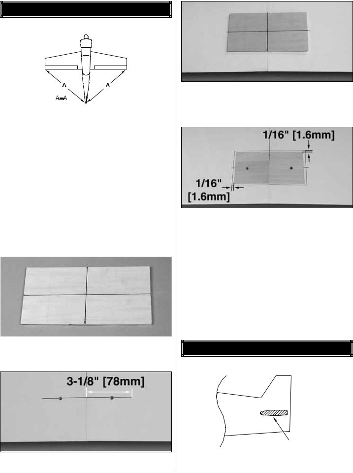
IMPORTANT: Form a thin epoxy fillet along the fuse sides where the epoxy squeezes out to create a fuelproof seal between the stab and fuselage.
ENGINE INSTALLATION
1. Cut or break the “spreader bar” from each engine mount half. Carefully trim any extra material left by the
8
spreader bar from each mount half. The surfaces where the spreader bars were attached must be smooth to allow the mount halves to fit together. Trim the flashing off any rough edges if necessary.
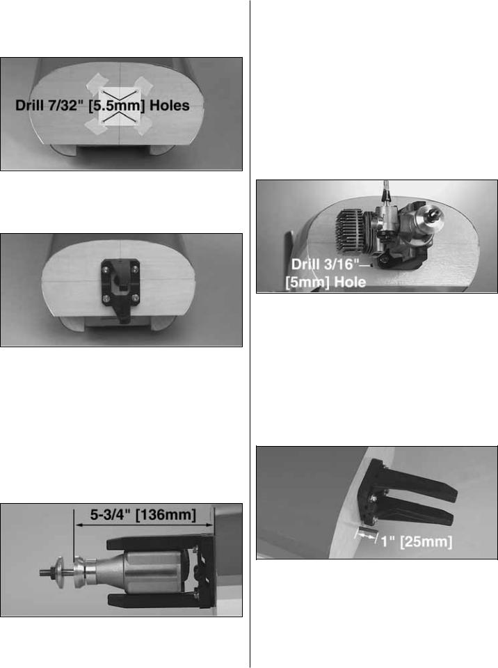
2. Copy the engine mount template from the back page and tape it to the firewall as shown. At the locations on the template, drill four 7/32" [5.5mm] holes in the firewall for the engine mount blind nuts.
3. Install four 8-32 blind nuts to the inside of the firewall. Pull the blind nuts into the back side of the firewall using 8-32 socket head cap screws with a flat washer under the head of each screw. Fit the two halves of the Engine Mount together. Use four #8 flat washers and four 8-32 x 1" socket head cap screws to secure the engine mount to the firewall. Do not tighten the screws at this time, as the mount must be adjusted for the engine.
4. Test fit your engine into the mount. Adjust the width of the rails to fit the engine snugly. Tighten the mount screws to allow marking the engine mounting holes without moving the rails.
5. Position the engine on the engine mount rails so the propeller thrust washer is 5-3/4" [136mm] ahead of the firewall. Use a Great Planes Dead Center Hole Locator (GPMR8130) (not included) or a sharpened piece of wire to
scribe the four engine mount holes onto the rails. Use a center punch at the marks to prevent the drill bit from wandering, then drill #29 pilot holes through the rails. Be sure to hold the drill perpendicular to the rails. If you have access to a drill press, this is a good tool for this purpose. Use an 8-32 tap to tap the holes for the 8-32 screws. Use four 8-32 x 1" socket head cap screws to secure the engine to the mount.
6. Drill a 3/16" [5mm] hole in the firewall for the throttle pushrod. The hole location will depend on whether you are installing a 2-stroke or 4-stroke engine.
7. Roughen the outside surface of the 36" [910mm] throttle pushrod tube with coarse grit sandpaper. Insert the pushrod tube through the hole in the firewall. Push it in until it protrudes 1" [25mm] in front of the firewall. Use medium CA to glue the tube to the firewall, but leave it free inside the fuselage until the servos are installed.
Note: The engine has been removed from the above picture for clarity.
9
 Loading...