


INSTRUCTION MANUAL
SPECIFICATIONS
Wingspan: |
38 in [965mm] |
Radio: Four channel (minimum) |
Motor: RimFire .10 (35-30-1250) |
Length: |
41.5 in [1055mm] |
Five channel computer radio |
|
Weight: 28– 32 oz [795– 905 g] |
|
||
with mixing capabilities |
|
||
Wing Area: |
375 in2 [24.2 dm2] |
(for separate ailerons) |
|
Wing Loading: |
10.8– 12.3 oz/ft2 [33– 38 g/dm2] |
|
|
WARRANTY
Great Planes® Model Manufacturing Co. guarantees this kit to be free from defects in both material and workmanship at the date of purchase. This warranty does not cover any component parts damaged by use or modification. In no case shall Great
Planes’ liability exceed the original cost of the purchased kit.
Further, Great Planes reserves the right to change or modify this warranty without notice.
In that Great Planes has no control over the final assembly or material used for final assembly, no liability shall be assumed nor accepted for any damage resulting from the use by the user of the final user-assembled product. By the act of using the user-assembled product, the user accepts all resulting liability.
If the buyer is not prepared to accept the liability associated with the use of this product, the buyer is advised to return
this kit immediately in new and unused condition to the place of purchase.
To make a warranty claim send the defective part or item to Hobby Services at the address below:
Hobby Services
3002 N. Apollo Dr. Suite 1
Champaign IL 61822 USA
Include a letter stating your name, return shipping address, as much contact information as possible (daytime telephone number, fax number, e-mail address), a detailed description of the problem and a photocopy of the purchase receipt. Upon receipt of the package the problem will be evaluated as quickly as possible.
READ THROUGH THIS MANUAL BEFORE STARTING CONSTRUCTION. IT CONTAINS IMPORTANT INSTRUCTIONS AND WARNINGS CONCERNING THE ASSEMBLY AND USE OF THIS MODEL.
Champaign, Illinois
(217) 398-8970, Ext 5 airsupport@greatplanes.com
Entire Contents © 2013 Hobbico,® Inc. All rights reserved. |
GPMA1552 Mnl |
TABLE OF CONTENTS
INTRODUCTION . . . . . . . . . . . . . . . . . . . . . . . . . . . . . . . . 2
Academy of Model Aeronautics . . . . . . . . . . . . . . . . . . 2
SAFETY PRECAUTIONS . . . . . . . . . . . . . . . . . . . . . . . . . 2
DECISIONS YOU MUST MAKE. . . . . . . . . . . . . . . . . . . . . 3
Radio Equipment . . . . . . . . . . . . . . . . . . . . . . . . . . . . . 3
Transmitter . . . . . . . . . . . . . . . . . . . . . . . . . . . . . . . . . . 3
Receiver. . . . . . . . . . . . . . . . . . . . . . . . . . . . . . . . . . . . 3
Servos . . . . . . . . . . . . . . . . . . . . . . . . . . . . . . . . . . . . . 3
Connectors. . . . . . . . . . . . . . . . . . . . . . . . . . . . . . . . . . 3
Motor Recommendations. . . . . . . . . . . . . . . . . . . . . . . 3
ESC (Electronic Speed Control) . . . . . . . . . . . . . . . . . 3
Propeller. . . . . . . . . . . . . . . . . . . . . . . . . . . . . . . . . . . . 3
Flight Battery . . . . . . . . . . . . . . . . . . . . . . . . . . . . . . . . 3
ADDITIONAL ITEMS REQUIRED . . . . . . . . . . . . . . . . . . . 4
Required Adhesives & Building Supplies . . . . . . . . . . . 4
Optional Supplies and Tools. . . . . . . . . . . . . . . . . . . . . 4
IMPORTANT BUILDING NOTES. . . . . . . . . . . . . . . . . . . . 4
KIT INSPECTION. . . . . . . . . . . . . . . . . . . . . . . . . . . . . . . . 4
ORDERING REPLACEMENT PARTS . . . . . . . . . . . . . . . . 4
KIT CONTENTS. . . . . . . . . . . . . . . . . . . . . . . . . . . . . . . . . 5
PREPARATIONS . . . . . . . . . . . . . . . . . . . . . . . . . . . . . . . . 6
ASSEMBLE THE WINGS. . . . . . . . . . . . . . . . . . . . . . . . . . 6
Install the Ailerons . . . . . . . . . . . . . . . . . . . . . . . . . . . . 6
ASSEMBLE THE FUSELAGE . . . . . . . . . . . . . . . . . . . . . . 7
Install the Main Landing Gear . . . . . . . . . . . . . . . . . . . 7
INTRODUCTION
The Factor 3D EP ARF was designed from the ground up to provide one of the best fl ying 3D airplanes available today. Whether you are just learning to fl y 3D or are already an expert, you will love this airplane.
For the latest technical updates or manual corrections to the Factor 3D EP ARF visit the Great Planes web site at www. greatplanes.com. Open the “Airplanes” link, and then select the Factor 3D EP ARF. If there is new technical information or changes to this model a “tech notice” box will appear in the upper left corner of the page.
Academy of Model Aeronautics
We urge you to join the AMA (Academy of Model Aeronautics) and a local R/C club.The AMA is the governing body of model aviation and membership is required to fl y at AMA clubs. Though joining the AMA provides many benefi ts, one of the primary reasons to join is liability protection. Coverage is not limited to flying at contests or on the club field. It even applies to fl ying at public demonstrations and air shows. Failure to comply with the Safety Code (excerpts printed in the back of the manual) may endanger insurance coverage. Additionally, training programs and instructors are available at AMA club
Install the Elevator & Rudder Servos . . . . . . . . . . . . . . 7
Install the Stab and Elevator . . . . . . . . . . . . . . . . . . . . 8
Install the Motor, Speed Control and Receiver. . . . . . 11
Install the Cowl. . . . . . . . . . . . . . . . . . . . . . . . . . . . . . 12
Install the Wheel and Wheel Pants. . . . . . . . . . . . . . . 13
Apply the Decals . . . . . . . . . . . . . . . . . . . . . . . . . . . . 14
GET THE MODEL READY TO FLY . . . . . . . . . . . . . . . . . 14
Check the Control Directions . . . . . . . . . . . . . . . . . . . 14
Set the Control Throws. . . . . . . . . . . . . . . . . . . . . . . . 14
Finish the Model. . . . . . . . . . . . . . . . . . . . . . . . . . . . . 15
Balance the Model (C.G.). . . . . . . . . . . . . . . . . . . . . . 15
Balance the Model Laterally. . . . . . . . . . . . . . . . . . . . 16
PREFLIGHT . . . . . . . . . . . . . . . . . . . . . . . . . . . . . . . . . . . 16
Identify Your Model. . . . . . . . . . . . . . . . . . . . . . . . . . . 16
Charge the Batteries . . . . . . . . . . . . . . . . . . . . . . . . . 16
Range Check . . . . . . . . . . . . . . . . . . . . . . . . . . . . . . . 16
MOTOR SAFETY PRECAUTIONS . . . . . . . . . . . . . . . . . 16
AMA SAFETY CODE EXCERPTS . . . . . . . . . . . . . . . . . 16
General . . . . . . . . . . . . . . . . . . . . . . . . . . . . . . . . . . . 16
Radio Control . . . . . . . . . . . . . . . . . . . . . . . . . . . . . . . 17
CHECK LIST . . . . . . . . . . . . . . . . . . . . . . . . . . . . . . . . . . 17
FLYING. . . . . . . . . . . . . . . . . . . . . . . . . . . . . . . . . . . . . . . 17
Takeoff . . . . . . . . . . . . . . . . . . . . . . . . . . . . . . . . . . . . 18
Flight . . . . . . . . . . . . . . . . . . . . . . . . . . . . . . . . . . . . . 18
Landing . . . . . . . . . . . . . . . . . . . . . . . . . . . . . . . . . . . 18
sites to help you get started the right way.There are over 2,500 AMA chartered clubs across the country. Contact the AMA at the address or toll-free phone number below:
Academy of Model Aeronautics
5151 East Memorial Drive
Muncie, IN 47302-9252
Tele. (800) 435-9262
Fax (765) 741-0057
Or via the Internet at: http://www.modelaircraft.org
IMPORTANT!!! Two of the most important things you can do to preserve the radio controlled aircraft hobby are to avoid fl ying near full-scale aircraft and avoid fl ying near or over groups of people.
SAFETY PRECAUTIONS
PROTECT YOUR MODEL, YOURSELF & OTHERS...
FOLLOW THESE IMPORTANT SAFETY PRECAUTIONS
1. Your Factor 3D EP ARF should not be considered a toy, but rather a sophisticated, working model that functions very much like a full-size airplane. Because of its performance capabilities, the Factor 3D, if not assembled and operated
2

correctly, could possibly cause injury to yourself or spectators and damage to property.
2.You must assemble the model according to the instructions. Do not alter or modify the model, as doing so may result in an unsafe or unflyable model. In a few cases the instructions may differ slightly from the photos. In those instances the written instructions should be considered as correct.
3.You must take time to build straight, true and strong.
4.You must use an R/C radio system that is in fi rst-class condition, and a correctly sized engine and components (fuel tank, wheels, etc.) throughout the building process.
5.You must correctly install all R/C and other components so that the model operates correctly on the ground and in the air.
6.You must check the operation of the model before every
flight to insure that all equipment is operating and that the model has remained structurally sound. Be sure to check clevises or other connectors often and replace them if they show any signs of wear or fatigue.
7. If you are not an experienced pilot or have not flown this type of model before, we recommend that you get the assistance of an experienced pilot in your R/C club for your fi rst fl ights. If you’re not a member of a club, your local hobby shop has information about clubs in your area whose membership includes experienced pilots.
We, as the kit manufacturer, provide you with a top quality, thoroughly tested kit and instructions, but ultimately the quality and flyability of your finished model depends on how you build it; therefore, we cannot in any way guarantee the performance of your completed model, and no representations are expressed or implied as to the performance or safety of your completed model.
REMEMBER: Take your time and follow the instructions to end up with a well-built model that is straight and true.
DECISIONS YOU MUST MAKE
This is a partial list of items required to fi nish the Factor 3D EP ARF that may require planning or decision making before starting to build.
Radio Equipment
A 4-channel radio system with four micro servos and receiver are required for this plane.
The servos and receiver shown in the manual are Futaba® S3156 Servos (FUTM0656) and the Futaba 617FS FASST™ 2.4GHz receiver (FUTL7627)
Transmitter
4-channel radio (minimum)
Receiver
617FS FASST 2.4GHz receiver [FUTL7627]
Servos
(4) Futaba® S3156 Servos [FUTM0656] [ 28 oz-in (2.0 kg-cm) @ 4.8 V of torque]
Connectors
(1) “Y” harness [FUTM4130]
(2) 16" extensions [FUTM3955]
Motor Recommendations
The Factor EP ARF comes with a mounting box for the Great Planes RimFire brushless out-runner motor. The motor has been tested with this plane and works well.
Great Planes RimFire .10 (35-30-1250) Brushless Outrunner Motor [GPMG4595]
ESC (Electronic Speed Control)
A brushless ESC (electronic speed control) is required for the recommended motor set-up. We recommend using the:
Great Planes Silver Series SS-35A Brushless ESC [GPMM1830]
Propeller
For our testing we used the:
Great Planes 10 4.5 SF propeller. (GPMQ6660)
APC 10 4.7 SF propeller. (APCQ5015)
Flight Battery
We recommend:
Great Planes Power Series™ LiPo 2200 mAh, 11.1V, 30C battery (GPMP0861)
or
Flight Power® 2200 mAh 11.1V (FPWP6198)
3
ADDITIONAL ITEMS REQUIRED
Required Adhesives & Building Supplies
This is the list of adhesives and building supplies required to fi nish the Factor 3D EP ARF. Order numbers are provided in parentheses.
1/2 oz. [15 g] Thin Pro CA (GPMR6001)
1/2 oz. [15 g] Medium Pro CA+ (GPMR6007)
Drill bits: 1/16" [1.6 mm], 5/64" [ 2 mm]
#1 Hobby knife (HCAR0105)
#11 blades (5-pack, HCAR0211)
Small T-pins (100, HCAR5100)
Optional Supplies and Tools
Here is a list of optional tools mentioned in the manual that will help you build the Factor 3D EP ARF 580 EP.
Pro 30-minute epoxy (GPMR6047)
Denatured alcohol (for epoxy clean up)
2 oz. [ 57g] spray CA activator (GPMR6035)
CA applicator tips (HCAR3780)
CA debonder (GPMR6039)
Epoxy brushes (6, GPMR8060)
Mixing sticks (50, GPMR8055)
Mixing cups (GPMR8056)
Threadlocker thread locking cement (GPMR6060)
AccuThrow™ Defl ection Gauge (GPMR2405)
CG Machine™ (GPMR2400)
21st Century® sealing iron [COCR2700]
21st Century iron cover [COVR2702]
IMPORTANT BUILDING NOTES
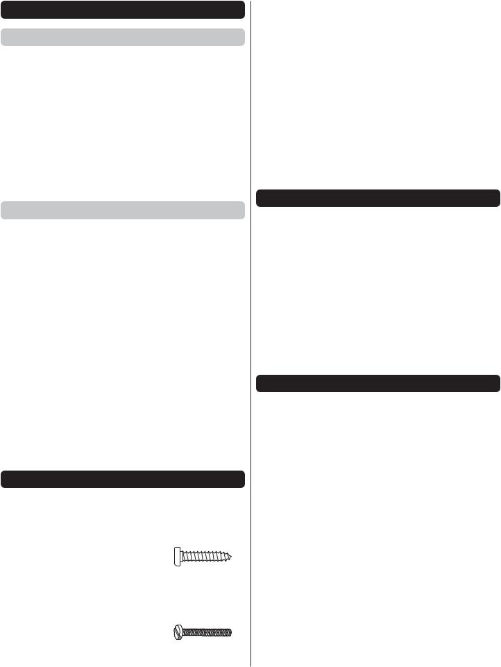
There are two types of screws used in this kit:
Sheet Metal Screws are designated by a number and a length. For example #6 3/4" [19mm].
This is a number six screw that is 3/4" [19 mm] long.
Machine Screws are designated by a number, threads per inch, and a length. For example 4-40 3/4" [19mm].
This is a number four screw that is 3/4" [19 mm] long with forty threads per inch.
When you see the term test fit in the instructions, it means that you should fi rst position the part on the assembly without using any glue, then slightly modify or custom fit the part as necessary for the best fi t.
Whenever the term glue is written you should rely upon your experience to decide what type of glue to use. When a specifi c type of adhesive works best for that step, the instructions will make a recommendation.
We recommend 30-minute epoxy only, because you will need the working time or the additional strength
Photos and sketches are placed before the step they refer to. Frequently you can study photos in following steps to get another view of the same parts.
KIT INSPECTION
Before starting to build, take an inventory of this kit to make sure it is complete, and inspect the parts to make sure they are of acceptable quality. If any parts are missing or are not of acceptable quality, or if you need assistance with assembly, contact Product Support.When reporting defective or missing parts, use the part names exactly as they are written in the Kit Contents list.
Great Planes Product Support |
|
3002 N Apollo Drive, Suite 1 |
Ph: (217) 398-8970, ext. 5 |
Champaign, IL 61822 |
Fax: (217) 398-7721 |
E-mail: airsupport@greatplanes.com
ORDERING REPLACEMENT PARTS
Replacement parts for the Great Planes Factor 3D EP ARF are available using the order numbers in the Replacement Parts List that follows. The fastest, most economical service can be provided by your hobby dealer or mail-order company.
To locate a hobby dealer, visit the Hobbico web site at www. hobbico.com. Choose “Where to Buy” at the bottom of the menu on the left side of the page. Follow the instructions provided on the page to locate a U.S., Canadian or International dealer. If a hobby shop is not available, replacement parts may also be ordered from Tower Hobbies at www.towerhobbies.com, or by calling toll free (800) 637-6050.
Parts may also be ordered directly from Hobby Services by calling (217) 398-0007, or via facsimile at (217) 398-7721, but full retail prices and shipping and handling charges will apply. Illinois and Nevada residents will also be charged sales tax. If ordering via fax, include a Visa or MasterCard number and expiration date for payment.
Mail parts orders |
Hobby Services |
and payments by |
3002 N Apollo Drive, Suite 1 |
personal check to: |
Champaign IL 61822 |
4
Be certain to specify the order number exactly as listed in the Replacement Parts List. Payment by credit card or personal check only; no C.O.D.
If additional assistance is required for any reason contact Product Support by e-mail at productsupport@greatplanes. com, or by telephone at (217) 398-8970.
|
REPLACEMENT PARTS LIST |
|
|
Order No. |
Description |
GPMA2100 |
Fuselage |
|
|
GPMA2101 |
Wing Set |
GPMA2102 |
Tail Surface Set |
|
|
GPMA2103 |
Canopy Hatch |
GPMA2104 |
Cowl |
GPMA2105 |
Landing Gear |
GPMA2106 |
Wheel Pants |
|
|
GPMA2107 |
Spinner |
GPMA2108 |
Tail Wheel Wire |
GPMA2109 |
Wing Bolts |
GPMA2110 |
Wing Tube |
|
|
GPMA2111 |
Decal Sheet |
|
|
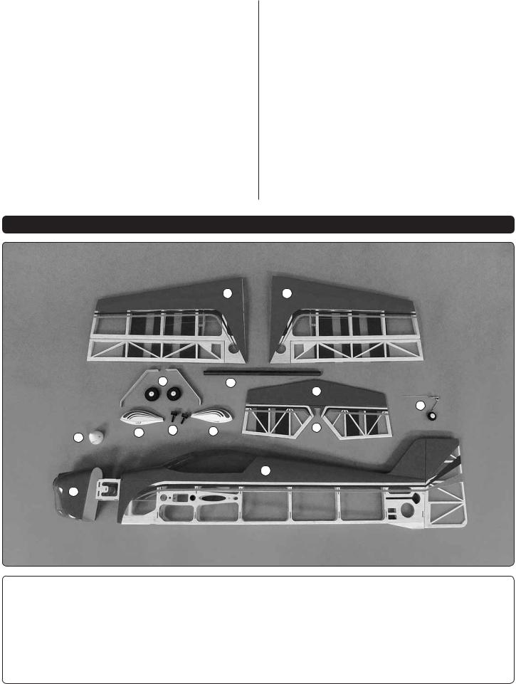
KIT CONTENTS
11 |
12 |
|
5 |
|
10 |
|
|
|
8 |
|
|
|
9 |
4 |
6 |
4 |
7 |
|
|||
3 |
|
|
|
|
|
|
1 |
2
Kit Contents |
|
|
|
|
1. |
Fuselage |
5. |
Wheels |
9. Tail Wheel Set |
2. |
Cowl |
6. |
Wing Bolts |
10. Wing Tube |
3. |
Spinner |
7. |
Elevator |
11. Left Wing |
4. |
Wheel Pants |
8. |
Stabilizer |
12. Right Wing |
5

PREPARATIONS
1. If you have not done so already, remove the major parts of the kit from the box and inspect for damage. If any parts are damaged or missing, contact Product Support at the address or telephone number listed in the “Kit Inspection” section on page 4.
2. Remove the tape and separate the elevators from the stab. Use a covering iron with a covering sock on medium heat to tighten the covering on the wings, fuselage, etc. if necessary. Apply pressure over sheeted areas to thoroughly bond the covering to the wood. Caution: The Factor 3D EP ARF was designed to be strong where needed, but light weight for excellent fl ight performance. Care must be taken when assembling the plane to avoid damage.
ASSEMBLE THE WINGS
Install the Ailerons
Do the right wing first so your work matches the photos the first time through.
Install the Aileron Servos and Pushrods
1. Inside the servo bay a string is taped. Carefully remove the tape and string from the servo bay. Tie the string to the servo lead. Pull the string and the servo lead through the wing. Untie the string from the lead.
2. Install the servo into the servo opening. Drill a 1/16" [1.6 mm] hole though the servo mount, into the wood in the
wing. Install and then remove a servo mounting screw into each of the holes you have drilled. Apply a drop of thin CA into the holes to harden the threads. Once the glue has cured install the servo into the servo opening. Center the servo and then install a servo arm as shown.The arm should be pointing towards the wing root.
3. Drill a 5/64" [2 mm] hole through the hole in the servo arm as shown.
4. Thread a nylon clevis, 20 turns, onto a 6" [152 mm] wire pushrod.
Hinge Line |
Hinge Line |
Correct |
Incorrect |
Refer to this picture for steps 5-7.
5. Cut the mounting plate from the control horn. Attach the clevis in the outer hole of a nylon control horn. Place the control horn in line with hole you drilled in the servo arm. When positioned properly the control horn will rest on a hardwood plate in the aileron. Mark the location of the mounting holes onto the aileron. Drill a 1/16" [1.6 mm] hole on the marks, drilling through the plywood plate but not through the top of the aileron.
6
 Loading...