


™
MX 30cc
|
|
|
|
|
|
|
INSTRUCTION |
|||
|
|
|
|
|
|
|
|
MANUAL |
||
SPECIFICATIONS |
|
|
|
|
|
|
|
|
|
|
Wingspan: |
80 in [2030 mm] |
|
Weight: |
|
12.75 |
13.75 lbs |
|
Radio: |
4-6 Channel |
|
|
|
|||||||||
|
|
|
|
[5780 |
6230 g] |
|
|
|
|
|
Length: |
67 in [1700 mm] |
|
|
Engine: |
1.8− 2.0 cu in [30 − 35 cc] |
|||||
|
|
|
|
|
|
|||||
|
Wing |
|
25– 27 oz/ft2 |
|
||||||
|
|
|
|
|
|
|
|
|||
|
|
|
|
|
|
|
||||
Wing Area: |
|
|
|
Electric: |
|
|
||||
1184 in2 [76.4 dm2] |
|
Loading: |
|
[76– 82 g/dm2] |
|
RimFire 1.60 (63-62-250) Brushless |
||||
WARRANTY
Great Planes® Model Manufacturing Co. guarantees this kit to be free from defects in both material and workmanship at the date of purchase. This warranty does not cover any component parts damaged by use or modification. In no case shall Great
Planes’ liability exceed the original cost of the purchased kit.
Further, Great Planes reserves the right to change or modify this warranty without notice.
In that Great Planes has no control over the final assembly or material used for final assembly, no liability shall be assumed nor accepted for any damage resulting from the use by the user of the final user-assembled product. By the act of using the user-assembled product, the user accepts all resulting liability.
If the buyer is not prepared to accept the liability associated with the use of this product, the buyer is advised to return
this kit immediately in new and unused condition to the place of purchase.
To make a warranty claim send the defective part or item to Hobby Services at the address below:
Hobby Services
3002 N. Apollo Dr. Suite 1
Champaign IL 61822 USA
Include a letter stating your name, return shipping address, as much contact information as possible (daytime telephone number, fax number, e-mail address), a detailed description of the problem and a photocopy of the purchase receipt. Upon receipt of the package the problem will be evaluated as quickly as possible.
READ THROUGH THIS MANUAL BEFORE STARTING CONSTRUCTION. IT CONTAINS IMPORTANT INSTRUCTIONS AND WARNINGS CONCERNING THE ASSEMBLY AND USE OF THIS MODEL.
Champaign, Illinois
(217) 398-8970, Ext 5 airsupport@greatplanes.com
© 2015 Great Planes Model Mfg. A subsidiary of Hobbico,® Inc. |
GPMA1210 |
TABLE OF CONTENTS
INTRODUCTION . . . . . . . . . . . . . . . . . . . . . . . . . . . . . . . .2
SAFETY PRECAUTIONS . . . . . . . . . . . . . . . . . . . . . . . . .2
DECISIONS YOU MUST MAKE . . . . . . . . . . . . . . . . . . . .3
EngineRecommendations . . . . . . . . . . . . . . . . . . . . . .3
Motor Recommendations. . . . . . . . . . . . . . . . . . . . . . .3
Radio Equipment . . . . . . . . . . . . . . . . . . . . . . . . . . . . .3
ADDITIONAL ITEMS REQUIRED. . . . . . . . . . . . . . . . . . .4
Required Hardware and Accessories . . . . . . . . . . . . .4
Adhesives and Building Supplies. . . . . . . . . . . . . . . . .4
Optional Supplies and Tools . . . . . . . . . . . . . . . . . . . .4
IMPORTANT BUILDING NOTES . . . . . . . . . . . . . . . . . . .4
MODEL INSPECTION . . . . . . . . . . . . . . . . . . . . . . . . . . . .4
CONTENTS . . . . . . . . . . . . . . . . . . . . . . . . . . . . . . . . . . . .5
ORDERING REPLACEMENT PARTS . . . . . . . . . . . . . . .5
PREPARATIONS . . . . . . . . . . . . . . . . . . . . . . . . . . . . . . . .6
ASSEMBLE THE WINGS . . . . . . . . . . . . . . . . . . . . . . . . .6
Aileron Servo Installation . . . . . . . . . . . . . . . . . . . . . . . .
Flap Servo Installation (Optional) . . . . . . . . . . . . . . . . .
ASSEMBLE THE FUSELAGE . . . . . . . . . . . . . . . . . . . . 14
Install the Tail . . . . . . . . . . . . . . . . . . . . . . . . . . . . . . . . .
Install the Main Landing Gear . . . . . . . . . . . . . . . . . . . .
Install the Rudder and Elevator Servos . . . . . . . . . . . . .
Motor Installation . . . . . . . . . . . . . . . . . . . . . . . . . . . . . .
Engine Installation . . . . . . . . . . . . . . . . . . . . . . . . . . . . .
Assemble the Fuel Tank . . . . . . . . . . . . . . . . . . . . . . . .
Install the Fuel Tank. . . . . . . . . . . . . . . . . . . . . . . . . . . .
Install the Cowl. . . . . . . . . . . . . . . . . . . . . . . . . . . . . . . .
Apply the Decals . . . . . . . . . . . . . . . . . . . . . . . . . . . . . .
GET THE MODEL READY TO FLY. . . . . . . . . . . . . . . . .32
Check the Control Directions. . . . . . . . . . . . . . . . . . .32
Set the Control Throws . . . . . . . . . . . . . . . . . . . . . . .32
Install the Propeller . . . . . . . . . . . . . . . . . . . . . . . . . . . .
Balance the Model Laterally . . . . . . . . . . . . . . . . . . .35
Balance the Model (C.G.) . . . . . . . . . . . . . . . . . . . . .35
PREFLIGHT. . . . . . . . . . . . . . . . . . . . . . . . . . . . . . . . . . .35
Identify Your Model . . . . . . . . . . . . . . . . . . . . . . . . . .35
Charge the Batteries . . . . . . . . . . . . . . . . . . . . . . . . .36
Ground Check and Range Check . . . . . . . . . . . . . . .36
ENGINE SAFETY PRECAUTIONS. . . . . . . . . . . . . . . . .36
AMA SAFETY CODE (excerpts) . . . . . . . . . . . . . . . . . .36
General . . . . . . . . . . . . . . . . . . . . . . . . . . . . . . . . . . .37
Radio Control. . . . . . . . . . . . . . . . . . . . . . . . . . . . . . .37
CHECK LIST . . . . . . . . . . . . . . . . . . . . . . . . . . . . . . . . . .37
FLYING. . . . . . . . . . . . . . . . . . . . . . . . . . . . . . . . . . . . . . .38
Fuel Mixture Adjustments . . . . . . . . . . . . . . . . . . . . .38
Takeoff . . . . . . . . . . . . . . . . . . . . . . . . . . . . . . . . . . . .38
Flight . . . . . . . . . . . . . . . . . . . . . . . . . . . . . . . . . . . . .38
Landing . . . . . . . . . . . . . . . . . . . . . . . . . . . . . . . . . . .38
INTRODUCTION
Continuing with the success of the Escapade line, Great Planes brings you the Escapade MX 30cc ARF. This is a great first gas powered model. The plane is as easy to fl y as a .60 size sport plane. The optional fl aps allow you to add the fl aps later if you desire. We believe you will be very pleased with the ease of assembly and fl ight performance of the Escapade MX 30cc ARF.
For the latest technical updates or manual corrections to the Escapade MX 30cc ARF visit the Great Planes web site at www.greatplanes.com. Open the “Airplanes” link, then select the Escapade MX 30cc ARF. If there is new technical information or changes to this model a “tech notice” box will appear in the upper left corner of the page.
Academy of Model Aeronautics: If you are not already a member of the AMA, please join! The AMA is the governing body of model aviation and membership provides liability insurance coverage, protects modelers’ rights and interests and is required to fl y at most R/C sites.
Academy of Model Aeronautics
5151 East Memorial Drive
Muncie, IN 47302-9252
Tele. (800) 435-9262
Fax (765) 741-0057
Or via the Internet at: http://www.modelaircraft.org
IMPORTANT!!! Two of the most important things you can do to preserve the radio controlled aircraft hobby are to avoid fl ying near full-scale aircraft and avoid fl ying near or over groups of people.
SAFETY PRECAUTIONS
Protect Your Model,Yourself & Others…
Follow These Important Safety Precautions
1.Your Escapade MX 30cc ARF should not be considered a toy, but rather a sophisticated, working model that functions very much like a full-size airplane. Because of its performance capabilities, the Escapade MX 30cc ARF, if not assembled and operated correctly, could possibly cause injury to yourself or spectators and damage to property.
2.You must assemble the model according to the instructions. Do not alter or modify the model, as doing so may result in an unsafe or unfl yable model. In a few cases the instructions may differ slightly from the photos. In those instances the written instructions should be considered as correct.
3.You must take time to build straight, true and strong.
4.You must use an R/C radio system that is in good condition, a correctly sized engine, and other components as specifi ed in this instruction manual. All components must be correctly installed so that the model operates correctly on the ground and in the air. You must check the operation of the model and all components before every fl ight.
5.If you are not an experienced pilot or have not fl own this type of model before, we recommend that you get the assistance of an experienced pilot in your R/C club for your fi rst fl ights. If you’re not a member of a club, your local hobby shop has information about clubs in your area whose membership includes experienced pilots.
2
6.While this kit has been fl ight-tested to exceed normal use, if an engine larger than one in the recommended range is used, the modeler is responsible for taking steps to reinforce the high stress points and/or substituting hardware more suitable for the increased stress.
7.WARNING: The cowl and wheel pants included in this kit are made of fi berglass, the fi bers of which may cause eye, skin and respiratory tract irritation. Never blow into a part to remove fi berglass dust, as the dust will blow back into your eyes. Always wear safety goggles, a particle mask and rubber gloves when grinding, drilling and sanding fi berglass parts. Vacuum the parts and the work area thoroughly after working with fi berglass parts.
8.If you are building this plane as electric powered, set the failsafe on your transmitter and follow the safety precautions in the back of the manual.
We, as the kit manufacturer, provide you with a top quality, thoroughly tested kit and instructions, but ultimately the quality and flyability of your finished model depends on how you build it; therefore, we cannot in any way guarantee the performance of your completed model, and no representations are expressed or implied as to the performance or safety of your completed model.
REMEMBER: Take your time and follow the instructions to end up with a well-built model that is straight and true.
DECISIONS YOU MUST MAKE
This is a partial list of items required to finish the Escapade MX 30cc ARF that may require planning or decision making before starting to build. Order numbers are provided in parentheses.
Engine Recommendations
The recommended engine size range for the Escapade MX 30cc ARF is a 30 – 35cc [1.8 – 2.0 ci.] two-stroke gasoline engine. We used the DLE 30 engine for our model. Other engines can also be used but you may need to make modifi cations for mounting those engines.
Motor Recommendations
Great Planes RimFire 1.60 [63-62-250] Outrunner Brushless Motor (GPMG4795)
Great Planes SS-80 ESC (GPMM1860)
Great Planes 6mm Male/4mm Female Bullet Adapter (GPMM3119)
Two 5S FlightPower LiPo Pro50 or FP50 5000mAh 18.5V Batteries (FPWP5102 or FPWP5505)
Spinner Adapter Kit (GPMQ4589)
Radio Equipment
The Escapade MX 30cc ARF can be flown with a minimum of a 4-channel radio. For our installation we used six channels. One channel each for the throttle, choke, elevator, rudder ailerons and flaps.
RECOMMENDED SERVOS: All control surfaces require the use of a high-quality servo of at least 85 oz-in of torque. A servo of 40 oz-in of torque can be used for the throttle and choke.
|
|
MINIMUM |
SUGGESTED |
|
FUNCTION |
# |
TORQUE |
SERVO |
|
|
|
|
|
|
ELEVATORS |
2 |
85 oz-in |
Futaba S3305 |
|
FUTM0045 |
||||
|
|
|
||
RUDDER |
1 |
85 oz-in |
Futaba S3305 |
|
FUTM0045 |
||||
|
|
|
||
AILERONS |
2 |
85 oz-in |
Futaba S3305 |
|
FUTM0045 |
||||
|
|
|
||
OPTIONAL |
2 |
85 oz-in |
Futaba S3305 |
|
FLAPS |
FUTM0045 |
|||
|
|
|||
THROTTLE |
1 |
54 oz-in |
Futaba S9001 |
|
FUTM0075 |
||||
|
|
|
||
|
|
|
|
|
OPTIONAL |
1 |
54 oz-in |
Futaba S9001 |
|
CHOKE |
FUTM0075 |
|||
|
|
|||
TOTAL |
9 Servos |
|
||
|
|
|
|
|
ELECTRIC MOTOR INSTALLATION
(2) 20" Servo extension (FUTM4147) OR
(2)24" Servo extension (TACM2721)
(3) 8" Servo extension (FUTM4140) OR
(2)6" Servo extension (TACM2701)
(2) Y-harness (FUTM4135) (TACM2751)
(1) Additional Y-harness for fl aps
(1) Heavy duty on/off switch (FUTM4385) (TACM2761)
(1) 1900mAh LiFe receiver battery (HCAM6521)
ADDITIONAL ITEMS FOR GAS INSTALLATION
(1) Additional Y-harness for choke if using a 6-channel receiver
(1) Heavy duty on/off switch (FUTM4385 or TACM2761)
(1) 1300mAh LiFe ignition battery (HCAM6411)
The instructions show the two aileron servos connected with a Y-harness that is plugged into the aileron channel of the receiver. If using a computer radio, the two aileron servos can be plugged into separate channels of the receiver and mixed together. The two fl ap servos and the two elevator servos also use a Y-harness. If plugging the servos into separate channels, follow the instructions included with your radio system on how to mix the channels.
3

ADDITIONAL ITEMS REQUIRED
Required Hardware and Accessories
(1) Dubro #554 X-Large Tygon Fuel Line (DUBQ0427)
(1) R/C Foam Rubber (1/4" [6mm], HCAQ1000; or 1/2" [13mm], HCAQ1050)
Propeller and spare propellers suitable for your engine.
Adhesives and Building Supplies
This is the list of Adhesives and Building Supplies that are required to fi nish the Escapade MX 30cc ARF.
1/2 oz. [15g] Thin Pro CA (GPMR6001)
Pro 30-minute epoxy (GPMR6047)
Pro 6-minute epoxy (GPMR6045)
Threadlocker thread locking cement (GPMR6060)
Mixing sticks (50, GPMR8055)
Mixing cups (GPMR8056)
Epoxy brushes (6, GPMR8060)
Denatured alcohol (for epoxy clean up)
Masking tape
Sandpaper
Drill
Drill bits: 1/16" [1.6mm], 5/64" [2mm], 3/32" [2.4mm], 1/8" [3.2mm], 3/16" [4.8mm], 13/64" [5.2mm], 1/4" [6.4mm], 25/64" [10mm]
Small metal fi le
Stick-on segmented lead weights (GPMQ4485)
Silver solder w/fl ux (STAR2000)
Hobbico 60 Watt Soldering Iron (HCAR0776)
#1 Hobby knife (RMXR6903)
#11 blades (5-pack, RMXR6930)
Rotary tool such as Dremel®
Rotary tool reinforced cut-off wheel (GPMR8200)
DLE-30 Propeller Drill Guide (DLEQ0301)
Covering Tools
Top Flite® MonoKote® Sealing Iron (TOPR2100)
Top Flite Hot Sock Iron Cover (TOPR2175)
Top Flite MonoKote Trim Seal Iron (TOPR2200)
Top Flite MonoKote Heat Gun (TOPR2000)
Coverite® 21st Century® Sealing Iron (COVR2700)
Coverite 21st Century Cover Sock (COVR2702)
Coverite 21st Century Trim Sealing Iron (COVR2750)
Optional Supplies and Tools
Here is a list of optional tools mentioned in the manual that will help you build the Escapade MX 30cc ARF.
2 oz. [57g] spray CA activator (GPMR6035)
CA applicator tips (HCAR3780)
CA debonder (GPMR6039)
36" metal ruler
Pliers with wire cutter (HCAR0625)
Robart® Super Stand II™ (ROBP1402)
Servo horn drill (HCAR0698)
AccuThrow™ Defl ection Gauge (GPMR2405)
CG Machine™ (GPMR2400)
Precision Magnetic Prop Balancer (TOPQ5700)
IMPORTANT BUILDING NOTES
Anytime a sheet metal screw is installed in wood, fi rst install the screw, remove the screw and apply a couple of drops of thin CA in the hole to harden the threads. After the CA has cured, reinstall the screw.
Anytime a threaded screw or nut is installed, a drop of threadlocker must be applied to the threads. An exception, do not use threadlocker on the screws installed in the nylon control horns.
Denatured alcohol is great for cleaning epoxy from surfaces before the epoxy cures
Replacement MonoKote colors
Jet White (TOPQ0204) |
Dove Gray (TOPQ0211) |
Black (TOPQ0208) |
True Red (TOPQ0227) |
KIT INSPECTION
Before starting to build, inspect the parts to make sure they are of acceptable quality. If any parts are missing or are not of acceptable quality, or if you need assistance with assembly, contact Product Support. When reporting defective or missing parts, use the part names exactly as they are written in the Kit Contents list.
Great Planes Product Support |
|
3002 N Apollo Drive, Suite 1 |
Ph: (217) 398-8970, ext. 5 |
Champaign, IL 61822 |
Fax: (217) 398-7721 |
E-mail: airsupport@greatplanes.com
ORDERING REPLACEMENT PARTS
Replacement parts for the Great Planes Escapade MX 30cc ARF are available using the order numbers in the Replacement Parts List that follows. The fastest, most economical service can be provided by your hobby dealer or mail-order company. Not all parts are available separately (an aileron cannot be purchased separately, but is only available with the wing kit). Replacement parts are not available from Product Support,
4
but can be purchased from hobby shops or mail order/Internet order fi rms. Hardware items (screws, nuts, bolts) are also available from these outlets.
To locate a hobby dealer, visit the Great Planes web site at www.greatplanes.com. Choose “Where to Buy”. Follow the instructions provided on the page to locate a U.S., Canadian or International dealer.
Parts may also be ordered directly from Hobby Services by calling (217) 398-0007, or via facsimile at (217) 398-7721, but full retail prices and shipping and handling charges will apply. Illinois and Nevada residents will also be charged sales tax. If ordering via fax, include a Visa® or MasterCard® number and expiration date for payment.
Mail parts orders |
Hobby Services |
and payments by |
3002 N Apollo Drive, Suite 1 |
personal check to: |
Champaign IL 61822 |
Be certain to specify the order number exactly as listed in the Replacement Parts List. Payment by credit card or personal check only; no C.O.D.
If additional assistance is required for any reason contact
Product Support by e-mail at productsupport@greatplanes. com, or by telephone at (217) 398-8970.
REPLACEMENT PARTS LIST
Order No. Description
GPMA5380 Wing Set
GPMA5381 Fuselage Set
GPMA5382 Tail Surface Set
GPMA5383 Cowl
GPMA5384 Landing Gear
GPMA5385 Wheel Pants
GPMA5386 Wing Tube
GPMA5387 Canopy/Hatch
GPMA5388 EP Motor Mount Box
GPMA5389 Spinner
GPMA5390 Tailwheel Assembly
GPMA5391 Hatch Screws
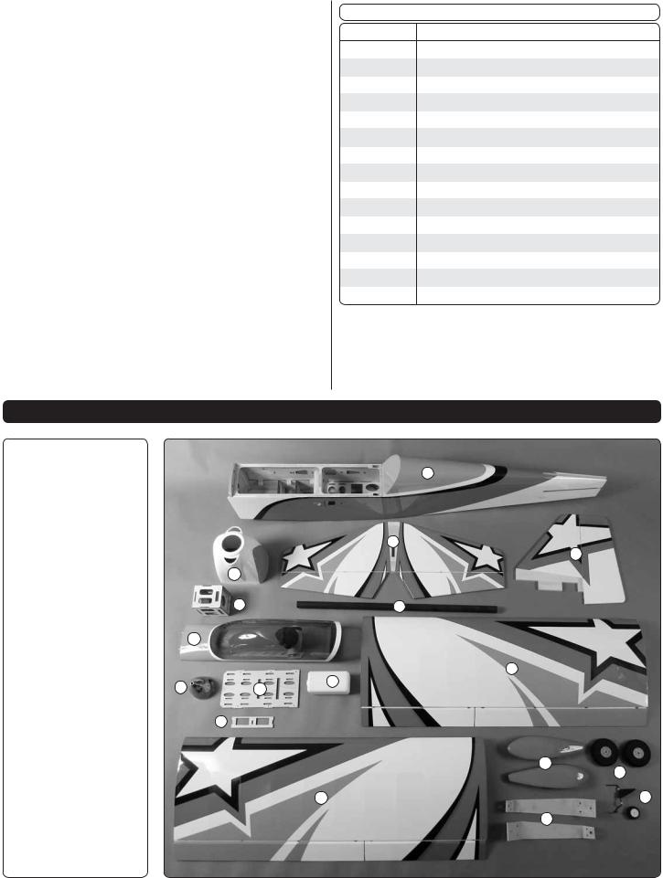
KIT CONTENTS
1.Fuselage
2.Cowl
3.Horizontal Stabilizer
4.Vertical Stabilizer
5.EP Motor Mount Box
6.Wing Tube
7.Canopy/Hatch
8.Spinner
9.Battery/Fuel Tank Tray 10. Servo Tray
11.Fuel Tank
12.Wing Halves
13.Wheel Pants
14.Main Wheels
15.Main Landing Gear
16.Tailwheel Assembly
1
|
|
3 |
|
|
4 |
|
2 |
|
|
5 |
6 |
|
7 |
|
|
|
12 |
8 |
9 |
11 |
|
||
|
10 |
|
|
|
13 |
|
|
14 |
|
12 |
16 |
|
|
15 |
5
PREPARATIONS
1. Firmly pull on each of the control surfaces to confi rm they are securely glued.
2. Tighten the covering with a covering iron as needed.
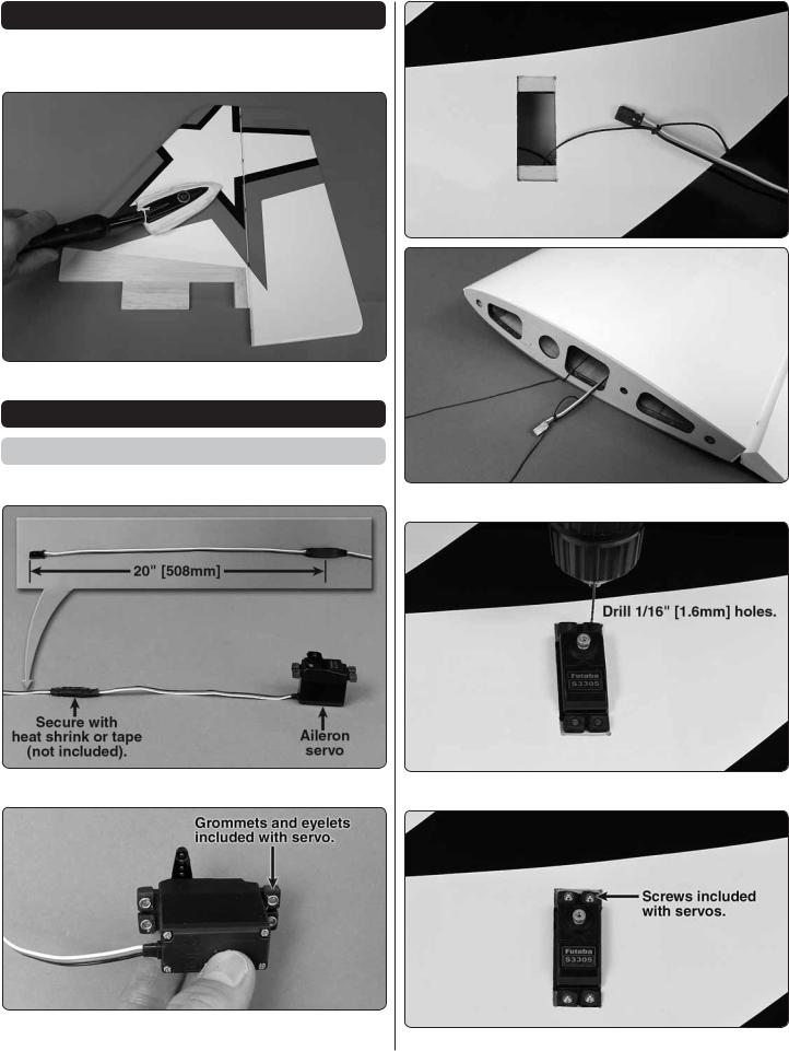
ASSEMBLE THE WING
Aileron Servo Installation
Begin with the left wing panel.
1. Install a servo lead extension (not included).
2. Install grommets and eyelets on all servos.
3. Route servo lead through wing.
4. Drill servo screw mounting hole.
5. Install servo screws.
6

6. Install servo horn.
7. Aileron pushrod components.
8. Install the 4-40 threaded clevis.
9. Attach clevis to control horn.
10. Position control horn on aileron.
11. Mount control horn.
7
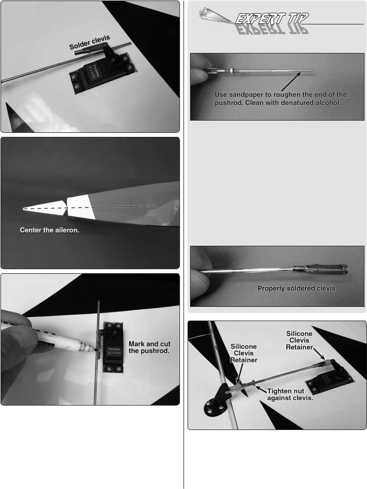
HOW TO SOLDER
Apply a few drops of soldering flux to the end of the pushrod. “Tin” the end of the pushrod by applying heat. Apply silver solder to the heated area. The pushrod should melt the solder, not the fl ame of the torch. The end of the pushrod should be tinned all the way around.
Position the solder clevis on the pushrod and apply a drop of fl ux to the joint. Apply heat and add solder. Again, the heat of the part should melt the solder, not the fl ame of the torch. Allow the part to cool naturally. Make sure the joint is thoroughly soldered. It should be shiny, not rough. Reheat if necessary.
Wipe off the fl ux residue with denatured alcohol. Coat the joint with oil to prevent rust.
12. Install the solder clevis.
13. Reinstall the aileron pushrods and slide the retainers over the clevises.
14. Repeat steps 1 – 13 to install the aileron servo in the right wing. The two aileron servos are connected with a Y-harness and plugged into the aileron channel on the receiver.
8
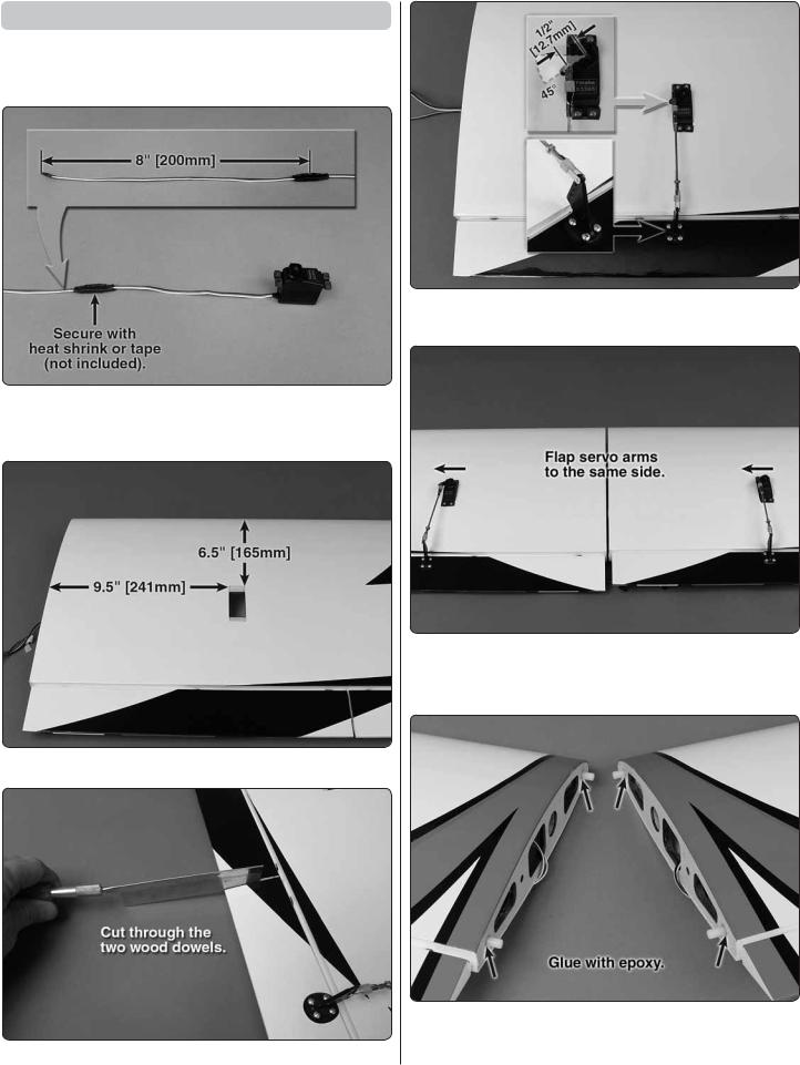
Flap Servo Installation (Optional)
Flaps are not necessary to land the 30cc Escapade. However, if you have never fl own with fl aps, the 30cc Escapade is a great plane to learn with.
1. Install a servo lead extension (not included).
2. Install grommets and eyelets in the fl ap servo .
3. Remove the covering from fl ap servo opening.
4. Separate the fl ap from the aileron.
5. Install the flap servo following the same procedure used to install the aileron servos.
6. Install the fl ap servo in the right wing. The two fl ap servos are connected with a Y-harness and plugged into the fl ap channel on the receiver.
7. Install the nylon wing dowels.
9
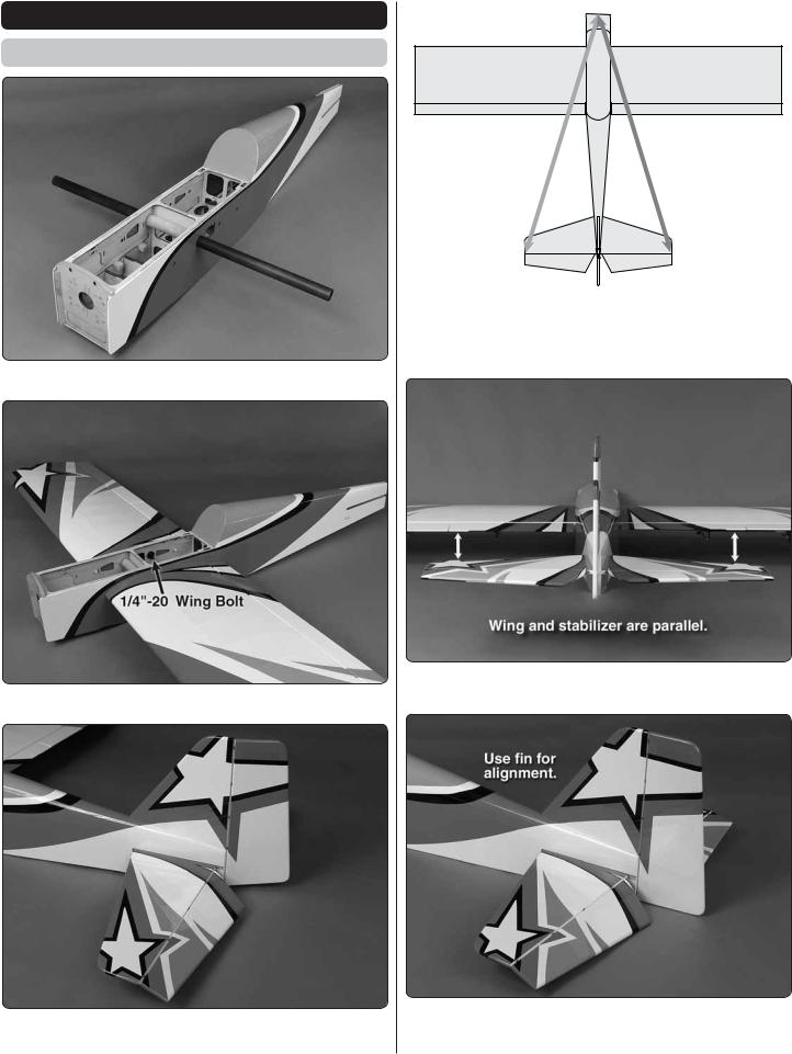
ASSEMBLE THE FUSELAGE
Install the Tail
1. Slide the Carbon Wing Tube into the fuselage.
2. Install the wing panels.
3. Temporarily install the horizontal stabilizer and the vertical fi n.
A A
A = A
5. Check the alignment of the horizontal stabilizer. The distance from the center of the nose of the fuselage to the tips of the horizontal stabilizer should be equal.
The wing and stabilizer should be parallel. If they are not, lightly sand the stabilizer slot.
10
 Loading...