


™
INSTRUCTION MANUAL
Wingspan: 52.5 in [1340mm] Wing Area: 483 in2 [31.2dm2] Weight: 5.0 – 5.5 lb [2270 – 2495g]
Wing Loading: 24 – 26 oz/ft2 [73 – 80g/dm2] Length: 46 in [1160mm]
Radio: 4-channel, 3 – 5 standard servos Engine: .40 – .55 cu in [6.5 – 9.0cc] 2-stroke glow,
.52 – .70 cu in [8.5 – 11.5cc] 4-stroke glow,
.46 RimFire™ (42-60-800kV), 14.8V (4S) 3200mAh LiPo, 60A ESC
WARRANTY
Great Planes® Model Manufacturing Co. guarantees this kit to be free from defects in both material and workmanship at the date of purchase. This warranty does not cover any component parts damaged by use or modification. In no case shall Great
Planes’ liability exceed the original cost of the purchased kit. Further, Great Planes reserves the right to change or modify this warranty without notice.
In that Great Planes has no control over the fi nal assembly or material used for fi nal assembly, no liability shall be assumed nor accepted for any damage resulting from the use by the user of the fi nal user-assembled product. By the act of using the user-assembled product, the user accepts all resulting liability.
If the buyer is not prepared to accept the liability associated with the use of this product, the buyer is advised to return this kit immediately in new and unused condition to the place of purchase.
To make a warranty claim send the defective part or item to Hobby Services at the address below:
Hobby Services
3002 N. Apollo Dr., Suite 1
Champaign, IL 61822 USA
Include a letter stating your name, return shipping address, as much contact information as possible (daytime telephone number, fax number, e-mail address), a detailed description of the problem and a photocopy of the purchase receipt. Upon receipt of the package the problem will be evaluated as quickly as possible.
READ THROUGH THIS MANUAL BEFORE STARTING CONSTRUCTION. IT CONTAINS IMPORTANT INSTRUCTIONS AND WARNINGS CONCERNING THE ASSEMBLY AND USE OF THIS MODEL.
Champaign, Illinois
(217) 398-8970, Ext 5 airsupport@greatplanes.com
Entire Contents © Copyright 2008 |
GPMA1200MNL V1.0 |
TABLE OF CONTENTS |
|
INTRODUCTION ............................................................... |
2 |
AMA .................................................................................. |
2 |
SAFETY PRECAUTIONS ................................................. |
2 |
DECISIONS YOU MUST MAKE........................................ |
3 |
Motor/Battery/ESC Recommendations ........................ |
3 |
Glow Engine Recommendations.................................. |
4 |
Radio Equipment.......................................................... |
4 |
ADDITIONAL ITEMS REQUIRED .................................... |
4 |
Optional Supplies & Tools ............................................ |
4 |
IMPORTANT BUILDING NOTES...................................... |
4 |
ORDERING REPLACEMENT PARTS .............................. |
5 |
METRIC CONVERSIONS ................................................. |
5 |
KIT INSPECTION.............................................................. |
6 |
KIT CONTENTS................................................................ |
6 |
PREPARATIONS............................................................... |
7 |
Tighten the Covering.................................................... |
7 |
ASSEMBLE THE WINGS.................................................. |
7 |
Hook Up the Ailerons (Single Servo Option)................ |
7 |
Hook Up the Ailerons (Dual Servo Option) .................. |
9 |
ASSEMBLE THE FUSELAGE ........................................ |
11 |
Hook Up the Elevator & Rudder................................. |
11 |
Mount the Main Landing Gear.................................... |
12 |
Mount the Electric Motor ............................................ |
13 |
Mount the Engine....................................................... |
14 |
Mount the Fuel Tank (or Motor Battery) ..................... |
15 |
Hook Up the Throttle .................................................. |
17 |
Two-Stroke Hookup.................................................... |
17 |
Four-Stroke Hookup................................................... |
17 |
FINAL ASSEMBLY ......................................................... |
19 |
Final Radio Installation............................................... |
19 |
Apply the Decals ........................................................ |
20 |
GET THE MODEL READY TO FLY ................................. |
20 |
Battery Precautions.................................................... |
20 |
Check the Control Directions ..................................... |
21 |
Set the Control Throws............................................... |
22 |
Balance the Model (C.G.)........................................... |
23 |
Balance the Model Laterally....................................... |
24 |
PREFLIGHT .................................................................... |
24 |
Identify Your Model ..................................................... |
24 |
Charge the Batteries .................................................. |
24 |
Balance Propellers..................................................... |
24 |
Ground Check & Range Check.................................. |
24 |
ENGINE SAFETY PRECAUTIONS................................. |
25 |
AMA SAFETY CODE (excerpts).................................... |
25 |
CHECK LIST................................................................... |
26 |
FLYING............................................................................ |
26 |
Takeoff........................................................................ |
26 |
Flight .......................................................................... |
27 |
Landing ...................................................................... |
27 |
INTRODUCTION
Thank you for purchasing the Great Planes Escapade ARF. The Escapade is a perfect “second airplane” for someone who is ready to move on from their high-wing trainer. The Escapade is also a great Sunday flyer for pilots who want to enjoy the simplicity and thrill of a “straight-forward” .40-size, low-wing sport model.
The Escapade may be powered by either a 2-stroke or 4-stroke glow engine, or electric motor. Installation instructions for each are detailed in this instruction manual. The Escapade also features the option of dual, outboard aileron servos or a single aileron servo mounted in the middle of the wing. Dual aileron servos will provide a little more precision and control response because the pushrods work directly on the ailerons. Additionally, response will be quicker.There will be more “power” connected to the ailerons because each one is operated by its own servo. But, if you prefer simplicity and economy, the single aileron servo will fl y the Escapade well.
For the latest technical updates or manual corrections to the Escapade ARF visit the Great Planes web site at www.greatplanes.com. Open the “Airplanes” link, then select the Escapade ARF. If there is new technical information or changes to this model a “tech notice” box will appear in the upper left corner of the page.
AMA
If you are not already a member of the AMA, please join! The AMA is the governing body of model aviation and membership provides liability insurance coverage, protects modelers’ rights and interests and is required to fl y at most R/C sites.
Academy of Model Aeronautics
5151 East Memorial Drive
Muncie, IN 47302-9252
Tele. (800) 435-9262
Fax (765) 741-0057 Or via the Internet at:
http://www.modelaircraft.org
IMPORTANT!!! Two of the most important things you can do to preserve the radio controlled aircraft hobby are to avoid fl ying near full-scale aircraft and avoid fl ying near or over groups of people.
PROTECT YOUR MODEL, YOURSELF & OTHERS....FOLLOW THESE IMPORTANT SAFETY PRECAUTIONS
1. Your Escapade should not be considered a toy, but rather a sophisticated, working model that functions very much like a full-size airplane. Because of its performance capabilities, the Escapade, if not assembled and operated correctly, could possibly cause injury to yourself or spectators and damage to property.
2.Youmustassemblethemodelaccordingtotheinstructions. Do not alter or modify the model, as doing so may result in an unsafe or unflyable model. In a few cases the instructions may differ slightly from the photos. In those instances the written instructions should be considered as correct.
2
3. You must take time to build straight, true and strong.
4.You must use an R/C radio system that is in good condition, a correctly sized engine, and other components as specifi ed in this instruction manual. All components must be correctly installed so that the model operates correctly on the ground and in the air.You must check the operation of the model and all components before every fl ight.
5. If you are not an experienced pilot or have not fl own this type of model before, we recommend that you get the assistance of an experienced pilot in your R/C club for your fi rst fl ights. If you’re not a member of a club, your local hobby shop has information about clubs in your area whose membership includes experienced pilots.
6.While this kit has been fl ight tested to exceed normal use, if the plane will be used for extremely high stress fl ying, such as racing, or if an engine larger than one in the recommended range is used, the modeler is responsible for taking steps to reinforce the high stress points and/or substituting hardware more suitable for the increased stress.
7.WARNING: The cowl and wheel pants included in this kit are made of fi berglass, the fi bers of which may cause eye, skin and respiratory tract irritation. Never blow into a part (wheel pant, cowl) to remove fi berglass dust, as the dust will blow back into your eyes. Always wear safety goggles, a particle mask and rubber gloves when grinding, drilling and sanding fi berglass parts. Vacuum the parts and the work area thoroughly after working with fi berglass parts.
We, as the kit manufacturer, provide you with a top quality, thoroughly tested kit and instructions, but ultimately the quality and fl yability of your fi nished model depends on how you build it; therefore, we cannot in any way guarantee the performance of your completed model, and no representations are expressed or implied as to the performance or safety of your completed model.
Remember:Take your time and follow the instructions to end up with a well-built model that is straight and true.
DECISIONS YOU MUST MAKE
This is a partial list of items required to fi nish the Escapade that may require planning or decision making before starting to build. Order numbers are provided in parentheses.
The most important decision you may be thinking about is whether to go electric or glow. Here are some considerations that may help you:
Almost always, glow power provides the longest fl ight times (in the Escapade, approximately 12 minutes with a glow engine and approximately 6 – 8 minutes with electric motor). Usually, it is an achievement if one can get the power of an electric motor to equal that of a comparable glow engine.
Of course, with glow motors there is never any waiting for batteries to charge (it takes one hour to charge a LiPo battery). You may purchase multiple batteries and charge them at home the evening before you go fl ying, but then the number of consecutive fl ights will be limited by the number of battery packs you own—and battery packs (and all the associated chargers, power supplies, cell balancers, connectors) can be expensive. Finally, with a glow engine, it is usually easier to accurately determine your fl ight time. Sometimes, with electric motors, fl ight times can be inconsistent due to the number of variables that can have an effect on a battery’s condition, thus causing fl ights to end sooner than expected.
However, glow engines are messy. With an electric motor, there will never be any oily exhaust residue to clean off the model. Electric motors are easier on the airframe because there is little vibration (and again, no fuel or oily exhaust residue that can leak into the structure). Electric motors are simple to operate—they don’t require starting (other than advancing the throttle stick on your transmitter!). Over the long haul, and depending on how much you fl y, electric motors can be more economical than glow because you’ll never have to buy fuel (although, most LiPo batteries have a life cycle of approximately two years). Finally, electric motors are pure and quiet.
Motor vs. Engine
An engine is a device that converts heat energy (in a fuel) into mechanical energy that can do work. A motor is powered by electricity or a mechanism (such as a spring in a wrist watch).
Motor/Battery/ESC Recommendations
If powering your Escapade with an electric motor, it performs superbly on a RimFire™ .46 motor (GPMG4725) and a single, 4S (four, single cells) 3200mAh 14.8V LiPo battery.If experimenting with different batteries, make certain they are rated for at least a 20C discharge (as is the recommended battery).
A 60A ESC (electronic speed controller) is also required.The Great Planes Silver Series 60A Brushless ESC (GPMM1850) is recommended.
Following are the other suggested items if powering your Escapade with an electric motor:
Suitable propeller and spare propellers (APC 12" x 6" thin electric propeller – APCQ4130)
12V power supply (Hobbico® 12 Volt Power Supply
– HCAP0250)
Adhesive-backed Velcro® (GPMQ4480)
LiPo battery charger (Great Planes PolyCharge4™ DC LiPo charger – GPMM3015)
(1) Great Planes ElectriFly Equinox™ LiPo Cell Balancer (GPMM3160) for each battery to be charged simultaneously
3
(1) Great Planes ElectriFly Equinox 4S/5S 4S adapter set for each Equinox balancer (GPMM3162)
8mm prop reamer (for propellers and included spinner
– GPMQ5007)
Great Planes Pro™ 30-minute epoxy (GPMR6043) (for gluing motor mount to fuselage)
IMPORTANT: The Escapade requires a single, 4S battery pack. But if experimenting with different battery combinations and connecting multiple battery packs with adapter plugs, refer to the Battery Precautions on page 20.
Glow Engine Recommendations
The recommended glow engine size range for the Escapade is printed on the cover of this instruction manual. It will fl y well with any of the engines within the recommended range. And, the Escapade is a lightweight model, so when fl own with engines even at the smaller end of the scale it will still be fast and responsive. So, unless you are an experienced pilot, you may be better off starting out with a smaller engine.
In addition to the engine, following are the additional items required if powering your Escapade with a glow engine:
Suitable propeller and spare propellers
Fuel, fueling system (pump, fuel line, fuel can fi ttings set), 1.5V glow driver, fi eld box, tools
#36 (or 7/64) [2.6mm] drill
Optional: 6-32 tap and drill set (GPMR8102), (4) 6-32 x 1" socket-head cap screws (GPMQ3038) for mounting engine with machine screws instead of included sheetmetal screws.
Radio Equipment
4-channels are required to fl y the Escapade. However, the number of servos required can be from three to fi ve. Only three channels will be required if fl ying the Escapade with an electric motor and using the single aileron servo option. If powering the model with a glow engine, a servo will be required for the throttle. And in either case (glow or electric), two servos will be required for the ailerons if using the dual aileron servo option. In all cases, standard-size servos with standard output torque (40 – 50 oz-in torque) are suitable.
Following is the specific radio gear required for the different configurations:
For all versions;
4-channel radio system w/4.8V 500-600mAh fl at Rx battery back, on/off switch
1 ea. standard size/torque elevator and rudder servo
For single aileron servo option:
(1) standard torque/size aileron servo
(2) 6" [150mm] servo extension wires (HCAM2000)
For dual aileron servo option:
(2) standard torque/size aileron servos
(2) 6" [150mm] servo extension wires (HCAM2000 for Futaba®)
(1) Dual servo extension (FUTM4130 for Futaba)
ADDITIONAL ITEMS REQUIRED
Inadditiontocommonhobbytools(screwdrivers,pliers,wire cutters), following is a list of suggested building supplies:
1/2 oz. [15g] Medium Pro™ CA+ (GPMR6007)
1/2 oz. [15g] Thin Pro CA (GPMR6001)
CA applicator tips (HCAR3780)
#1 Hobby knife (HCAR0105)
#11 Blades (5-pack, HCAR0211)
Power drill
Drill bits; 1/16" [1.6mm], 3/32" [2.4mm], #48 (.076" [1.9mm])
drill or hobby knife
Great Planes Pro Threadlocker (GPMR6060)
21st Century® sealing iron (COVR2700)
Optional Supplies & Tools
Here is a list of optional tools mentioned in the manual that will help you build the Escapade.
21st Century iron cover (COVR2702)
21st Century trim seal iron (COVR2750)
Stick-on segmented lead weights (GPMQ4485)
2 oz. [57g] Spray CA activator (GPMR6035)
Dead Center™ Engine Mount Hole Locator (GPMR8130)
C.G. Machine™ (GPMR2400)
Precision Magnetic Prop Balancer™ (TOPQ5700)
IMPORTANT BUILDING NOTES
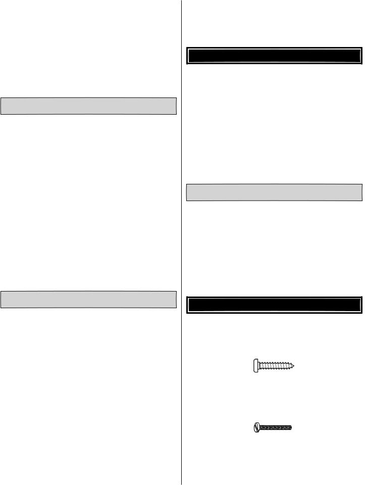
•There are two types of screws used in this kit:
•Sheet Metal Screws are designated by a number and a length. For example #6 x 3/4" [19mm].
This is a number six screw that is 3/4" [19mm] long.
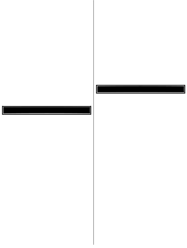
•Machine screws are designated by a number, threads per inch, and a length. For example 4-40 x 3/4" [19mm]
This is a number 4 screw that is 3/4" [19mm] long with forty threads per inch.
•The Escapade is factory-covered with Top Flite® MonoKote® fi lm. Should repairs ever be required, MonoKote can be patched with additional MonoKote
4
purchased separately. MonoKote is packaged in six-foot rolls, but some hobby shops also sell it by the foot. If only a small piece of MonoKote is needed for a minor patch, perhaps a fellow modeler would give you some. MonoKote is applied with a model airplane covering iron, but in an emergency a regular iron could be used. A roll of MonoKote includes full instructions for application. Following are the colors used on this model and order numbers for six foot rolls.
Jet White – TOPQ0204
Orange – TOPQ0202
True Red – TOPQ0227
•The stabilizer and wing incidences and engine thrust angles have been factory-built into this model. However, some technically-minded modelers may wish to check these measurements anyway. To view this information visit the web site at www.greatplanes.com and click on “Technical Data.” Due to manufacturing tolerances which will have little or no effect on the way your model will fl y, please expect slight deviations between your model and the published values.
ORDERING REPLACEMENT PARTS
Replacement parts for the Great Planes Escapade ARF are available using the order numbers in the Replacement Parts List that follows. The fastest, most economical service can be provided by your hobby dealer or mail-order company.
To locate a hobby dealer, visit the Hobbico web site at www.hobbico.com. Choose “Where to Buy” at the bottom of the menu on the left side of the page. Follow the instructions provided on the page to locate a U.S., Canadian or International dealer.
Parts may also be ordered directly from Hobby Services by calling (217) 398-0007, or via facsimile at (217) 398-7721, but full retail prices and shipping and handling charges will apply. Illinois and Nevada residents will also be charged sales tax. If ordering via fax, include a Visa® or MasterCard® number and expiration date for payment.
Mail parts orders and payments by personal check to:
Hobby Services
3002 N. Apollo Drive, Suite 1
Champaign, IL 61822
Be certain to specify the order number exactly as listed in the Replacement Parts List. Payment by credit card or personal check only; no C.O.D.
IfadditionalassistanceisrequiredforanyreasoncontactProduct Support by e-mail at productsupport@greatplanes.com, or by telephone at (217) 398-8970.
Replacement Parts List
Description |
How to Purchase |
Missing pieces |
Contact Product Support |
Instruction manual |
Contact Product Support |
Full-size plans |
Not available |
Contact your hobby supplier for the following parts:
GPMA3250 |
Fuselage |
GPMA3251 |
Wing |
GPMA3252 |
Tail Surface Set |
GPMA3253 |
Landing Gear |
GPMA3254 |
Wheel Pants |
GPMA3255 |
Wing Joiner |
GPMA3256 |
Canopy/Hatch |
GPMA3257 |
Decal |
GPMA3258 |
Out-runner Mount |
GPMA3259 |
OPTIONAL Fiberglass Cowl |
METRIC CONVERSIONS
1" = 25.4mm (conversion factor)
1/64" |
= .4mm |
3/4" |
= 19.0mm |
1/32" |
= .8mm |
1" |
= 25.4mm |
1/16" |
= 1.6mm |
2" |
= 50.8mm |
3/32" |
= 2.4mm |
3" |
= 76.2mm |
1/8" |
= 3.2mm |
6" |
= 152.4mm |
5/32" |
= 4.0mm |
12" |
= 304.8mm |
3/16" |
= 4.8mm |
18" |
= 457.2mm |
1/4" |
= 6.4mm |
21" |
= 533.4mm |
3/8" |
= 9.5mm |
24" |
= 609.6mm |
1/2" |
= 12.7mm |
30" |
= 762.0mm |
5/8" |
= 15.9mm |
36" |
= 914.4mm |
5
KIT INSPECTION
Before starting to build, take an inventory of this kit to make sure it is complete and inspect the parts to make sure they are of acceptable quality. If any parts are missing or are not of acceptable quality, or if you need assistance with assembly, contact Product Support. When reporting defective or missing parts, use the part names exactly as they are written in the Kit Contents list.
Great Planes Product Support: 3002 N Apollo Drive, Suite 1 Champaign, IL 61822 Telephone: (217) 398-8970, ext. 5 Fax: (217) 398-7721
E-mail: airsupport@greatplanes.com
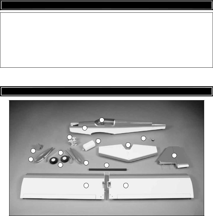
KIT CONTENTS
|
|
2 |
|
|
1 |
|
7 |
9 |
|
|
|
|
|
8 |
|
|
10 |
3 |
|
|
5 |
|
11 |
|
|
|
4 |
|
5 |
6 |
|
|
|
12 |
13 |
14 |
|
|
Kit Contents |
|
||
1 |
Fuselage |
|
|
8 |
Fuel Tank |
|
|||||
2 |
Canopy |
|
|
9 |
Tail Gear Assembly |
3 |
Spinner |
|
|
10 |
Horizontal Stabilizer & Elevators |
4 |
Wheel Pants (L&R) |
|
|
11 |
Vertical Stabilizer (Fin) & Rudder |
5 |
Main Landing Gear (L&R) |
|
|
12 |
Aluminum Wing Joiner Tube |
6 |
Main Wheels (2) |
|
|
13 |
Left Wing Panel w/Aileron |
7 |
Motor Mount |
|
|
14 |
Right Wing Panel w/Aileron |
|
|
|
|
|
|
6

PREPARATIONS
Tighten the Covering
Refer to the separate instruction sheet titled How To Tighten Covering On ARF Models. Follow the instructions to tighten the covering. If you prefer to get started on assembly right away, the tightening process could be done later (but it is usually easiest to do while the model is still in separate pieces).
ASSEMBLE THE WINGS
Hook Up the Ailerons (Single Servo Option)
If using dual aileron servos, skip to the next section on page 9.
1. Place your aileron servo in the servo mount built into the right wing half (note the servo wire coming out between the right side of the servo and the mount). Drill 1/16" [1.6mm] holes for the servo mounting screws.
2. Temporarily mount the servo with the screws that came with it. Remove the screws and take out the servo. Add a few drops of thin CA to each screw hole. Wait a minute for the CA to harden and re mount the servo (guiding the wire between the right side of the servo and the servo mount). Don’t overtighten the servo mounting screws—just make sure the heads of the screws apply a little pressure to the grommets and that the servo is secure.
3. Temporarily connect the aileron servo to your receiver with a battery and on/off switch. Turn on the transmitter and receiver and center all the trims on the transmitter.
CUT OFF THE
YES 90° UNUSED ARMS
4. With the radio on, position the servo arm on the splined output shaft on the servo so it will be 90-degrees as shown in the sketch. Once you find the orientation that’s 90-degrees, cut off the other two unused arms. The radio may now be turned off, disconnected from the aileron servo and set aside.
7
TORQUE ROD HORN
AILERON TORQUE ROD
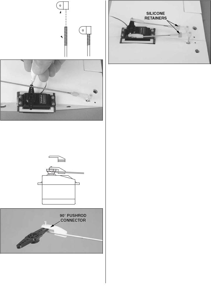
5. Screw a torque rod horn onto the right aileron torque rod so that the top of the horn is even with the top of the torque rod. Temporarily fi t the clevis on the end of one of the shorter pushrod wires for the ailerons onto the horn. Use a fi ne-point felt-tip pen to mark the pushrod wire where it crosses the outer hole in the servo arm.
90° PUSHROD CONNECTOR
6. Disconnect the pushrod from the torque rod horn and make a sharp, 90° bend in the wire at the mark. Enlarge the holes in the aileron servo arm with a #48 (.076" [1.9mm]) drill or a hobby knife. Fit the pushrod into the outer hole in the servo arm, then attach a 90° pushrod connector to the assembly. Cut the excess wire 1/16" [2mm] above the connector.
7. Temporarily join the wings with the aluminum wing joiner tube. Connect the other aileron pushrod the same way you did the fi rst one. Install the servo arm screw and slip the silicone retainers over the pushrod.
8. When it’s time to join the wings for fl ying, mount the strap to the wings as shown in step 12 on page 11. When you want to separate the wing halves, simply disconnect the clevis on the left aileron pushrod from the torque rod horn, and then slide the wings apart.
Later, during fi nal radio and control throws set up, the pushrods will be adjusted so the ailerons are centered when the radio is on (or, you could reconnect your aileron servo to the radio and do this now).
Proceed to Assemble the Fuselage.
8
Hook Up the Ailerons (Dual Servo Option)
You can do both servos simultaneously, or do them one at a time as described below:

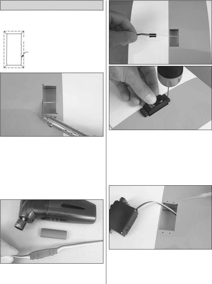
 SERVO OPENING
IN WING
CUT THE COVERING 1/8" [3mm]
FROM THE EDGES OF THE OPENING.
SLIT THE COVERING UP TO THE
CORNERS.
1. Cut the covering from one (or both) of the aileron servo openings in the bottom of the wings. The “neatest” way is to cut the covering 1/8" [3mm] inside the opening, cut slits up to the corners, and then use a trim iron to seal the edges down inside the openings. Or, just cut the covering up to the edges.
2. Connect a 6" [150mm] servo extension to the aileron servo and secure the connection with a 1-1/2" [40mm] piece of heat shrink tubing included with this kit—shrink the tubing with a heat gun or a hobby torch—use care not to scorch the wires!
3. Use the string in the wing to pull the servo extension out the end and place the aileron servo in the wing. Drill 1/16" [1.6mm] holes for the servo mounting screws.
4. Temporarily mount the servo with the screws that came with it. Remove the screws and take out the servo. Add a few drops of thin CA to each screw hole. Wait a minute for the CA to harden and remount the servo. Don’t overtighten the servo mounting screws—just make sure the heads of the screws apply a little pressure to the grommets and that the servo is secure.
9
 Loading...