


INSTRUCTION MANUAL
Wingspan: 60 in [1520mm] Wing Area: 606 in2 [39dm2]
Weight: 6.75 – 7.25 lb [3060 – 3290g] Wing Loading: 26 – 28 oz/ft2 [79 – 85g/dm2] Length: 46 in [1170mm]
Radio: 4-channel minimum with four to seven standard servos and standard size receiver
Engine: .40 – .46 cu in [7 – 7.5cc] two-stroke,
.56 cu in [9.2cc] four-stroke, 42-50-800kV brushless out-runner motor
WARRANTY
Great Planes® Model Manufacturing Co. guarantees this kit to be free from defects in both material and workmanship at the date of purchase. This warranty does not cover any component parts damaged by use or modification. In no case shall Great Planes’ liability exceed the original cost of the purchased kit. Further, Great Planes reserves the right to change or modify this warranty without notice.
In that Great Planes has no control over the fi nal assembly or material used for fi nal assembly, no liability shall be assumed nor accepted for any damage resulting from the use by the user of the fi nal user-assembled product. By the act of using the user-assembled product, the user accepts all resulting liability.
If the buyer is not prepared to accept the liability associated with the use of this product, the buyer is advised to return this kit immediately in new and unused condition to the place of purchase.
To make a warranty claim send the defective part or item to Hobby Services at the address below:
Hobby Services
3002 N. Apollo Dr., Suite 1
Champaign, IL 61822 USA
Include a letter stating your name, return shipping address, as much contact information as possible (daytime telephone number, fax number, e-mail address), a detailed description of the problem and a photocopy of the purchase receipt. Upon receipt of the package the problem will be evaluated as quickly as possible.
READ THROUGH THIS MANUAL BEFORE STARTING CONSTRUCTION. IT CONTAINS IMPORTANT INSTRUCTIONS AND WARNINGS CONCERNING THE ASSEMBLY AND USE OF THIS MODEL.
Champaign, Illinois
(217) 398-8970, Ext 5 airsupport@greatplanes.com
Entire Contents © Copyright 2008 |
GPMZ1033 for GPMA1033 V1.0 |

TABLE OF CONTENTS |
|
|
INTRODUCTION ................................................................................ |
|
2 |
AMA ................................................................................................... |
|
2 |
SAFETY PRECAUTIONS .................................................................. |
|
2 |
DECISIONS YOU MUST MAKE......................................................... |
|
3 |
Radio Equipment.......................................................................... |
|
3 |
Power System Recommendations ............................................... |
|
3 |
Propeller....................................................................................... |
|
4 |
Batteries & Charger...................................................................... |
|
4 |
ADDITIONAL ITEMS REQUIRED ..................................................... |
|
4 |
Required Hardware & Accessories .............................................. |
|
4 |
Adhesives & Building Supplies..................................................... |
|
4 |
Optional Supplies & Tools ............................................................ |
|
4 |
BUILDING STAND ............................................................................. |
|
5 |
IMPORTANT BUILDING NOTES....................................................... |
|
5 |
ORDERING REPLACEMENT PARTS ............................................... |
|
5 |
COMMON ABBREVIATIONS ............................................................ |
|
6 |
METRIC CONVERSIONS .................................................................. |
|
6 |
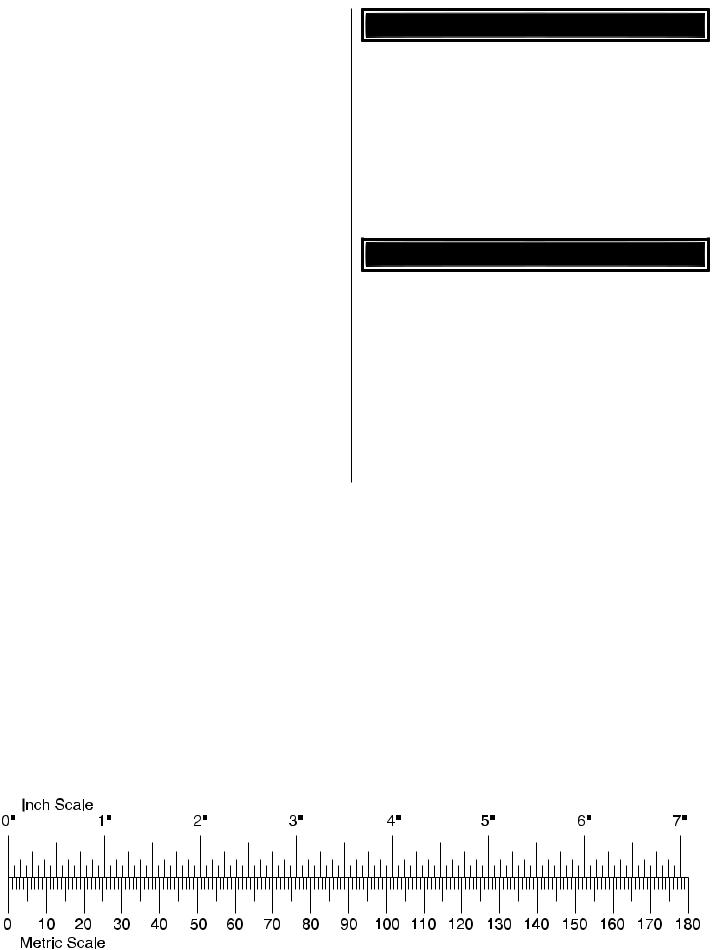
METRIC/INCH RULER....................................................................... |
|
6 |
KIT INSPECTION............................................................................... |
|
7 |
KIT CONTENTS................................................................................. |
|
7 |
PREPARATIONS................................................................................ |
|
8 |
BUILD THE WING PANELS ............................................................... |
|
8 |
Install the Aileron & Flap Servos & Pushrods .............................. |
|
8 |
Fixed Flaps................................................................................. |
|
11 |
BUILD THE FUSELAGE ................................................................. |
|
11 |
Install the Tail Surfaces............................................................... |
|
11 |
Install the Tail Servos & Pushrods.............................................. |
|
12 |
Glow Engine Installation............................................................. |
|
13 |
Brushless Motor Installation ....................................................... |
|
16 |
Assemble & Install the Landing Gear......................................... |
|
18 |
FINISH THE MODEL........................................................................ |
|
20 |
Install the Receiver..................................................................... |
|
20 |
Install the Cowl, Spinner & Propeller.......................................... |
|
21 |
Install the Wing & Canopy Hatch................................................ |
|
22 |
Apply the Decals ........................................................................ |
|
22 |
GET THE MODEL READY TO FLY .................................................. |
|
22 |
Install and Operate the Motor Battery (Brushless Only)............. |
22 |
|
Battery Precautions/Connecting Batteries ................................. |
|
23 |
Check the Control Directions ..................................................... |
|
23 |
Set the Control Throws............................................................... |
|
23 |
Balance the Model (C.G.)........................................................... |
|
24 |
Balance the Model Laterally....................................................... |
|
25 |
PREFLIGHT ..................................................................................... |
|
25 |
Identify Your Model ..................................................................... |
|
25 |
Charge the Batteries .................................................................. |
|
25 |
Balance Propellers ..................................................................... |
|
25 |
Ground Check ............................................................................ |
|
25 |
Range Check ............................................................................. |
|
25 |
ENGINE SAFETY PRECAUTIONS.................................................. |
|
26 |
LITHIUM BATTERY HANDLING & USAGE .................................... |
|
26 |
AMA SAFETY CODE (excerpts)..................................................... |
|
26 |
CHECK LIST.................................................................................... |
|
27 |
FLYING............................................................................................. |
|
27 |
Fuel Mixture Adjustments........................................................... |
|
27 |
Takeoff........................................................................................ |
|
27 |
Flight .................................................................. |
Back Cover Page |
|
Landing .............................................................. |
Back Cover Page |
|
Flaps .................................................................. |
Back Cover Page |
|
INTRODUCTION |
|
|
Congratulations on your purchase of the Great Planes Cherokee .40 ARF! We have designed this plane to be a quick, fuss-free build by minimizing the amount of glue and measuring that needs to be done for a typical ARF. With a bolt-on, self-aligning tail section along with many other small time-consuming tasks already complete, you can have your Cherokee .40 ARF built in as little as 4 to 6 hours. Just like its full-scale counterpart, the Cherokee .40 ARF is extremely
easy to fly and would be appropriate for beginners who have mastered a trainer or for the veteran pilot who just appreciates the rich history of the Cherokee.
For the latest technical updates or manual corrections to the Cherokee .40 ARF visit the Great Planes web site at www.greatplanes.com. Open the “Airplanes” link, then select the Cherokee .40 ARF. If there is new technical information or changes to this model, a “tech notice” box will appear in the upper left corner of the page.
AMA
We urge you to join the AMA (Academy of Model Aeronautics) and a local R/C club.The AMA is the governing body of model aviation and membership is required to fly at AMA clubs. Though joining the AMA provides many benefits, one of the primary reasons to join is liability protection. Coverage is not limited to flying at contests or on the club field. It even applies to flying at public demonstrations and air shows. Failure to comply with the Safety Code (excerpts printed in the back of the manual) may endanger insurance coverage. Additionally, training programs and instructors are available at AMA club sites to help you get started the right way. There are over 2,500 AMA chartered clubs across the country. Contact the AMA at the address or toll-free phone number below:
Academy of Model Aeronautics
5151 East Memorial Drive
Muncie, IN 47302-9252
Tele. (800) 435-9262
Fax (765) 741-0057 Or via the Internet at:
http://www.modelaircraft.org
IMPORTANT!!! Two of the most important things you can do to preserve the radio controlled aircraft hobby are to avoid fl ying near full-scale aircraft and avoid fl ying near or over groups of people.
PROTECT YOUR MODEL, YOURSELF & OTHERS....FOLLOW THESE IMPORTANT SAFETY PRECAUTIONS
1. Your Cherokee .40 ARF should not be considered a toy, but rather a sophisticated, working model that functions very much like a full-size airplane. Because of its performance capabilities, the Cherokee .40 ARF, if not assembled and operated correctly, could possibly cause injury to yourself or spectators and damage to property.
2.You must assemble the model according to the instructions. Do not alter or modify the model, as doing so may result in an unsafe or unflyable model. In a few cases the instructions may differ slightly from the photos. In those instances the written instructions should be considered as correct.
2
3.You must take time to build straight, true and strong.
4.You must use an R/C radio system that is in first-class condition, and a correctly sized engine and components throughout the building process.
5.You must correctly install all R/C and other components so that the model operates correctly on the ground and in the air.
6.You must check the operation of the model before every fl ight to insure that all equipment is operating and that the model has remained structurally sound. Be sure to check clevises or other connectors often and replace them if they show any signs of wear or fatigue.
7.If you are not an experienced pilot or have not flown this type of model before, we recommend that you get the assistance of an experienced pilot in your R/C club for your fi rst fl ights. If you’re not a member of a club, your local hobby shop has information about clubs in your area whose membership includes experienced pilots.
8.While this kit has been flight tested to exceed normal use, if the plane will be used for extremely high stress flying, such as racing, or if an engine larger than one in the recommended range is used, the modeler is responsible for taking steps to reinforce the high stress points and/or substituting hardware more suitable for the increased stress.
9.WARNING: The cowl and wheel pants included in this kit are made of fiberglass, the fibers of which may cause eye, skin and respiratory tract irritation. Never blow into a part to remove fi berglass dust, as the dust will blow back into your eyes. Always wear safety goggles, a particle mask and rubber gloves when grinding, drilling and sanding fiberglass parts. Vacuum the parts and the work area thoroughly after working with fi berglass parts.
We, as the kit manufacturer, provide you with a top quality, thoroughly tested kit and instructions, but ultimately the quality and flyability of your fi nished model depends on how you build it; therefore, we cannot in any way guarantee the performance of your completed model, and no representations are expressed or implied as to the performance or safety of your completed model.
Remember:Take your time and follow the instructions to end up with a well-built model that is straight and true.
DECISIONS YOU MUST MAKE
This is a partial list of items required to finish the Cherokee
.40 ARF that may require planning or decision making before starting to build. Order numbers are provided in parentheses.
Radio Equipment
The Cherokee .40 ARF requires a minimum 4-channel radio system with four to seven 44 oz.-in. [3.2 kg-cm] minimum standard servos. Operational fl aps will require six servos. If you are installing a glow engine, an additional standard servo is required for the throttle.
In addition, two 9" [229mm] servo extensions are required for the aileron servos. If you are using a radio system that does not support mixing functions, two Y-harnesses will also be required to connect the aileron servos and fl ap servos to the receiver.
Achargejackreceptacleisoptional,butisusefulforrecharging the receiver pack without removing the canopy hatch and is shown in the assembly of the plane. Recommended part numbers for the radio components are provided below:
Futaba® S3003 Servo Standard (FUTM0031)
Futaba S9001 Servo Aircraft Coreless BB (optional, FUTM0075)
Futaba 9" Servo Extension J (FUTM3910)
Futaba 6" Dual Servo Extension J (FUTM4130)
Ernst Charge Receptacle Futaba J FM (ERNM3001)
Power System Recommendations
The recommended engine/motor size for the Cherokee .40 ARF is a .40 to .46 cu in [7 to 7.5cc] two-stroke engine, .56 cu in [9.2cc] four-stroke engine, or a RimFire™ 42-50-800kV brushless out-runner motor. If installing a two-stroke glow engine, a Pitts muffl er is recommended. The stock muffl er can also be used with a muffl er extension but additional modifi cation to the fuselage and cowl would be necessary. Engine and motor order numbers are provided below:
O.S.® .46 AX ABL w/Muffl er (OSMG0547)
Bisson O.S. .46 SF/FX .50 SX Pitts Muffl er (BISG4046)
O.S. Muffl er Extension #873 (OSMG2578) (Stock muffl er only)
Great Planes RimFire 42-50-800 out-runner brushless (GPMG4700)
Great Planes Brushless Motor Mount Medium Motors (GPMG1255)
3
If using the recommended brushless motor, a 60A brushless ESC is required:
Great Planes Silver Series 60A brushless ESC high volt (GPMM1850)
Propeller
If you are installing a glow engine, choose a prop based on the engine manufacturer’s recommendation. If you are installing the recommended RimFire brushless motor, we suggest a 10" x 5 E or 11" x 5.5 E APC propeller. The 10" x 5 E prop provides adequate power with a longer flight time. The 11" x 5.5 E provides excellent power for the Cherokee .40 ARF at the cost of a shorter fl ight time.
APC 10" x 5 electric propeller (APCQ4120)
APC 11" x 5.5 electric propeller (APCQ1055)
Batteries & Charger
For a brushless motor installation, one 3200mAh 11.1V LiPo battery pack and one 3200mAh 7.4V LiPo battery pack connected in series are recommended. Order numbers for the battery packs and series connector are provided below:
Great Planes LiPo 7.4V 3200mAh 20C discharge w/balance (GPMP0622)
Great Planes LiPo 3200mAh 11.1V 20C discharge w/balance (GPMP0623)
Great Planes Series Deans® U 2 to 1 adapter (GPMM3143)
A cell balancer is required for the LiPo battery packs listed above:
Great Planes ElectriFly Equinox™ LiPo cell balancer 1to 5 (GPMM3160)
A suitable charger is also required. The Great Planes PolyCharge4™ is designed for LiPo packs only; however, it is able to charge four LiPo packs simultaneously. The Great Planes Triton2™ charger will only charge one pack at a time; however, it is capable of charging NiCd, NiMH, LiPo, and lead acid batteries. Order numbers for both are provided below:
Great Planes PolyCharge4 DC only 4 output LiPo charger (GPMM3015)
-or-
Great Planes ElectriFly Triton2 DC comp peak charger (GPMM3153)
ADDITIONAL ITEMS REQUIRED
Required Hardware & Accessories
This is the list of hardware and accessories required to fi nish the Cherokee .40 ARF. Order numbers are provided in parentheses:
R/C foam rubber 1/4" [6mm] (HCAQ1000)
3' [900mm] standard silicone fuel tubing (GPMQ4131) (glow engine installation only)
Adhesives & Building Supplies
This is the list of Adhesives and Building Supplies that are required to fi nish the Cherokee .40 ARF:
1/2 oz. [15g] Thin Pro CA (GPMR6001)
Pro™ 30-minute epoxy (GPMR6047)
Masking tape (TOPR8018)
Threadlocker threadlocking cement (GPMR6060)
Denatured alcohol (for epoxy clean up)
Drill bits: 1/16" [1.6mm], 5/64" [2mm], 3/32" [2.4mm],
3/16" [4.8mm]
Dead Center™ engine mount hole locator (GPMR8130) (glow engine installation only)
Great Planes tap & drill set 6-32 (GPMR8102) (glow engine installation only)
Tap handle (GPMR8120) (glow engine installation only)
Small metal fi le
#1 Hobby knife (HCAR0105)
#11 Blades (5-pack, HCAR0211)
Medium T-pins (100, HCAR5150)
Top Flite® MonoKote® sealing iron (TOPR2100)
Top Flite Hot Sock™ iron cover (TOPR2175)
220-grit Sandpaper (glow engine installation only)
Great Planes Velcro Hook & Loop 1" x 6" (2) (GPMQ4480) (brushless installation only)
Panel line pen (TOPQ2510)
Optional Supplies & Tools
Here is a list of optional tools that will help you build the Cherokee .40 ARF:
1/2 oz. [15g] Thick Pro CA- (GPMR6013)
2 oz. [57g] Spray CA activator (GPMR6035)
4 oz. [113g] Aerosol CA activator (GPMR6034)
CA applicator tips (HCAR3780)
CA debonder (GPMR6039)
Pro 6-minute epoxy (GPMR6045)
Epoxy brushes 6, (GPMR8060)
Mixing sticks (GPMR8055)
Mixing cups (GPMR8056)
4
Pliers with wire cutter (HCAR0630)
Hobbico Duster™ can of compressed air (HCAR5500)
Switch & Charge jack mounting set (GPMM1000)
Rotary tool such as Dremel®
Rotary tool reinforced cut-off wheel (GPMR8020)
Servo horn drill (HCAR0698)
Hobby Heat™ micro torch II (HCAR0755)
Precision magnetic prop balancer (TOPQ5700)
AccuThrow™ defl ection gauge (GPMR2405)
C.G. Machine™ (GPMR2400)
Hobbico fl exible 18" ruler stainless steel (HCAR0460)
Top Flite MonoKote trim seal iron (TOPR2200)
Top Flite MonoKote heat gun (TOPR2000)
Hobbico pin vise 1/16" collet w/6 Bits (HCAR0696)
Hobbico 8-piece ball tip hex L wrench SAE (HCAR0520)
Hobbico 7-piece ball tip hex L wrench Metric (HCAR0521)
Great Planes clevis installation tool (GPMR8030)
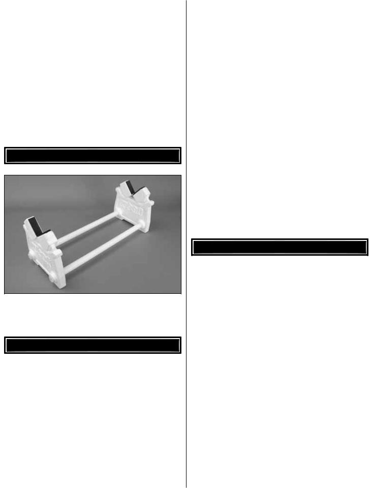
BUILDING STAND
A building stand or cradle comes in handy during the build. We use the Robart Super Stand II (ROBP1402) for all our projects in R&D, and it can be seen in pictures throughout this manual.
IMPORTANT BUILDING NOTES
•When you see the term test fit in the instructions, it means that you should first position the part on the assembly without using any glue, then slightly modify or custom fit the part as necessary for the best fit.
•Whenever the term glue is written you should rely upon your experience to decide what type of glue to use. When a specific type of adhesive works best for that step, the instructions will make a recommendation.
•Whenever just epoxy is specifi ed you may use either 30-minute (or 45-minute) epoxy or 6-minute epoxy. When 30-minute epoxy is specified it is highly recommended that you use only 30-minute (or 45-minute) epoxy, because you will need the working time and/or the additional strength.
•Photos and sketches are placed before the step they refer to. Frequently you can study photos in following steps to get another view of the same parts.
•The stabilizer and wing incidences and engine thrust angles have been factory-built into this model. However, some technically-minded modelers may wish to check these measurements anyway. To view this information visit the web site at www.greatplanes.com and click on “Technical Data.” Due to manufacturing tolerances which will have little or no effect on the way your model will fly, please expect slight deviations between your model and the published values.
ORDERING REPLACEMENT PARTS
Replacement parts for the Great Planes Cherokee .40 ARF are available using the order numbers in the Replacement Parts List that follows. The fastest, most economical service can be provided by your hobby dealer or mail-order company.
To locate a hobby dealer, visit the Hobbico web site at www.hobbico.com. Choose “Where to Buy” at the bottom of the menu on the left side of the page. Follow the instructions provided on the page to locate a U.S., Canadian or International dealer.
Parts may also be ordered directly from Hobby Services by calling (217) 398-0007, or via facsimile at (217) 398-7721, but full retail prices and shipping and handling charges will apply. Illinois and Nevada residents will also be charged sales tax. If ordering via fax, include a Visa® or MasterCard® number and expiration date for payment.
Mail parts orders and payments by personal check to:
Hobby Services
3002 N. Apollo Drive, Suite 1
Champaign, IL 61822
Be certain to specify the order number exactly as listed in the Replacement Parts List. Payment by credit card or personal check only; no C.O.D.
5
If additional assistance is required for any reason contact Product Support by e-mail at productsupport@greatplanes.com, or by telephone at (217) 398-8970.
Replacement Parts List
Description |
How to Purchase |
Missing pieces |
Contact Product Support |
Instruction manual |
Contact Product Support |
Full-size plans |
Not available |
Contact your hobby supplier for the following parts:
GPMA3240 |
Wing |
GPMA3241 |
Fuselage |
GPMA3242 |
Vertical Stabilizer & Rudder |
GPMA3243 |
Horizontal Stabilizer & Elevator |
GPMA3244 |
Canopy/Hatch |
GPMA3245 |
Wheel Pants |
GPMA3246 |
Landing Gear |
GPMA3247 |
Cowl |
GPMA3248 |
Wing Tube |
GPMA3249 |
Decal Sheet |
COMMON ABBREVIATIONS
Stab = Horizontal Stabilizer Fin = Vertical Fin
LE = Leading Edge
TE = Trailing Edge
LG = Landing Gear Ply = Plywood
" = Inches mm = Millimeters
SHCS = Socket Head Cap Screw ESC = Electronic Speed Control
METRIC CONVERSIONS
1" = 25.4mm (conversion factor)
1/64" |
= .4mm |
3/4" |
= 19.0mm |
1/32" |
= .8mm |
1" |
= 25.4mm |
1/16" |
= 1.6mm |
2" |
= 50.8mm |
3/32" |
= 2.4mm |
3" |
= 76.2mm |
1/8" |
= 3.2mm |
6" |
= 152.4mm |
5/32" |
= 4.0mm |
12" |
= 304.8mm |
3/16" |
= 4.8mm |
18" |
= 457.2mm |
1/4" |
= 6.4mm |
21" |
= 533.4mm |
3/8" |
= 9.5mm |
24" |
= 609.6mm |
1/2" |
= 12.7mm |
30" |
= 762.0mm |
5/8" |
= 15.9mm |
36" |
= 914.4mm |
6

KIT INSPECTION
Before starting to build, take an inventory of this kit to make sure it is complete and inspect the parts to make sure they are of acceptable quality. If any parts are missing or are not of acceptable quality, or if you need assistance with assembly, contact Product Support. When reporting defective or missing parts, use the part names exactly as they are written in the Kit Contents list.
Great Planes Product Support: 3002 N. Apollo Drive, Suite 1 Champaign, IL 61822 Telephone: (217) 398-8970, ext. 5 Fax: (217) 398-7721
E-mail: airsupport@greatplanes.com
KIT CONTENTS
1
|
|
|
|
|
|
2 |
|
3 |
|
|
9 |
|
12 |
|
|
|
|
|
||
|
|
|
5 |
|
|
|
|
|
|
|
10 |
|
|
|
|
|
|
|
|
|
4 |
|
|
6 |
|
|
|
|
|
|
|
|
|
|
|
|
|
8 |
|
9 |
|
|
|
|
|
|
|
|
|
|
7 |
|
|
11 |
13 |
|
|
|
|
|
||
|
|
|
|
|
|
14 |
15 |
|
|
|
KIT CONTENTS |
|
|
1 |
Cowl |
|
2-1/2" [64mm] Wheels (3) |
|
|
10 |
|||
2 |
Fuselage |
|
11 |
Aluminum Wing Joiner Tube |
3 |
Spinner |
|
12 |
Horizontal Stabilizer & Elevator |
4 |
Fuel Tank |
|
13 |
Vertical Fin & Rudder |
5 |
Engine Mount |
|
14 |
Right Wing Panel w/Flap & Aileron |
6 |
Main Landing Gear (L&R) |
|
15 |
Left Wing Panel w/Flap & Aileron |
7 |
Nose Gear Wire |
|
|
|
8 |
Nose Wheel Pant |
|
|
|
9 |
Main Wheel Pants (L&R) |
|
|
|
|
|
|
|
|
|
|
7 |
|
|
PREPARATIONS
1. If you have not done so already, remove the major parts of the kit from the box and inspect for damage. If any parts are damaged or missing, contact Product Support at the address or telephone number listed in the “Kit Inspection” section on page 7.
2. Carefully remove the tape and separate all the components. Use a covering iron with a covering sock on medium/high heat to tighten the covering if necessary. Apply pressure over sheeted areas to thoroughly bond the covering to the wood.
BUILD THE WING PANELS
Install the Aileron & Flap Servos & Pushrods
Before completing this section, confirm that the servos that you will be using will properly fit between the servo mounting block locations on the aileron and flap servo hatch covers. Make adjustments as necessary for your brand of servos. The block locations shown in this section will fit a standard size Futaba brand servo.
1. Trim the covering from the servo arm cutouts in the aileron and flap (if you will have operational flaps) servo hatch covers.Use epoxy to glue the 3/4" x 3/4" x 5/16" [19 x 19 x 8mm] hardwood servo mounting blocks to the inside of the aileron and flap hatch covers. Be sure that the blocks are aligned
over the rectangles with the grain direction perpendicular to the covers. Allow the epoxy to cure undisturbed.
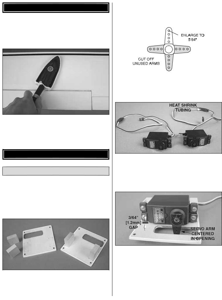
2. Cut three arms from a four-armed servo arm for the aileron servo. Enlarge the outer hole of the remaining arm with a 5/64" [2mm] drill bit.
3. Attach a 9" [229mm] servo extension to the aileron servo and secure the connector using tape or heat shrink tubing (not included). Center the servo with your radio system and install the servo arm to the servo perpendicular to the servo case as shown. Be sure to reinstall the servo arm screw into the servo.
4. Position the servo against the underside of the aileron servo hatch cover between the mounting blocks. Shim the aileron servo away from the hatch cover approximately 3/64" [1.2mm] to isolate it from vibration (a business card folded in thirds works well for this). Drill 1/16" [1.6mm] holes through the mounting tabs on the servo case into the blocks. Thread a servo mounting screw (included with the servo) into each hole and back it out. Apply a drop of thin CA to each hole to harden the wood. When the CA has dried, install the servo onto the hatch cover using the hardware supplied with the servo.
8

5. Use the string taped inside the aileron servo bay to pull the servo lead through the wing ribs.
6. Thread a #2 x 3/8" [9.5mm] self-tapping screw into each servo hatch mounting hole in the wing panel and back it out. Apply a drop of thin CA to each hole to harden the wood. Install the aileron hatch cover to the wing panel using four #2 x 3/8" [9.5mm] self-tapping screws and four #2 flat washers.
7. Thread a nylon clevis 20 complete turns onto a 4" [102mm] pushrod. Slide a silicone clevis retainer onto the clevis and connect the clevis to the outer hole of a control horn.
8. Position the control horn over the plywood plate in the aileron (if you cannot see it, hold the aileron at a shallow angle in good lighting or use a small pin to puncture the covering), using the position of the servo arm as a guide. Align the holes in the control horns directly over the aileron hinge line and mark the location of the control horn mounting holes.
9. Drill 1/16" [1.6mm] holes at the marks you made through the plywood plate. Do not drill all the way through the aileron! Thread a #2 x 1/2" [13mm] self-tapping screw through each hole and back it out. Apply a couple drops of thin CA glue to each hole to harden the wood. When the glue has dried, install the control horn onto the aileron using two #2 x 1/2" [13mm] self-tapping screws.
9
 Loading...