


GPMA1228
WARRANTY
Great Planes
®
Model Manufacturing Co. guarantees this kit to be free from defects in both material and workmanship at the date of
purchase. This warranty does not cover any component parts damaged by use or modification. In no case shall Great Planes’ liability
exceed the original cost of the purchased kit. Further, Great Planes reserves the right to change or modify this warranty without
notice.
In that Great Planes has no control over the final assembly or material used for final assembly, no liability shall be assumed nor
accepted for any damage resulting from the use by the user of the final user-assembled product. By the act of using the user-
assembled product, the user accepts all resulting liability.
If the buyer is not prepared to accept the liability associated with the use of this product, the buyer is advised to return this
kit immediately in new and unused condition to the place of purchase.
While this kit has been flight tested to exceed normal use, if the plane will be used for extremely high stress flying, such as racing, the
modeler is responsible for taking steps to reinforce the high stress points.
READ THROUGH THIS MANUAL BEFORE
STARTING CONSTRUCTION. IT CONTAINS
IMPORTANT WARNINGS AND INSTRUCTIONS
CONCERNING THE ASSEMBLY AND USE OF
THIS MODEL.
GPMZ0219 for GPMA1228 V1.1© Copyright 2000
P.O. Box 788 Urbana, IL 61803 (217) 398-8970
INSTRUCTION MANUAL
Cessna is a
registered
trademark of
Cessna Aircraft
Company
Wing Span - 62-5/8 in
Wing Area - 577 sq in
Weight - 6 lbs
Wing Loading - 24 oz/sq in
Fuse Length - 47 in
Engine - .40 - .46 2-stroke, .52 4-stroke
Important Safety Precaution......................................................2
Introduction.................................................................................2
Precautions .................................................................................2
Decisions You Must Make..........................................................3
Engine Selection....................................................................3
Preparations................................................................................3
Required Accessories............................................................3
Building Supplies and Tools ..................................................3
Optional Supplies and Tools ..................................................3
General Inspection ................................................................4
Building Notes .......................................................................4
Metric Conversions/Ruler ......................................................4
Parts List................................................................................5
Wing Assembly ...........................................................................6
Wing Installation .........................................................................7
Install the Tail Components .......................................................7
Engine Installation......................................................................9
Landing Gear Installation.........................................................10
Radio Installation ......................................................................11
Aileron Servo Installation.....................................................14
Steering Pushrod Installation...............................................16
Throttle Pushrod Installation................................................17
Fuel Tank Installation ...............................................................17
Cowl Installation .......................................................................19
Window Installation ..................................................................19
Final Assembly..........................................................................20
Radio System Set-Up ...............................................................21
Check the Control Directions...............................................21
Adjust the Control Throws ...................................................21
Route the Receiver Antenna ...............................................22
Balance Your Model..................................................................22
Check the Lateral Balance ..................................................22
Check the Fore–Aft Balance ...............................................22
Preparing to Fly Your Cessna 182 ..........................................23
Charge the Batteries ...........................................................23
Balance the Propeller ..........................................................23
Find a Safe Place to Fly ......................................................23
Ground Check the Model ....................................................23
Range Check Your Radio ....................................................23
Engine Safety Precautions ..................................................24
AMA Safety Code (excerpt)......................................................24
General................................................................................24
Radio Control.......................................................................24
Flying Your Cessna 182 ...........................................................24
Takeoff .................................................................................24
Flying ...................................................................................25
Landing................................................................................25
Engine Mount Template..................................Back Cover Page
Cowl Opening Template .................................Back Cover Page
Your Cessna 182 ARF is not a toy, but rather a
sophisticated, working model that functions very much like a
full-size airplane. Because of its realistic performance, the
Cessna 182 ARF, if not assembled and operated correctly,
could possibly cause injury to yourself or spectators and
damage property.
To make your R/C modeling experience totally enjoyable,
we recommend that you get experienced, knowledgeable
help from an instructor with assembly and during your first
flights. You’ll learn faster and avoid risking your model
before you’re truly ready to solo. Your local hobby shop has
information about flying clubs in your area whose
membership includes qualified instructors.
You can also contact the national Academy of Model
Aeronautics (AMA), which has more than 2,500 chartered
clubs across the country. Through any one of them,
instructor training programs and insured newcomer training
are available. Contact the AMA at the address or toll-free
phone number below:
Academy of Model Aeronautics
5151 East Memorial Drive
Muncie, IN 47302-9252
Tele. (800) 435-9262
Fax (765) 741-0057
Or via the Internet at: http://www.modelaircraft.org
The Great Planes Cessna 182 ARF is a high performance
sport airplane that closely resembles the full-size Cessna
182 both in appearance and performance. The Cessna 182
ARF is very stable and predictable, allowing even low time
pilots to enjoy it.
This is not a beginner’s airplane! While the Cessna 182
ARF is easy to build and flies great, we must discourage you
from selecting this kit as your first R/C airplane. It lacks the
self-recovery characteristics of good basic trainers such as
the Great Planes PT
™
Series. On the other hand, if you have
already learned the basics of R/C flying, and you are able to
safely handle a .40-size scale airplane, the Cessna 182
ARF is an excellent choice to try your skills at flying a sport
scale airplane.
1. You must assemble the model according to the
instructions. Do not alter or modify the model, as doing so
may result in an unsafe or unflyable model. In a few cases
the instructions may differ slightly from the photos. In those
instances the written instructions should be considered as
correct.
2. Take time to build straight, true and strong.
3. Use an R/C radio system that is in first-class condition,
and a correctly sized engine and components (fuel tank,
wheels, etc.) throughout your building process.
4. You must properly install the R/C radio system and other
components so that the model operates properly on the
ground and in the air.
PRECAUTIONS
INTRODUCTION
PROTECT YOUR MODEL, YOURSELF
& OTHERS...FOLLOW THIS
IMPORTANT SAFETY PRECAUTION
TABLE OF CONTENTS
2
5. You must test the operation of the model before every
flight to insure that all equipment is operating and you must
make certain that the model has remained structurally
sound. Be sure to check clevises or other connectors often
and replace them if they show signs of wear or fatigue.
Remember: Take your time and follow directions to end
up with a well-built model that is straight and true.
Please inspect all parts carefully before starting to
build!
YOU CAN CONTACT US...
If any parts are missing, broken or defective, or if you
have any questions about building or flying this
airplane, please call us at (217) 398-8970. You can also
check our web site at www.greatplanes.com for the
latest
Cessna 182 ARF
updates, or e-mail your questions to:
productsupport@greatplanes.com
If you are calling for replacement parts, please
reference the part numbers and have them ready when
calling.
Items in parentheses such as (GPMQ4243) are suggested
part numbers recognized by distributors and hobby shops
and are listed for your ordering convenience. GPM is the
Great Planes brand, TOP is the Top Flite
®
brand, and HCA
is the Hobbico
®
brand.
❏ Four-channel Radio With Five Servos
❏ Engine - See Engine Selection Above
❏ Propeller (Top Flite
®
Power Point
®
–Refer To Your
Engine’s Instructions For Proper Size)
❏ Medium Fuel Tubing (GPMQ4131)
❏ 6" Servo Extension (2)
❏ “Y” connector (1)
These are the building tools that are required. We
recommend Great Planes Pro
™
CA and Epoxy glue.
❏ 2 oz. Pro CA (Thin, GPMR6003)
❏ 2 oz. Pro CA+ (Medium, GPMR6009)
❏ 6-Minute Pro Epoxy (GPMR6045)
❏ 30-Minute Pro Epoxy (GPMR6047)
❏ Epoxy Brushes (GPMR8060)
❏ Pro Thread Locking Compound (GPMR6060)
❏ T-pins (HCAR5150)
❏ Adjustable Wrench
❏ Plastic Wrap or Waxed Paper
❏ Isopropyl Alcohol (70%)
❏ Mixing Sticks (GPMR8055)
❏ Round Toothpicks
❏ Hobby Knife (TOWR1010), #11 Blades (TOWR1015)
❏ Small Hobby Clamps
❏ String
❏ Builders Triangle Set (HCAR0480)
❏ Masking Tape (TOPR8018)
❏ Sandpaper (coarse, medium, fine grit)
❏ Easy-Touch
™
Bar Sander (GPMR6170, or similar)
❏ 1/4" Latex Foam Rubber Padding (HCAQ1000)
❏ Paper Towels
❏ Felt-Tip Marker
❏ Wire Cutter
❏ Pliers
❏ Long Nose Pliers
❏ File
❏ Drill Bits: 1/16" [1.5mm], 5/64" [2mm], 3/32" [2.5mm],
1/8" [3mm], 5/32" [4mm], 3/16" [5mm], 1/4" [6mm],
1/2" [13mm]
❏ R/C-56 Canopy Glue
❏ CA Applicator Tips (HCAR3780)
❏ CA Debonder (GPMR6039)
❏ Sealing Iron (TOPR2100)
❏ Heat Gun (TOPR2000)
❏ Single-edge Razor Blades (HCAR0312)
❏ Curved Tip Canopy Scissors for Trimming Plastic
Parts (HCAR0667)
❏ Switch and Charge Jack (GPMM1000)
❏ Center Punch
❏ Hook and Loop Material (GPMQ4480)
❏ Dead Center
™
Engine Mount Hole Locator
(GPMR8130)
❏ Fuel Filler Valve (GPMQ4160)
Optional Supplies & Tools
Building Supplies & Tools
Required Accessories
PREPARATIONS
Engine Selection
There are several engines that will work well in your
Cessna 182 ARF. We recommend a 2-stroke such as an
O.S.
®
.40 LA, O.S. .40 FX, O.S. .46 FX, or the
SuperTigre
®
GS-40 or GS-45. For unsurpassed power
and realistic sound, an O.S. FS-52 4-stroke can’t be beat.
DECISIONS YOU MUST MAKE
Note: We, as the kit manufacturer, provide you with a
top quality kit and great instructions, but ultimately
the quality of your finished model depends on how
you build it; therefore, we cannot in any way
guarantee the performance of your completed model,
and no representations are expressed or implied as to
the performance or safety of your completed model.
3
Remove the fuselage, wing panels, rudder assembly and
stabilizer assembly from their bags. Inspect all items closely
to check for any damage. If any of the control surfaces are
attached, simply pull them apart and store the hinges in a
safe place until it is time to re-attach them. The manual
begins with all the surfaces shown separated.
Your Cessna 182 is covered with high quality Top Flite
MonoKote
®
covering. If any of the covering has loosened,
use a heat gun or sealing iron to correct any of these
problems.
Several times during construction we refer to the “top” or
“bottom” of the model or a part of the model. It is understood
that the “top” or “bottom” of the model is as it would be when
the airplane is right side up and will be referred to as the
“top” even if the model is being worked on upside-down.
Building NotesGeneral Inspection
4
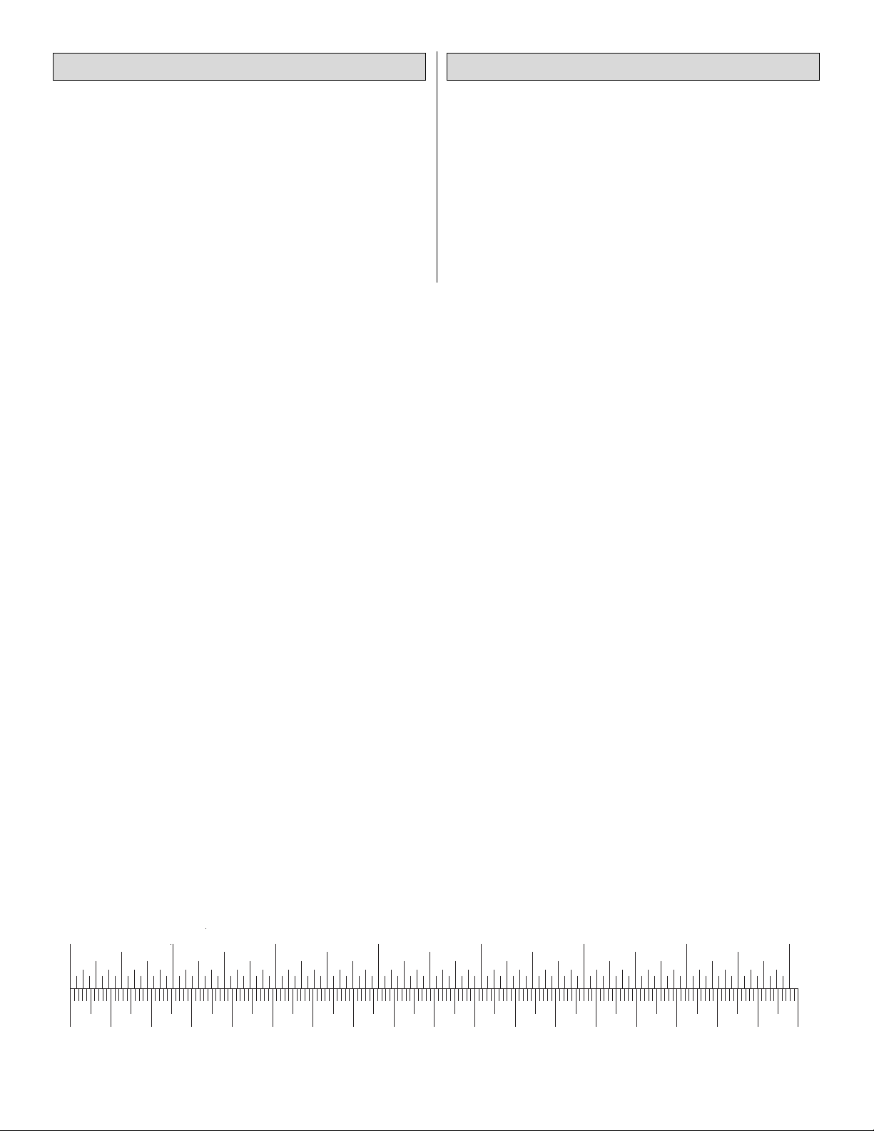
0" 1" 2" 3" 4" 5" 6" 7"
0 10 20 30 40 50 60 70 80 90 100 110 120 130 140 150 160 170 180
Inch Scale
Metric Scale
1/64" = .4mm
1/32" = .8mm
1/16" = 1.6mm
3/32" = 2.4mm
1/8" = 3.2mm
5/32" = 4mm
3/16" = 4.8mm
1/4" = 6.4mm
3/8" = 9.5mm
1/2" = 12.7mm
5/8" = 15.9mm
3/4" = 19mm
1" = 25.4mm
2" = 50.8mm
3" = 76.2mm
6" = 152.4mm
12" = 304.8mm
15" = 381mm
18" = 457.2mm
21" = 533.4mm
24" = 609.6mm
30" = 762mm
36" = 914.4mm
Metric Conversions
5
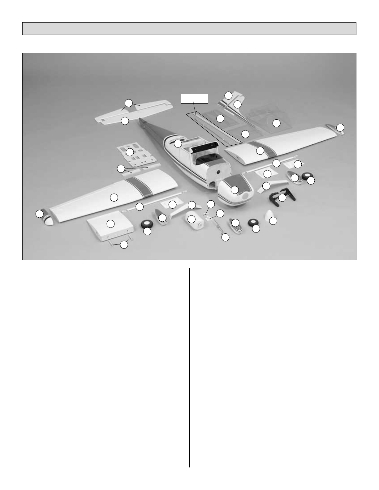
Key# Description Qty
1 Fuselage 1
2 Left Wing Panel w/Aileron 1
3 Right Wing Panel w/Aileron 1
4 Left Wing Tip 1
5 Right Wing Tip 1
6 Wing Strut (Left & Right) 2
7 Left Wheel Pant 1
8 Right Wheel Pant 1
9 Nose Gear Wheel Pant 2
10 Aluminum Landing Gear (Right & Left) 2
11 Stabilizer 1
12 Elevator Assembly (Right & Left) 2
13 Rudder 1
14 Vertical Fin 1
15 Wing Center-Section 1
16 Wing Dowels 2
17 Wing Strut Fairing (Left & Right) 2
18 Landing Gear Fairing 1
19 Main Wheels 2
20 Nose Wheel 1
21 Fuel Tank 1
22 Steering Arm 1
23 Nose Gear Mount 1
24 Nose Gear 1
25 Spinner 1
26 Adjustable Engine Mount
(Left & Right Halves) 2
27 Side Windows (Left & Right) 2
28 Rear Window 1
29 Front Window 1
30 Cowl 1
31 Servo Tray 1
32 Wing Joiners 2
Parts Not Shown In Photo
Description Qty
CA Hinge Strip (2" x 9") 1
Hardware Bag 1
Replacement Parts
If needed, replacement parts for your
Cessna 182 ARF
are
available through your hobby supplier.
Wing Kit..................................................................GPMA2070
Fuselage Kit ...........................................................GPMA2071
Tail Set ...................................................................GPMA2072
Cowl .......................................................................GPMA2073
Windows.................................................................GPMA2074
Landing Gear Set ...................................................GPMA2075
Wheel Pants...........................................................GPMA2076
Strut Set .................................................................GPMA2077
Wing Tips................................................................GPMA2078
Parts List
11
27
Pushrods
29
28
13
21
2
3
1
30
9
7
31
6
8
19
19
15
20
17
18
17
25
24
6
4
5
10
10
16
14
32
12
23
26
22
❏ 1. Mark the ailerons left and right and remove them from
the wing panels. Remove the covering from the aileron
servo openings on the bottom of the wing only. Cut 1/8"
[3mm] inside of the opening to allow some material to be
ironed down inside the opening. Use a sealing iron to secure
the covering around the openings.
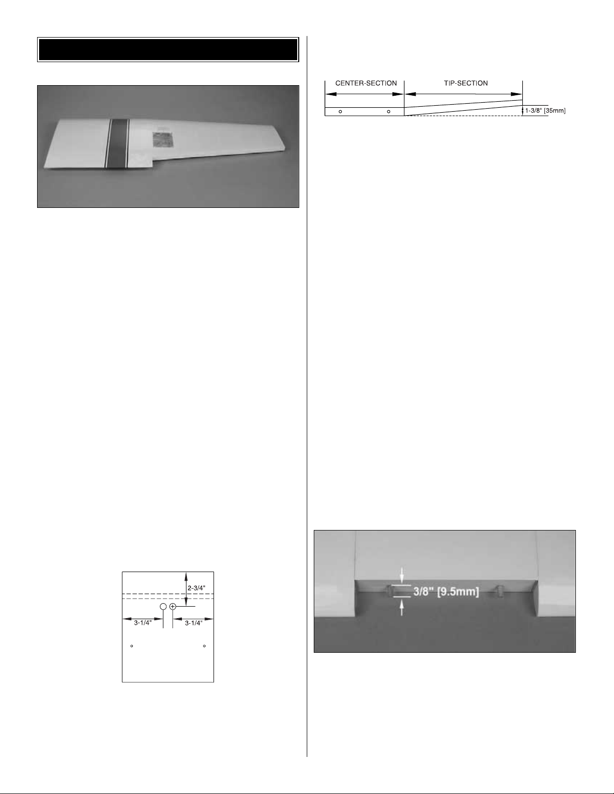
❏ 2. Locate the pre-installed strings in the wing center-
section and wing outer panels. When attaching the wing
outer panels to the wing center-section, the strings for
installing the aileron servos must be moved so they do not
interfere with the fit of the panels. Don’t remove the string
because you will use it to pull your aileron servo cords
through the wing later. Tape each of the strings located in
the aileron servo openings in the outer tip panels to the
bottom of the wing.
❏ 3. Locate the hardwood wing joiners. Test fit the wing
joiner into the right wing panel and the right side of the wing
center-section. The joiner is positioned so 1/3 is in the wing
center-section, and 2/3 is in the tip panel. A snug fit of the
joiner is desirable. If the joiner does not fit properly, lightly
sand any uneven surfaces of the joiner edges and sides.
Repeat this step to check the fit of the other wing joiner in
the left wing panel. Label each wing joiner for orientation
and the side that it is to be used on.
❏ 4. Drill two 1/2" [13mm] holes in the BOTTOM of the wing
center-section as shown in the drawing. The servo leads will
exit from these holes. The holes are located 2-3/4" [70mm]
back from the front of the wing center-section and 3-1/4"
[83mm] from the edges.
Make a dry run of the following step without using any glue
so you will know how to join your wing together, then
proceed using glue.
❏ 5. Un-tape the pre-installed strings in the wing center-
section and the right wing outer panel. Tie the strings
together, being careful not to pull the strings out of the
panels. Note: Don’t remove the strings because you will use
them to pull your aileron servo cords through the wing later.
Tape a piece of wax paper or plan protector over your work
surface. Use a liberal amount of 30-minute epoxy to glue the
wing joiner into the right wing panel and wing center-section.
Apply epoxy to all sides of the joiner, joiner pockets, and
center ribs of both the right wing panel and wing center-
section. Join the wing panel and wing center-section. Use
masking tape to tightly tape the right wing panel and wing
center-section together. Be certain the leading and trailing
edges align. If you have used enough epoxy, it will “ooze”
out from the joint between the two ribs. Wipe off any excess
epoxy from the outside of the wing with a paper towel and
rubbing alcohol. With the wing center-section upright and
flat on your building surface, measure the distance from
your work surface to the tip of the wing outer panel to make
sure you have the correct amount of dihedral as shown in
the sketch. After the epoxy has cured, repeat this step to join
the left wing panel to the wing center-section.
❏ 6. Locate the two 1/4" x 2-1/8" [6mm x 54mm] hardwood
wing dowels. Slightly bevel the ends of the dowels. Test fit
the dowels into the wing, making sure they lock into the
holes inside the wing. If necessary, clean out the holes in the
wing using a 1/4" [6mm] drill bit. Use 30-minute epoxy to
glue the dowels into the wing, letting them protrude
3/8" [9.5mm]. Wipe off any excess epoxy using a paper
towel and rubbing alcohol.
WING ASSEMBLY
6
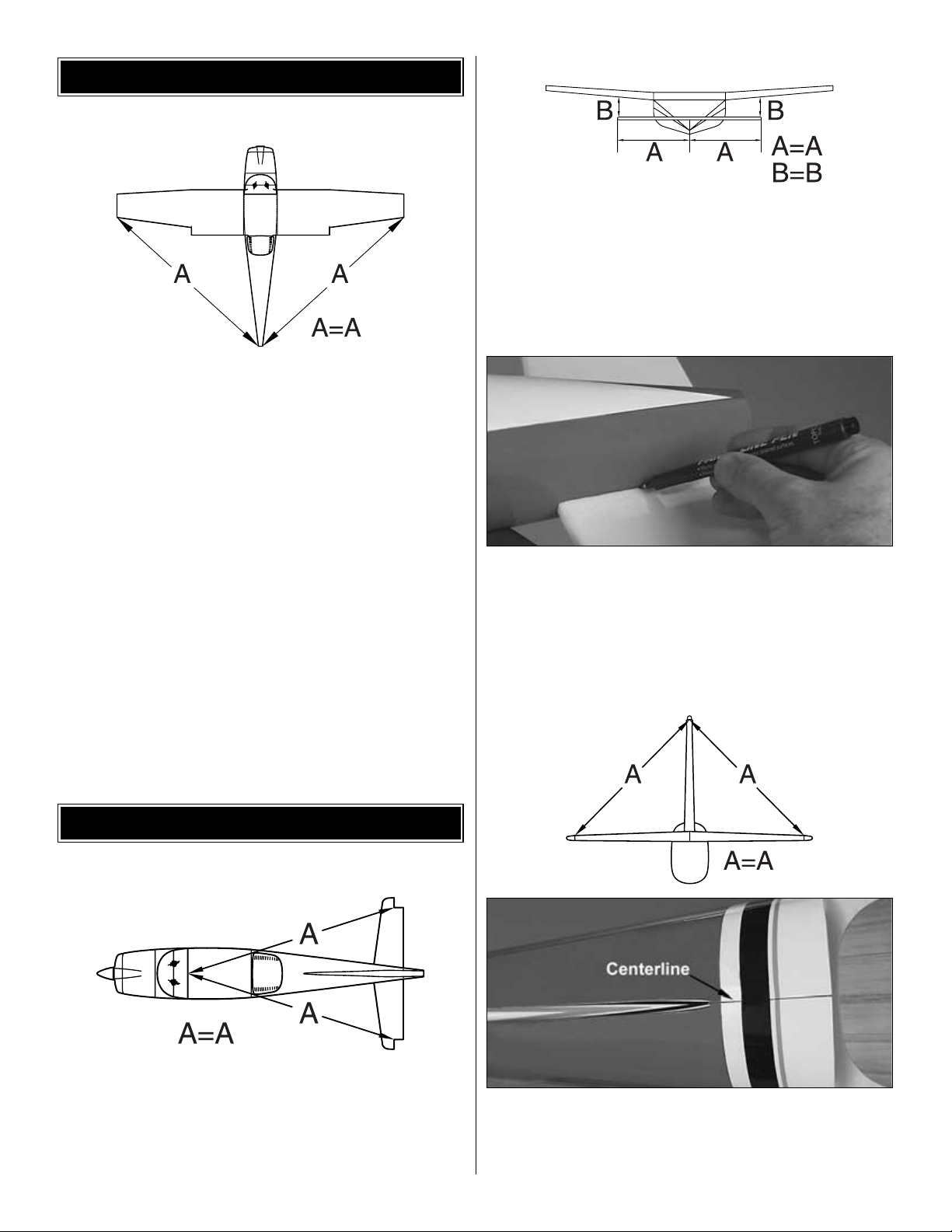
❏ 1. After the epoxy has cured from the previous step,
place
the wing on the fuselage. Measure from the aft center of the
fuselage to one wing tip and record the distance. Measure
from the same point to the opposite wing tip, and compare it
to the first measurement. If the measurements are not the
same, adjust the wing and re-measure until they are equal.
Place a mark on the wing and fuselage so it can be
repositioned accurately for the following steps.
❏ 2. Remove the covering from the wing center-section
where the wing bolts will pass through the wing.
❏ 3. Bolt the wing to the fuselage using two 6-32 x 1-1/4"
machine screws and two 6-32 washers. Check the
alignment
of the wing and enlarge the holes in the wing slightly to allow
the wing to be shifted to match the alignment marks.
❏ 1. Remove the covering from the slot in the fuselage for the
horizontal stabilizer. The location for the stabilizer can be
located by gently pressing the covering using your index
finger along the sides of the fuselage. Slide the stabilizer
into
position, and check the alignment as shown in the sketch.
❏ 2. Mount the wing to the fuselage using the bolts. Stand
back 8 to 10 feet [2.5 to 3 meters] and view the model from
the front and rear. The stabilizer tips should be equally
spaced above the level of the wing. If not, lightly sand the
high side of the stab saddle to correct the problem. Work
slowly and check the alignment often.
❏ 3. When the alignment is correct, mark the outline of the
fuselage onto the bottom and top of the stabilizer. Remove
the stabilizer, and trim the covering 1/32" [.8mm] inside of
the lines, being careful not to cut into the underlying wood.
Slide the stabilizer back into the fuselage, re-check the
alignment, and wick thin CA along the joint between the
stabilizer and fuselage.
❏ 4. Remove the covering on the fuselage under the
vertical fin. Draw a centerline on the top of the fuselage for
use in aligning the fin. Slide the fin into position, and check
the alignment as shown in the sketch and photo. Draw a line
INSTALL THE TAIL COMPONENTS
WING INSTALLATION
7
along both the sides of the fin where it meets the fuselage
and remove the covering 1/32" [.8mm] inside the line, being
careful not to cut into the underlying wood. Sand the bottom
of the fin and the slot in the fuselage if the fin is out of
alignment. Do not force the forward section of the fin into
position, as this will result in poor flight characteristics. Use
30-minute epoxy to glue the fin in position. Work the epoxy
into the slot in the fuselage, filling any loose-fitting joints
between the fuselage and stabilizer. Check the alignment of
the fin to the stabilizer with a triangle, then secure it in
position with masking tape until the epoxy has cured.
Double-check the alignment of the fin with the stabilizer
while the epoxy cures.
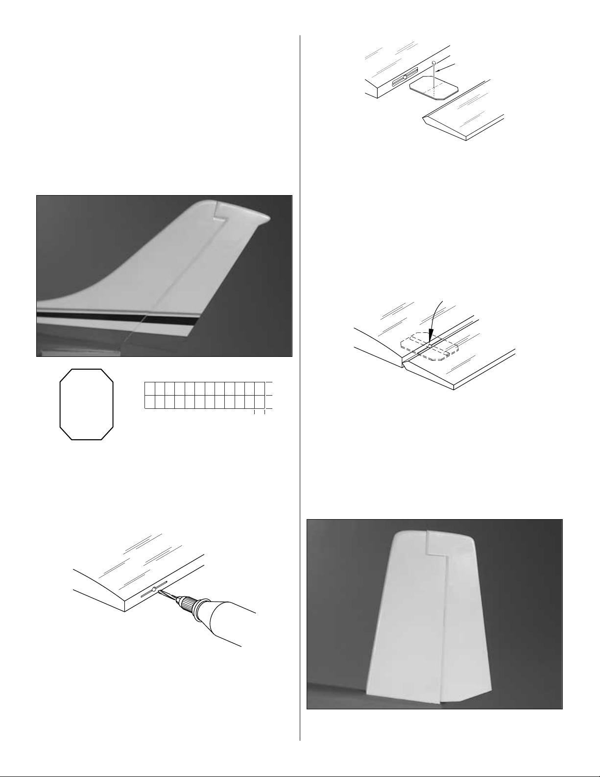
❏ 5. Test fit the rudder to the fin with the hinges. If the
hinges are difficult to install or don’t go in far enough,
carefully enlarge the hinge slots with a hobby knife and a
#11 blade. (Cut the hinges to the size shown above from the
2" x 9" [51mm x 229mm] hinge material.) Use the following
procedure for gluing the hinges and tail gear assembly:
❏ A. Drill a 3/32" [2.5mm] hole, 1/2" [13mm] deep, in the
center of the hinge slot. If you use a Dremel
®
MultiPro
™
for
this task, it will result in a cleaner hole than if you use a
slower speed drill. Drilling the hole will twist some of the
wood fibers into the slot, making it difficult to insert the
hinge, so you should reinsert the knife blade, working it back
and forth a few times to clean out the slot.
❏ B. If the hinges don’t remain centered, remove the rudder
and insert a pin in the center of the hinges. Make sure there
is approximately a 1/64" [.4mm] gap between the rudder and
the fin.
❏ C. Add six drops of thin CA to the center of the hinges on
both sides. Use a paper towel to absorb excess CA from the
hinge gap before it cures. Do not use CA accelerator; allow
the CA to cure slowly.
❏ 6. Use the same hinging method to join the Elevators to
the stab.
ASSEMBLE, THEN APPLY 6 DROPS
OF THIN CA TO CENTER
OF HINGE, ON BOTH SIDES
TEMPORARY PIN
TO KEEP HINGE
CENTERED
DRILL A 3/32" [2.5mm] HOLE
1/2" [13mm] DEEP, IN CENTER
OF HINGE SLOT
1"
[25mm]
1"
[25mm]
3/4"
[19mm]
8
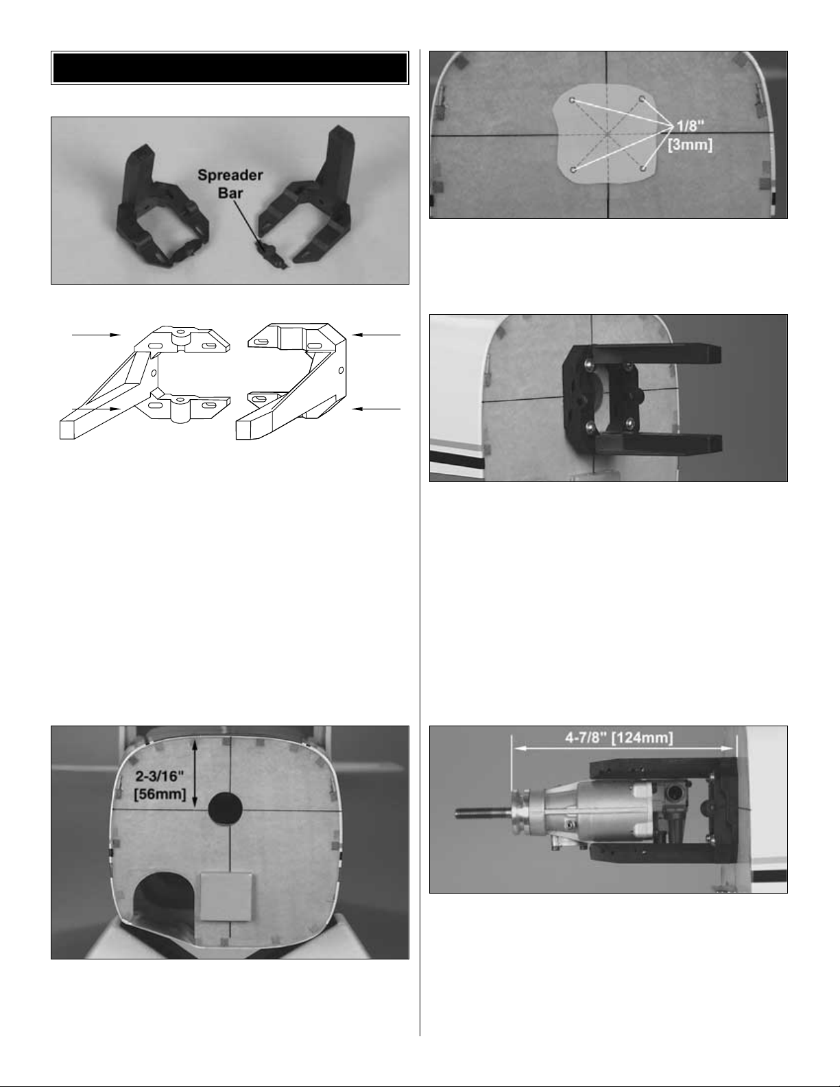
❏ 1. Cut or break the “spreader bar” from each engine
mount
half. Carefully trim any extra material left by the spreader
bar from each mount half. The surfaces where the spreader
bars were attached must be smooth to allow the mount
halves to fit together. Trim the flashing off any rough edges
if necessary.
❏ 2. Draw a horizontal line on the firewall 2-3/16" [56mm]
from the top of the fuselage. Draw a vertical line on the
firewall along the left side of the top and bottom stringers as
shown in the photo.
❏ 3. Cut the engine mount template from the back cover
page and tape it to the firewall as shown above. At the
locations on the template, drill four 1/8" [3mm] holes in the
firewall for the engine mount blind nuts.
❏ 4. Install four 4-40 blind nuts to the inside of the firewall.
Pull the blind nuts into the back side of the firewall using a
4-40 machine screw (with a flat washer under the head of
the bolt). Fit the two halves of the engine mount together.
Use four #4 flat washers and four 4-40 x 3/4" machine
screws to secure the engine mount to the firewall. Do not
tighten the screws at this time, as the mount must be
adjusted for the engine.
❏ 5. Test fit your engine into the mount. Adjust the width of
the rails to fit the engine snugly. Tighten the mount screws
to allow marking the engine mounting holes without moving
the rails.
❏ 6. Position the engine on the engine mount rails so the
propeller thrust washer (or spinner backplate) is 4-7/8"
[124mm] ahead of the firewall. Use a Great Planes Dead
Center Hole Locator (GPMR8130) (not included) or a
sharpened piece of wire to scribe the four engine mount
holes onto the rails. Use a center punch on the marks to
prevent the drill bit from wandering, then drill 3/32" [2.5mm]
pilot holes through the rails. Be sure to hold the drill
ENGINE INSTALLATION
9
 Loading...