


A. R. F.
Almost Ready to Fly
INSTRUCTION MANUAL
WARRANTY
Great Planes® Model Manufacturing Co. guarantees this kit to be free from defects in both material and workmanship at the date of purchase. This warranty does not cover any component parts damaged by use or modification. In no case shall Great Planes’ liability exceed the original cost of the purchased kit. Further, Great Planes reserves the right to change or modify this warranty without notice.
In that Great Planes has no control over the final assembly or material used for final assembly, no liability shall be assumed nor accepted for any damage resulting from the use by the user of the final user-assembled product. By the act of using the userassembled product, the user accepts all resulting liability.
If the buyer is not prepared to accept the liability associated with the use of this product, the buyer is advised to return this kit immediately in new and unused condition to the place of purchase.
While this kit has been flight tested to exceed normal use, if the plane will be used for extremely high stress flying, such as racing, the modeler is responsible for taking steps to reinforce the high stress points.
READ THROUGH THIS MANUAL BEFORE STARTING CONSTRUCTION. IT CONTAINS IMPORTANT WARNINGS AND INSTRUCTIONS CONCERNING THE ASSEMBLY AND USE OF THIS MODEL.
P.O. Box 788 |
Urbana, IL 61803 (217) 398-8970 |
© Copyright 2000 |
GPMZ0227 for GPMA1225/1226 V1.0 |
TABLE OF CONTENTS |
|
Important Safety Precautions ......................................... |
2 |
Introduction ...................................................................... |
2 |
Precautions....................................................................... |
2 |
Decisions You Must Make ............................................... |
3 |
Engine Selection.......................................................... |
3 |
Preparations...................................................................... |
3 |
Required Accessories .................................................. |
3 |
Building Supplies and Tools......................................... |
3 |
Optional Supplies Tools ............................................... |
3 |
General Inspection....................................................... |
3 |
Building Notes.............................................................. |
3 |
Parts List...................................................................... |
4 |
Metric Conversions ...................................................... |
4 |
Wing Assembly................................................................. |
5 |
Wing Installation............................................................... |
7 |
Install the Tail Components............................................. |
8 |
Engine Installation ......................................................... |
10 |
Prop and Spinner Installation........................................ |
11 |
Mount the Landing Gear................................................ |
11 |
Radio Installation ........................................................... |
13 |
Throttle Pushrod Installation ........................................ |
15 |
Fuel Tank Assembly and Installation ........................... |
15 |
Decal Application ........................................................... |
16 |
Control Throw Adjustment ............................................ |
16 |
Balance Your Model Laterally ....................................... |
16 |
Balance Your Model (CG) .............................................. |
17 |
Preflight........................................................................... |
17 |
Charge the Batteries.................................................. |
17 |
Balance the Propeller ................................................ |
17 |
Find a Safe Place to Fly ............................................ |
17 |
Ground Check the Model........................................... |
17 |
Range Check Your Radio .......................................... |
18 |
Engine Safety Precautions ........................................ |
18 |
AMA Safety Precautions (excerpt) ............................... |
18 |
Flying............................................................................... |
19 |
PROTECT YOUR MODEL, YOURSELF
& OTHERS...FOLLOW THIS
IMPORTANT SAFETY PRECAUTION
Your Big Stik ARF is not a toy, but rather a very sophisticated, working model that functions very much like a full-size airplane. Because of its realistic performance, the Big Stik, if not assembled and operated properly, could possibly cause injury to yourself or spectators and damage property.
To make your R/C modeling experience totally enjoyable, we recommend that you get experienced, knowledgeable help from an instructor with assembly and during your first flights. You'll learn faster and avoid risking your model before you're truly ready to solo. Your local hobby shop has information about flying clubs in your area whose members include qualified instructors.
You can also contact the national Academy of Model Aeronautics (AMA) which has more than 2,500 chartered clubs across the country. Through any one of them, instructor training programs and insured newcomer training are available. Contact the AMA at the address or toll-free phone number below.
Academy of Model Aeronautics
5151 East Memorial Drive
Muncie, IN 47302-9252
Tele. (800) 435-9262
Fax (765) 741-0057
Or via the Internet at: http://www.modelaircraft.org
INTRODUCTION
The Great Planes Big Stik ARF is an aircraft that lets you progress from your trainer aircraft into a model that is not only a good choice for improving your flying skills but is also a great high performance, aerobatic model.
This plane is a good choice for a second airplane or as an aerobatic trainer. We are sure that you will enjoy building and flying the Big Stik ARF.
PRECAUTIONS
1.You must assemble the model according to the instructions. Do not modify or alter the model, as doing so may result in an unsafe or unflyable model. In a few cases the instructions may differ slightly from the photos. In those instances the written instruction should be considered as correct.
2.Take time to build straight, true and strong.
3.Use an R/C radio system that is in first-class condition and a correctly sized engine and components throughout the building process.
4.You must properly install the R/C radio system and other components so that the model operates properly on the ground and in the air.
5.You must test the operation of the model before every flight to insure that all equipment is operating and you must make certain that the model has remained structurally sound. Be sure to check clevises or other connectors often and replace them if they show signs of wear or fatigue.
2
Note: We as the kit manufacturer, provide you with a top quality kit and great instructions, but ultimately the quality of your finished model depends on how you build it; therefore, we cannot in any way guarantee the performance of your completed model, and no representations are expressed or implied as to the performance of your completed model.
Please inspect all parts carefully before starting to build! If any parts are missing, broken or defective, or if you have any questions about building or flying this airplane, please contact us at (217) 398-8970. You can also check our web site at www.greatplanes.com or e-mail your questions to productsupport@greatplanes.com. If you are calling for replacement parts, please have your kit information on hand before calling.
DECISIONS YOU MUST MAKE
Engine Selection
There are several engines that will work well in your Big Stik ARF.
For the .40 Big Stik we recommend a 2-stroke engine such as the O.S.® LA .40, O.S. .40 FX, O.S. .46 FS or the
SuperTigre® G40. For unsurpassed power and realistic sound, an O.S. FS-52 can't be beat.
For the .60 Big Stik we recommend a 2-stroke engine such as the O.S. LA .65, O.S. .61 FX or the SuperTigre G61. If you prefer a four stroke engine the O.S.FS-70 or O.S. FS-91 are both good choices.
PREPARATIONS
Required Accessories
Items in parentheses (GPMQ4243) are suggested part numbers recognized by distributors and hobby shops and are listed for your ordering convenience. GPM is the Great Planes® brand , TOP is the Top Flite® brand, and HCA is the Hobbico® brand.
Four channel radio with five servos
Engine - See Engine Selection above
Propeller (Top Flite® Power Point®–Refer To Your Engine’s Instructions For Proper Size)
6" servo extension (2)
“Y” connector (1) when using a basic 4 channel radio
Building Supplies & Tools
These are the building tools that are required. We recommend Great Planes Pro™ CA and Epoxy glue.
2 oz. Pro CA (Thin, GPMR6003)
2 oz. Pro CA+ (Medium, GPMR6009)
6-Minute Pro Epoxy (GPMR6045)
30-Minute Pro Epoxy (GPMR6047)
Epoxy Brushes (GPMR8060)
Mixing Sticks (GPMR8055)
Hobby Knife (TOWR1010), #11 blades (TOWR1015)
String
Builders Triangle Set (HCAR0480)
Masking Tape (TOPR8018)
1/4" Latex Foam Rubber Padding (HCAQ1000)
Paper Towels
Felt tip pen
Drill Bits: 1/16" (1.5mm), 5/64" (2mm), 3/32" (2.4mm), 5/32" (4mm), 11/64" (4.4mm), 1/8" (3mm), 1/4" (6mm), #8 (5.2mm), #36 (2.8mm)
Optional Supplies & Tools
Sealing Iron (TOPR2100)
Heat Gun (TOPR2000)
Switch and Charge Jack (GPMM1000)
Fuel Filler Valve (GPMQ4160)
General Inspection
Remove the fuselage, wing panels, rudder assembly and stabilizer assembly from their bags. Inspect all items closely to check for any damage.
Your Big Stik ARF is covered with high quality Top Flite MonoKote® covering. If any of the covering has loosened, use a heat gun or sealing iron to tighten it.
Building Notes
During the construction we often refer to the “top” or “bottom” of the model or a part of the model. It is understood that the “top” or “bottom” of the model is as it would be when the airplane is right side up and will be referred to as the “top” even if the model is being worked on upside-down.
3
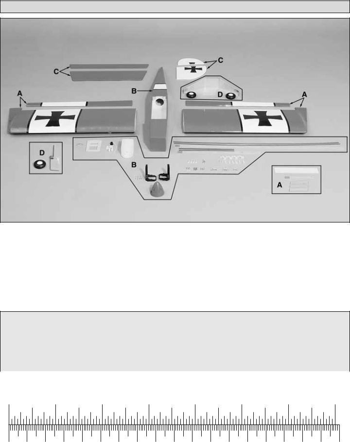
Parts List
Big Stik .40 (GPMA1225) Replacement Parts |
Big Stik .60 (GPMA1226) Replacement Parts |
||
If needed, replacement parts for your Big Stik .40 ARF are |
If needed, replacement parts for your Big Stik .60 ARF are |
||
available through your hobby supplier. |
|
available through your hobby supplier. |
|
Wing Kit (A) ............................................................ |
GPMA2187 |
Wing Kit (A) ............................................................ |
GPMA2191 |
Fuselage Kit (B) ..................................................... |
GPMA2188 |
Fuselage Kit (B) ..................................................... |
GPMA2192 |
Tail Set (C) ............................................................. |
GPMA2189 |
Tail Set (C) ............................................................. |
GPMA2193 |
Landing Gear Set (D)............................................. |
GPMA2190 |
Landing Gear Set (D)............................................. |
GPMA2194 |
|
|
|
|
Metric Conversions
1/64" |
= .4mm |
3/16" |
= 4.8mm |
1" |
= 25.4mm |
18" = 457.2mm |
1/32" |
= .8mm |
1/4" |
= 6.4mm |
2" |
= 50.8mm |
21" = 533.4mm |
1/16" |
= 1.6mm |
3/8" |
= 9.5mm |
3" |
= 76.2mm |
24" = 609.6mm |
3/32" |
= 2.4mm |
1/2" |
= 12.7mm |
6" |
= 152.4mm |
30" = 762mm |
1/8" |
= 3.2mm |
5/8" |
= 15.9mm |
12" |
= 304.8mm |
36" = 914.4mm |
5/32" = 4mm |
|
3/4" = 19mm |
|
15" = 381mm |
|
|
|
Inch Scale |
|
|
|
|
|
|
|
0" |
1" |
2" |
3" |
4" |
5" |
6" |
7" |
0 |
10 |
20 |
30 |
40 |
50 |
60 |
70 |
80 |
90 |
100 |
110 |
120 |
130 |
140 |
150 |
160 |
170 |
180 |
|
Metric Scale |
|
|
|
|
|
|
|
|
|
|
|
|
|
|
|
|
|
4
WING ASSEMBLY
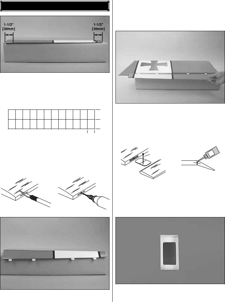
1. Locate the left and right aileron. Make a line 3/4" (19mm) long on the leading edge of the aileron 1-1/2" (38mm) from each end of the aileron. Make two additional 3/4" (19mm) lines, spacing them equally between the first two lines.
1"
1"
3/4"
2. From the 2" x 9" (50mm x 230mm) hinge material, cut out your hinges. A total of 16 hinges will be needed for the entire airplane. The hinges need to be cut to 3/4" x 1" (19mm x 25mm).
to make sure it goes in 1/2" (13mm). The slot can be done with a hobby knife or the Great Planes Slot Machine™. The Slot Machine is a real time saver when cutting slots for hinges. If you are an avid modeler you will find this to be a great tool to add to you shop!
4. Align the aileron in position at the trailing edge of the wing. Be sure to leave at least a 1/6" (1.6mm) spacing between the aileron and the outboard trailing edge of the wing. When you are satisfied with the fit, mark the location for the hinges on the trailing edge of the wing. Do this for the left and right wing.
TEMPORARY PIN |
|
TO KEEP HINGE |
THIN |
|
CA |
CENTERED |
|
CUT HINGE SLOT |
DRILL A 3/32" HOLE |
|
1/2" DEEP, IN CENTER |
||
WITH HOBBY KNIFE |
||
OF HINGE SLOT |
||
AND #11 BLADE |
5. Install the aileron to the wing by applying 6 drops of thin CA to the hinge. After the glue has cured, flex the aileron back and forth a few times to loosen up the hinge. Pull on the aileron to make sure that the aileron is firmly attached to the wing. Repeat this step for the other wing.
3. Cut a 3/4" (19mm) slot in the leading edge of the aileron at the previously marked locations. Trial fit the hinge
6. Locate the servo bay in the bottom of each wing and cut away the MonoKote to reveal the servo tray. Repeat for the other wing.
5
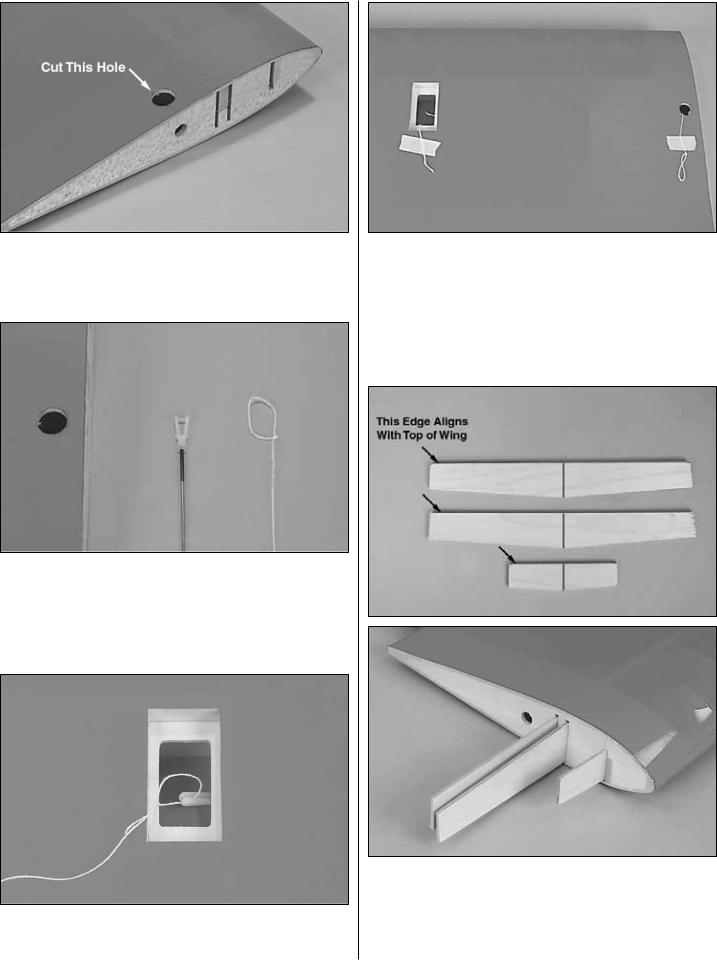
7. On the root rib there is a small hole. This is the hole that the aileron servo wire will be fed through. Directly above this hole make a 1/2” opening through the wing skin. This is easily done with a Dremel® sanding drum.
8. Attach a clevis to one of the included pushrods. Tie a loop onto a piece of string long enough to reach from the servo bay to the hole you made in the wing skin. This string will be used to assist pulling the servo wire through when we get to the installation of the servos.
9. Insert the pushrod through the hole in the root rib until the clevis shows in the servo bay. Put the string onto the clevis and pull the string back through the hole.
10. Pull the string out through the opening in the bottom of the wing skin. Using masking tape, tape the string to the wing at the servo bay and the hole you pulled the string through. Taping the string in place will prevent it from falling back into the wing.
11. Repeat steps 7 - 10 for the other wing.
12. Locate the three wood joiners. Draw a center line on each of them. Trial fit them into both wing halves making sure that the straight edge of the joiner is aligned with the top of the wing. Once you are satisfied with the fit, apply 6-minute epoxy to 1/2 of the joiner and one pocket of one of the wing.
6
 Loading...