


Operator’s/Parts Manual
John Deere 455 25’ & 30’
Flat Fold Marker
Planting Components
Read the operator’s manual entirely. When you see this symbol, the subsequent
!instructions and warnings are serious - follow without exception. Your life and the lives of others depend on it!
13350 |
Cover illustration may show optional equipment not supplied with standard unit.
© Copyright 2002 |
Pr inted 8/8/2002 |
205-046M |

 Table of Contents
General Information . . . . . . . . . . . . . . . . . . . . . . . . .1
Introduction . . . . . . . . . . . . . . . . . . . . . . . . . . . . . . . .2
Using this Manual . . . . . . . . . . . . . . . . . . . . . . . . . . .2
Important Safety Information . . . . . . . . . . . . . . . . . .3
Owner’s Assistance . . . . . . . . . . . . . . . . . . . . . . . . .4
Operating and Assembly Instructions . . . . . . . . . . .5
General Operation & Repair . . . . . . . . . . . . . . . . .5
Installation Instructions . . . . . . . . . . . . . . . . . . . . .6
Hydraulics . . . . . . . . . . . . . . . . . . . . . . . . . . . . . . . .11
Adjusting the Hydraulics . . . . . . . . . . . . . . . . . . .11
Maintenance & Lubrication . . . . . . . . . . . . . . . . . .12
Maintenance . . . . . . . . . . . . . . . . . . . . . . . . . . . .12
Breakaway Protection . . . . . . . . . . . . . . . . . . . . .12
Marker Transporting . . . . . . . . . . . . . . . . . . . . . .12
Lubrication . . . . . . . . . . . . . . . . . . . . . . . . . . . . .13
Troubleshooting. . . . . . . . . . . . . . . . . . . . . . . . . . . .15
Parts . . . . . . . . . . . . . . . . . . . . . . . . . . . . . . . . . . . . .16
Flat Fold Marker Assembly . . . . . . . . . . . . . . . . .16
Disk Assembly. . . . . . . . . . . . . . . . . . . . . . . . . . .20
Hydraulic Assembly. . . . . . . . . . . . . . . . . . . . . . .22
Hydraulic Cylinder . . . . . . . . . . . . . . . . . . . . . . . .24
Sequence Valve . . . . . . . . . . . . . . . . . . . . . . . . .26
Appendix . . . . . . . . . . . . . . . . . . . . . . . . . . . . . . . . .28
Warranty . . . . . . . . . . . . . . . . . . . . . . . . . . . . . . . . . .27
© Copyright 2002 All rights Reserved
Great Plains Manufacturing, Inc. provides this publication “as is” without warranty of any kind, either expressed or implied. While every precaution has been taken in the preparation of this manual, Great Plains Manufacturing, Inc. assumes no responsibility for errors or omissions. Neither is any liability assumed for damages resulting from the use of the information contained herein. Great Plains Manufacturing, Inc. reserves the right to revise and improve its products as it sees fit. This publication describes the state of this product at the time of its publication, and may not reflect the product in the future.
Great Plains Manufacturing, Incorporated Trademarks
The following are trademarks of Great Plains Mfg., Inc.: Application Systems, Ausherman, Land Pride, Great Plains
All other brands and product names are trademarks or registered trademarks of their respective holders.
Printed in the United States of America.
10/17/2002 |
205-046M |

General Information 1
 General Information
Important Notice
Great Plains Manufacturing, Inc. provides this publication “as is” without warranty of any kind, either expressed or implied, while every precaution has been taken in the preparation of this manual, Great Plains Manufacturing, Inc. assumes no responsibility for errors or omissions. Neither is any liability assumed for damages resulting from the use of the information contained herein. Great Plains Manufacturing, Inc. reserves the right to revise and improve its products as it sees fit. This publication describes the state of this product at the time of its publication, and may not reflect the product at all times in the future.
Printed in the United States of America.
For your convenience, record your Model and the Date Purchased on page 4. Have this information before you when calling a Great Plains Authorized Dealer.
This Operator’s Manual applies to the
Product Name listed below:
Flat Fold Marker for John Deere 455 25’ & 30’
10/17/2002 |
205-046M |

2 John Deere 455 25’ & 30’
 Introduction
Great Plains welcomes you to its growing family of new product owners. This Flat Fold Marker has been designed with care and built by skilled workers using quality materials. Proper setup, maintenance and safe operating practices will help you get years of satisfactory use from the machine.
Description of Unit
The parts on your Flat Fold Marker have been specially designed and should only be replaced with genuine Great Plains parts. Therefore, should your Flat Fold Marker require replacement parts go to your Great Plains Dealer.
Using This Manual
This manual will familiarize you with safety, assembly, operation, adjustments and maintenance. Read this manual and follow the recommendations to help ensure safe and efficient operation.
The information in this manual is current at printing. Some parts may change to assure top performance.
Definitions
The following terms are used throughout this manual.
Right-hand and left-hand as used in this manual are determined by facing the direction the machine will travel while in use unless otherwise stated.
IMPORTANT: A crucial point of information related to the preceding topic. For safe and correct operation, read and follow the directions provided before continuing.
NOTE: Useful information related to the preceding topic.
205-046M |
10/17/2002 |

Important Safety Information 3
 Important Safety Information
Look for Safety Symbol
The SAFETY ALERT SYMBOL indicates there is a potential hazard to personal safety involved and extra safety precaution must be taken. When you see this symbol, be alert and carefully read the message that follows it. In addition to design and configuration of equipment, hazard control and accident prevention are dependent upon the awareness, concern, prudence and proper training of personnel involved in the operation, transport, maintenance and storage of equipment.
Be Aware of Signal Words
Signal words designate a degree or level of hazard seriousness.
DANGER indicates an imminently hazardous situation which, if not avoided, will result in death or serious injury. This signal word is limited to the most extreme situations, typically for machine components that, for functional purposes, cannot be guarded.
WARNING indicates a potentially hazardous situation which, if not avoided, could result in death or serious injury, and includes hazards that are exposed when guards are removed. It may also be used to alert against unsafe practices.
CAUTION indicates a potentially hazardous situation which, if not avoided, may result in minor or moderate injury. It may also be used to alert against unsafe practices.
!
!DANGER
!WARNING
!CAUTION
10/17/2002 |
205-046M |

4 John Deere 455 25’ & 30’
Owner Assistance
If you need customer service or repair parts, contact a Great Plains dealer. They have trained personnel, repair parts and equipment specially designed for Great Plains products.
Your machine’s parts were specially designed and should only be replaced with Great Plains parts. Always use the model number when ordering parts from your Great Plains dealer.
Record your Model and Date Purchased here for quick reference:
Model:________________________________
Date Purchased:_________________________
Your Great Plains dealer wants you to be satisfied with your new machine. If you do not understand any part of this manual or are not satisfied with the service received, please take the following actions.
1.Discuss the matter with your dealership service manager. Make sure they are aware of any problems so they can assist you.
2.If you are still unsatisfied, seek out the owner or general manager of the dealership.
3.For further assistance write to:
Product Support
Great Plains Mfg. Inc., Service Department
PO Box 5060
Salina, KS 67402-5060
205-046M |
10/17/2002 |

Operating and Assembly Instructions 5
 Operating and Assembly Instructions
Most accidents are the result of negligence and carelessness, usually caused by failure of the operator to follow simple but necessary safety precautions. The following safety precautions are suggested to help prevent such accidents. The safe operation of any machinery is a big concern to consumers and manufactures.Your Flat Fold Marker has been designed with many built-in safety features. However, no one should operate this product before carefully reading this Operators Manual.
General Operation & Repair
Never allow the Flat Fold Marker to be operated by anyone who is unfamiliar with the operation of all functions of the unit. All operators should read and thoroughly understand the instructions given in this manual prior to moving the unit.
1.Make sure safety rules are understood before operating machinery or tractor.
2.Never permit any persons other than the operator to ride on the tractor.
3.Never permit any persons to ride on or stand near the drill while it is in operation.
4.Regulate your speed to the field conditions, maintaining complete control at all times.
5.After repairing or adjusting, make sure all tools and parts are removed from the implement before attempting to operate it.
6.Do not grease or oil machine while it is in operation.
7.Loose fitting clothing should not be worn as it may catch in moving parts.
8.Never dismount from a moving tractor.
9.Do not leave the tractor or the implement unattended with the engine running.
10.Do not stand between the tractor and the implement during hitching.
11.Detach and store implements in an area where children normally do not play. Stabilize implements by using suitable supports and block wheels.
10/17/2002 |
205-046M |
6 John Deere 455 25’ & 30’
12.If a hydraulic leak develops, correct it immediately. Escaping hydraulic oil can have extremely high pressure. A stream of high pressure oil may easily penetrate the skin as with modern needle-less vaccination equipment - but with the exception that hydraulic fluid may cause blood poisoning. It is imperative that the connections are tight and that all lines and pipes are in good condition. If an injury is caused by the escaping hydraulic fluid, see doctor at once!
13.Use a piece of cardboard or wood to detect leaks of hydraulic oil under pressure.
14.Be sure to relieve all hydraulic pressure before disconnecting any lines or pipes between the implement and the tractor hydraulic system.
Keep all guards and shields in place.
John Deere 455 Marker
Installation Instructions
See the “Parts Section” of this manual to identify individual components not mentioned in these installation instructions.
1. Place drill in a lowered field position. From each end of the drill box allow 16 ft. clearance for marker assembly.
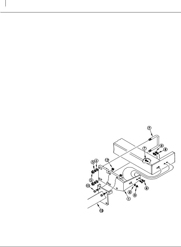
Refer to Figure 1
2. Mount the adapter plate (1) to the John Deere 455 Drill using u-bolt (2), USS flat washers (4), hardened flat washers (3), and lock flange nut (5). Also use 2- 1/2” x 1 1/2” bolts (6) and 1-1/2” x 1 1/4” carriage bolt (7) with flat washers (8), and locking flange nuts (9). The carriage bolt (7) is inserted into the holes with the slots head first. It is then slid sideways into the square slot to be tightened
3. Attach the marker first section with mount (10) to the adapter plate on the drill frame as illustrated. Mount the 5/8” x 2" long bolts (11), and flanged hex nuts (12).
Figure 1 |
13391 |
Adapter Plate
205-046M |
10/17/2002 |
Operating and Assembly Instructions 7
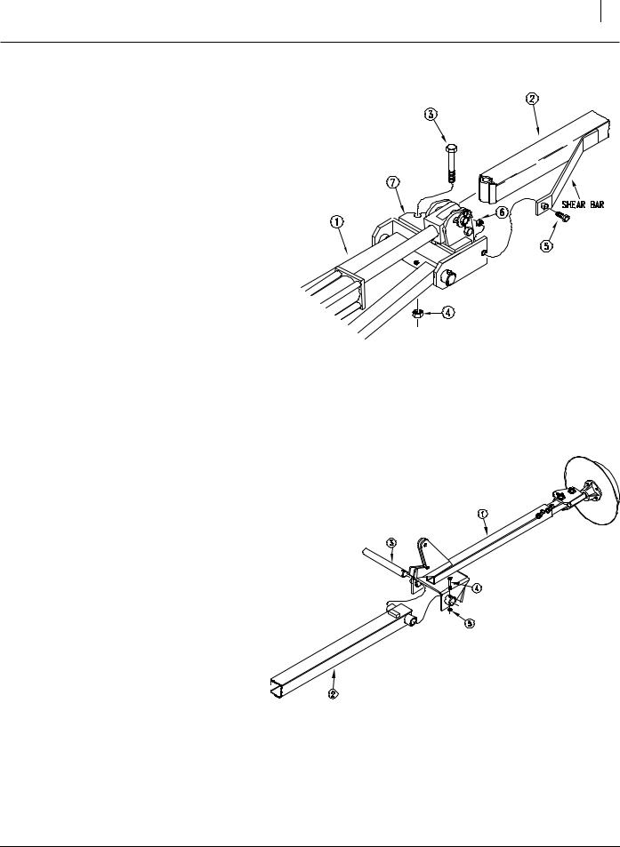
Refer to Figure 2
4. Assemble the marker in a horizontal position, remove the port plugs in the hydraulic cylinder to allow the fold cylinder to be extended. Then fold the first section and the lift lug channel (7) to a horizontal position.
5. With the shear bar positioned towards the front (2), align the holes of the second section with the holes of the lift lug channel (7) and bolt together with the 5/8” x 5 1/2” long bolt (3), lock nut (4), 3/8” x 2" long shear bolt (5), and lock nut (6).
Figure 2 |
13392 |
Lift Lug Channel and Shear Bar
Refer to Figure 3
6.Place the third section (1) over the end of the second section (2) and insert hinge pin (3) through the second and third section pivot. Secure the hinge pin (3) with 5/16” x 2" long bolt (4) and lock nut (5).
Figure 3 |
13393 |
Second and Third Sections
10/17/2002 |
205-046M |

8 John Deere 455 25’ & 30’
Refer to Figure 4
7.Bolt the chain bar weldment (1) to the first section (2) with 3/8” x 3 1/4” long bolt (3) and lock nut (4). The chain bar weldment (1) should pivot freely on the 3/8” bolt (3). Bolt the chain bar (5) to the third section (6) with the 3/8” x 1 1/2” long bolt (7) and lock nut (4). The chain bar (5) should pivot freely on the 3/8” bolt (7). Connect the marker chain (10) between the chain bar (5) and chain bar weldment (1) with 5/16” utility clevis (9). With the marker disk adjusted for seeding width and disk touching the ground, adjust chain length to remove the slack. Adjustment should be made at the utility clevis (9) nearest to the drill.
8.The purpose of the 3/8” x 2 1/2” long stop bolt
(11)is to hold tension on the marker chain
(10)ONLY when the marker is in folded position. Therefore; the 3/8” stop bolt (11) and lock nuts (4) should be positioned in the first section (1) so the head of the stop bolt extends as little as possible. After marker is folded, adjust stop bolt to tighten chain.
Refer to Figure 5
9.When mounting the marker carrier arm (1), on the 455, first mount the transport mount arm
(2)to the drill frame using 3/8” x 6" x 7" long u- bolt (3), flat washers (4), and flanged nuts (5). The transport mount arm should be 45" - 55" away from the box end as shown. Next attach the marker carrier arm (1) to the transport mounting arm (2) using the 1/2” x 2" x 3" long u-bolts (6),flat washers (9) and flanged nuts
(7).The marker carrier arm should be set at 31 3/8” - 31 7/8” above the drill frame as shown.
10.Mount the support arm saddle (8) to the marker carrier arm (1) with 1/2” x 2" x 3" long u-bolts (6), flat washer (9), and flanged nuts
(7).The support saddle should be centered under the marker chain and the square tube of the second section, when folded to prevent wear. The support arm should support the second section parallel with the seed box lid. Adjustment can be made by loosening the u- bolts that clamp the marker carrier and slide marker carrier (1) up or down to parallel the marker with the drill box lid.
Figure 4 |
13394 |
Chain Bar Weldment
Figure 5 |
13395 |
Marker Carrier Arm and Transport Carrier Arm
205-046M |
10/17/2002 |
 Loading...