


OPERATOR’S MANUAL
Safety Notices ..................................................................................................... |
1 |
Introduction ......................................................................................................... |
3 |
System Overview .............................................................................................................. |
3 |
Installation and Setup ......................................................................................... |
5 |
Console Mounting ............................................................................................................. |
5 |
Console Harness Installation ............................................................................................ |
6 |
Power Connection ............................................................................................................. |
7 |
Implement Harness/Module Connection ........................................................................... |
9 |
Module Order ................................................................................................................................... |
9 |
Module Installation ........................................................................................................................... |
9 |
Module Setup Examples ................................................................................................................ |
12 |
Connecting Sensors to Modules .................................................................................................... |
14 |
Hopper Level Sensors .................................................................................................................... |
15 |
Harnesses ....................................................................................................................... |
18 |
12 Row Harness ............................................................................................................................. |
18 |
16 Row Harness ............................................................................................................................. |
18 |
Shaft Speed Module Harness ........................................................................................................ |
19 |
RS485 Extension Harness ............................................................................................................. |
19 |
Startup ............................................................................................................... |
21 |
Switchpad Overview ....................................................................................................... |
21 |
On/Off ............................................................................................................................................. |
21 |
Alarm .............................................................................................................................................. |
21 |
Setup .............................................................................................................................................. |
21 |
Min Avg Max Scan ......................................................................................................................... |
21 |
Select Row ...................................................................................................................................... |
21 |
Select .............................................................................................................................................. |
22 |
Set................................................................................................................................................... |
22 |
Start Stop Reset ............................................................................................................................. |
22 |
Back ................................................................................................................................................ |
22 |
Operate 1 ....................................................................................................................................... |
22 |
Operate 2 ....................................................................................................................................... |
23 |
Operate 3 ....................................................................................................................................... |
23 |
Setup Mode ..................................................................................................................... |
24 |
Setup Constants ............................................................................................................................. |
24 |
Seed Flow Alarm Adjustment ......................................................................................................... |
26 |
Population Hi Limit ......................................................................................................................... |
27 |
Population Lo Limit ......................................................................................................................... |
27 |
Row Width ...................................................................................................................................... |
27 |
Implement Width ............................................................................................................................ |
28 |
Ground Speed Source ................................................................................................................... |
28 |
Distance Calibration ....................................................................................................................... |
28 |
Automatic Configuration ................................................................................................................. |
29 |
Split Row Configuration .................................................................................................................. |
30 |
Number of Seed Modules .............................................................................................................. |
31 |
Row Status ..................................................................................................................................... |
32 |
Total Number Of Rows Configured ................................................................................................ |
33 |
Number of Fan Speed Sensors ...................................................................................................... |
33 |
Number of Shaft Speed Sensors ................................................................................................... |
35 |
Seed Manager SE ® |
/I |
11001-1359A-200810

OPERATOR’S MANUAL
Setup Mode Continued ...................................................................................... |
37 |
Number of Hopper Level Sensors .................................................................................................. |
37 |
Number of Pressure Sensors ......................................................................................................... |
38 |
Blockage Mode Configuration ........................................................................................................ |
39 |
Population Filter .............................................................................................................................. |
40 |
Population Scaling Factor ............................................................................................................... |
41 |
Sensor/Module Self-Test ................................................................................................................ |
41 |
English/Metric Units ........................................................................................................................ |
42 |
Customer Setup Constants ............................................................................................................ |
42 |
Operation .......................................................................................................... |
45 |
Operate Mode ................................................................................................................. |
45 |
Run Hours ...................................................................................................................... |
45 |
Population ....................................................................................................................... |
46 |
Population Scan ............................................................................................................. |
46 |
Population Min Avg Max ................................................................................................................. |
47 |
Population Select Row ................................................................................................................... |
47 |
Seed Spacing ................................................................................................................................. |
48 |
Ground Speed ................................................................................................................................ |
48 |
Fan Speed ...................................................................................................................................... |
49 |
Shaft Speed .................................................................................................................................... |
49 |
Pressure ......................................................................................................................................... |
50 |
Area Accumulator ........................................................................................................................... |
50 |
Seed Count ..................................................................................................................................... |
51 |
Distance Accumulator ..................................................................................................................... |
51 |
Speed Area Mode ........................................................................................................................... |
52 |
Alarms ............................................................................................................... |
53 |
All Rows Failed ............................................................................................................................... |
54 |
Rows Failed .................................................................................................................................... |
54 |
Distance Sensor Failed .................................................................................................................. |
54 |
Population Hi Limit Warning ........................................................................................................... |
55 |
Population Lo Limit Warning ........................................................................................................... |
56 |
Fan Speed Hi Limit Warning ........................................................................................................... |
56 |
Fan Speed Lo Limit Warning .......................................................................................................... |
57 |
Shaft Speed Hi Limit Warning ........................................................................................................ |
57 |
Shaft Speed Lo Limit Warning ........................................................................................................ |
58 |
Pressure Hi Limit Warning .............................................................................................................. |
58 |
Pressure Lo Limit Warning ............................................................................................................. |
58 |
Hopper Lo Warning ........................................................................................................................ |
59 |
Battery Voltage Warning ................................................................................................................. |
60 |
Self Test Error Codes ....................................................................................... |
61 |
Connector Pinouts .......................................................................................................... |
65 |
Setup Record Sheet ....................................................................................................... |
66 |
Setup Record Sheet ....................................................................................................... |
67 |
Warranty.............................................................................................................. |
69 |
II / |
Seed Manager SE |
11001-1359A-200810
OPERATOR’S MANUAL
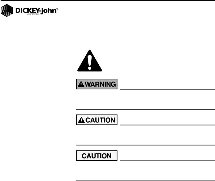
SAFETY NOTICES
Safety notices are one of the primary ways to call attention to potential hazards.
This Safety Alert Symbol identifies important safety messages in this manual. When you see this symbol, carefully read the message that follows. Be alert to the possibility of personal injury or death.
Use of the word WARNING indicates a potentially hazardous situation which, if not avoided, could result in death or serious injury.
Use of the word CAUTION with the Safety Alert Symbol indicates a potentially hazardous situation which, if not avoided, may result in minor or moderate injury.
Use of the word CAUTION without the safety alert symbol indicates a potentially hazardous situation which, if not avoided, may result in equipment damage.
Seed Manager SE® |
SAFETY NOTICES / 1 |
11001-1359A-200810

OPERATOR’S MANUAL
2 / SAFETY NOTICES |
Seed Manager SE |
11001-1359A-200810

OPERATOR’S MANUAL
INTRODUCTION
SYSTEM OVERVIEW
The Seed Manager® SE System monitors up to ninety six (96) seed rows, two (2) fan (RPM) inputs, three (3) shaft speed (RPM) inputs, two (2) pressure inputs, seven (7) hopper level inputs, and (1) ground speed input.
It is compatible with DICKEY-john standard and Hi-Rate seed sensors. Implement configuration data is stored in nonvolatile memory retaining information even when disconnected from the tractor battery.
Figure 1
SeedManager® SE Console
Seed Manager SE® |
INTRODUCTION / 3 |
11001-1359A-200810

OPERATOR’S MANUAL
4 / INTRODUCTION |
Seed Manager SE |
11001-1359A-200810
OPERATOR’S MANUAL
INSTALLATION AND SETUP
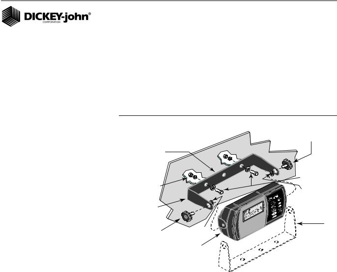
CONSOLE MOUNTING
The console should be mounted inside the tractor cab in a location accessible to the operator but does not obstruct the driving view. (Figure 2) depicts a typical console mount.
Figure 2
Typical Console Mounting using the U-bracket and hardware
Knob
Screw
U-Bracket |
|
|
|
|
1/4-20 x 3/4 Inch |
|
|
Hex Bolts & |
1/4 -20 Nuts |
|
Flat washers |
|
|
|
and Lockwasher |
|
Rubber |
|
|
Washer |
U-Bracket |
|
|
Knob |
Rubber |
U-Bracket |
Washer |
(Preferred Mounting |
|
Screw |
|
Position) |
Console
MOUNTING STEPS
1.Verify the rear side of the selected mounting surface is free of wiring or other obstructions and is accessible for inserting and tightening the mounting bolts.
2.Use the U-shaped mounting bracket as a template to mark the two outside holes of the bracket on the selected location and drill two 9/32 inch holes. An alternate mounting method that allows the console to swivel, requires drilling the center bracket hole only.
3.Attach the mounting bracket to the mounting surface using the ¼ - 20 x ½ inch bolts, lockwashers, flatwashers, and nuts.
4.Secure the console to the mounting bracket using the two knob screws.
5.Insert the two rubber washers between the bracket and console.
6.Tilt console so that the J1 connector on the rear of the console is accessible.
7.Temporarily tighten the two knob screws.
Seed Manager SE |
INSTALLATION AND SETUP / 5 |
11001-1359A-200810

OPERATOR’S MANUAL
CONSOLE HARNESS INSTALLATION
The J1 connector on the back of the console connects all input and output
signals to the Seed Manager® SE console. The primary tractor harness is shown in (Figure 3).
Harness contains connectors for
•Ground speed sensor (digital)
•Ground speed sensor (reluctance)
•System power
•P1 and P2 Bus connectors. A secondary module harness is used to connect to P1 and/or P2.
For systems that contain a J2 connector, a separate accessory harness will contain a RS-232 connector for PC/GPS applications.
Figure 3
Primary Tractor Harness
Note: |
46682-0132 |
Due to the power requirements for the Seed Manager® SE system, the battery connections must be made directly to the tractor battery.
Mates with Reluctance
Ground Speed Sensor
6 / INSTALLATION AND SETUP |
Seed Manager SE |
11001-1359A-200810

OPERATOR’S MANUAL
Note:
Due to the power requirements for the Seed Manager® SE system, the battery connections must be made directly to the tractor battery.
Install the primary (J1) harness from the rear of the console to the tractor hitch as follows:
1.Route the primary harness from J1 on the console rear to the rear of the tractor, near the hitch. Route on the side of the tractor opposite the alternator and spark plugs.
2.Locate the harness to prevent being pinched, cut, or stepped on and secure it with wire ties.
3.Install or connect an existing ground speed sensor. The ground speed sensor may be one of three types – radar, reluctance, or Hall Effect. A radar sensor or reluctance sensor connects directly to the designated connector on the primary harness. A Hall Effect sensor may require an adapter harness to connect to the primary harness. Sensor mounting instructions accompany the sensor. Select the mounting location and install as the instructions describe.
4.Refer to Implement Harness instructions on page 9 to install Module and Sensor Harnessing.
Power connections should be made last to avoid accidental shorts during harness installation.
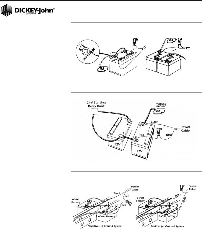
POWER CONNECTION
The Seed Manager® SE System operates on 12 volts DC only. The battery connections on the primary harness consist of two wires, each terminated with a ring terminal.
Before making the battery connections, determine the tractor battery arrangement from Figures 4, 5, and 6.
After the 12 volt source is known:
1.Connect the black wire directly to the negative (-) terminal of the battery.
2.Connect the red wire (containing the fuse link) to the positive (+) battery terminal.
3.Ensure the connections are clean and tight. Do not route these wires in close proximity to the existing battery cables.
4.Secure the battery wires with wire ties.
If the tractor battery arrangement differs from that shown or if any doubt exists about how to connect to the battery, use a volt meter first. Verify 11 to 14 volts across the battery connection points. On tractors using two batteries, be sure to make connections to the grounded battery.
Seed Manager SE® |
INSTALLATION AND SETUP / 7 |
11001-1359A-200810
OPERATOR’S MANUAL
Figure 4
12V Battery Source Connections
Vehicle
Ground
Power |
Black |
Power |
Red Cable |
|
Red |
Cable |
|
|
|
|
Black |
|
12V |
6V |
|
6V |
|
|
|
|
Vehicle
Ground
Figure 5
24V Battery Source Connections
Figure 6
Negative or Positive Source Connections
IMPORTANT: Before welding on the frame or chassis, be certain to disconnect battery leads. Failure to do so could result
in damage to the Seed Manager® SE.
8 / INSTALLATION AND SETUP |
Seed Manager SE |
11001-1359A-200810
OPERATOR’S MANUAL
IMPLEMENT HARNESS/MODULE CONNECTION
The Seed Manager® SE System uses any combination of three basic module types each with specific harness configurations.
Module Types:
•12 Row Material Flow
•16 Row Material Flow
•Shaft Speed
The following requirements must be observed when connecting modules to the bus:
•A maximum of six Material Flow Modules can be connected to the bus.
•Only one Shaft Speed Module can be connected to the bus.
•The Shaft Speed Module can be connected anywhere on the bus that is convenient and can be connected to either P1 or P2.
•A maximum of three Material Flow Modules can be connected to P1 or P2.
•Any combination of 12 Row or 16 Row Material Flow Modules can be used.
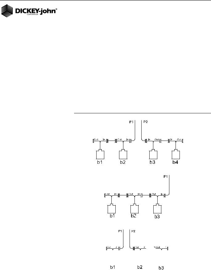
MODULE ORDER
IMPORTANT: The order in which Material Flow Modules are connected and their position on the toolbar or implement is important. The Material Flow Modules are identified by the console as b1, b2, ...bn (where n is the total number of Material Flow Modules connected). The order in which the console identifies the modules depend on how they are connected to the bus. Refer to (Figure 10) that shows example system configuration setups.
A single Bus cable connects to each module then serially (daisy chains) connects to following modules. The primary harness divides into two halves at the implement hitch (P1 and P2).
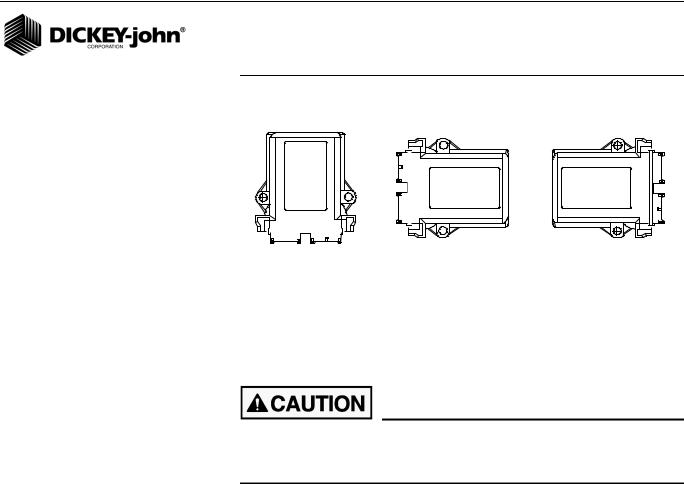
MODULE INSTALLATION
1.Select an area on the implement to mount the member that allows for easy hookup and access. Extensions can be used to reach members installed on remote areas of the implement.
Do not install the module in any orientation other than illustrated in (Figure 7). The connection wires must NOT be mounted upward as moisture can collect inside the unit and damage the circuits.
Ensure that module connectors do not face upward in a folded position as well.
Seed Manager SE |
INSTALLATION AND SETUP / 9 |
11001-1359A-200810
OPERATOR’S MANUAL
Figure 7
Material Flow Module
Preferred |
|
|
|
|
Acceptable |
Acceptable |
|||
|
|
|
|
|
|
|
|
|
|
|
|
|
|
|
|
|
|
|
|
|
|
|
|
|
|
|
|
|
|
|
|
|
|
|
|
|
|
|
|
|
|
|
|
|
|
|
|
|
|
|
|
|
|
|
|
|
|
|
|
2.Mount with the label side of the module facing out.
3.To bolt the member to a frame:
•Use the enclosure as a template to mark the location of the mounting holes.
•Drill two 9/32 inch diameter holes where marked.
•Attach to frame using 1/4 x 20 bolts or other fastening devices as illustrated in (Figure 8).
Do not use the enclosure as a guide when drilling. Do not overtighten nuts as this may damage the mounting tabs on the enclosure.
10 / INSTALLATION AND SETUP |
Seed Manager SE |
11001-1359A-200810

OPERATOR’S MANUAL
Figure 8
Material Flow Modules (using bolts)
IMPLEMENT
FRAME
1/4 FLAT WASHER
1/4 x 20 BOLT 
 1/4 NUT
1/4 SPLIT LOCKWASHER
IMPLEMENT
FRAME OR
SUPPORT
1/4 x 20 THREADED "U"
1/4 FLAT WASHER BOLT OR OTHER FASTENING DEVICE
1/4 NUT
1/4 SPLIT LOCKWASHER
4.To tie strap the member to a frame:
•Use one long tie-strap to loop around the member body and through both mounting holes as illustrated in (Figure 9).
•If necessary, drill mounting holes following the procedure described above.
•Securely tighten tie strap.
•Install a second tie strap toward the label end of the enclosure for additional support.
Figure 9
Material Flow Module Installation (Tie Strap)
IMPLEMENT
FRAME
Seed Manager SE® |
INSTALLATION AND SETUP / 11 |
11001-1359A-200810
OPERATOR’S MANUAL
5.Lay out each module harness along the frame of the implement to each of the seed rows (or appropriate sensors).
6.Secure the harness to the toolbar with a minimum of 3” straight wire exiting the module before bending and attaching with tie straps.
7.Install and/or connect each of the seed sensors (or appropriate sensor). Sensor mounting instructions accompany the sensor. Select the mounting location and install as described in the instructions.
8.Connect each module together with a bus harness.
IMPORTANT: Be sure the locking tabs engage when inserting the connectors. The connection is sealed when the locking tabs have fully engaged.
9.Connect the tractor harness P1 and P2 connectors to the bus harness.
10.Coil and secure existing cables with wire ties to avoid pinching or damage to the harness.
MODULE SETUP EXAMPLES
Figure 10
Four Module Setup (two modules are connected to P1 and two to P2)
Three Module Setup (All modules connected to P1)
Three Module Setup (one module connected to P1 and 2 connected to P2)
|
|
|
|
|
|
|
|
|
|
|
|
|
|
|
|
|
|
|
|
|
|
|
|
|
|
|
|
|
|
|
|
|
|
|
|
|
|
|
|
|
|
|
|
|
|
|
|
|
|
|
|
|
|
|
|
|
|
|
|
|
|
|
|
|
|
|
|
|
|
|
|
|
|
|
|
|
|
|
|
|
|
|
|
|
|
|
|
|
|
|
|
|
|
|
|
|
|
|
|
|
|
|
|
|
|
|
|
|
|
|
|
12 / INSTALLATION AND SETUP |
|
|
|
|
|
|
|
|
|
|
|
|
|
|
|
|
|
|
Seed Manager SE |
||||||||
11001-1359A-200810
OPERATOR’S MANUAL
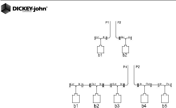
Two Module Setup (one module connected to both P1 and P2)
Two Module Setup (three modules connected to PA and 2 connected to P2)
As the previous examples show, b1 is always identified as the LAST module connected to P1. The remaining modules on P1 are numbered sequentially, along with any modules connected to P2.
Seed Manager SE |
INSTALLATION AND SETUP / 13 |
11001-1359A-200810
OPERATOR’S MANUAL
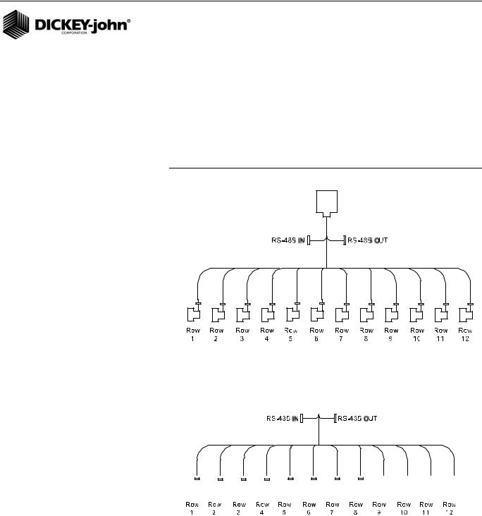
CONNECTING SENSORS TO MODULES
IMPORTANT: When connecting sensors to the Material Flow Modules, all seed sensors installed on a Material Flow Module must be connected sequentially starting with Row 1 as shown below.
When correctly connected, row 1 sensor should be connected to the Row 1 input on b1. The monitor will then number the sensors from 1 to n starting on b1, then b2, and so on.
Figure 11
Correct Install
Correct Install
|
|
|
|
|
|
|
|
|
|
|
|
|
|
|
|
|
|
|
|
|
|
|
|
|
|
|
|
|
|
|
|
|
|
|
|
|
|
|
|
|
|
|
|
|
|
|
|
|
|
|
|
|
|
|
|
|
|
|
|
|
|
|
|
|
|
|
|
|
|
|
|
|
|
|
|
|
|
|
|
|
|
|
|
|
|
|
|
|
|
|
|
|
|
|
|
|
|
|
|
|
|
|
|
|
|
|
|
|
|
|
|
|
|
|
|
|
|
|
|
|
|
|
|
|
|
|
|
|
|
|
|
|
|
|
|
|
|
|
|
|
|
|
|
|
|
|
|
|
|
|
|
|
|
|
|
|
|
|
|
|
|
|
|
|
|
|
|
|
|
|
|
|
|
|
|
|
|
|
|
|
|
|
|
|
|
|
|
|
|
|
|
|
|
|
|
|
|
|
|
|
|
|
|
|
|
|
|
|
|
|
|
|
|
|
|
|
|
|
|
|
|
|
|
|
|
|
|
|
|
|
|
|
|
|
|
|
|
|
|
|
|
|
|
|
|
|
|
|
|
|
|
|
|
|
|
|
|
|
|
|
|
|
|
|
|
|
|
|
|
|
|
|
|
|
|
|
|
|
|
|
|
|
|
|
|
|
|
|
|
|
|
|
|
|
|
|
|
|
|
|
|
|
|
|
|
|
|
|
|
|
|
|
|
|
|
|
|
|
|
|
|
|
|
|
|
|
|
|
|
|
|
|
|
|
|
|
|
|
|
|
|
|
|
|
|
|
|
|
|
|
|
|
|
|
|
|
|
|
|
|
|
|
|
|
|
|
|
|
|
|
|
|
|
|
|
|
|
|
|
|
|
|
|
|
|
|
|
|
|
|
|
|
|
|
|
|
|
|
|
|
|
|
|
|
|
|
14 / INSTALLATION AND SETUP |
|
|
|
|
|
|
|
|
|
|
Seed Manager SE |
|||||||||||||||||||||||||
11001-1359A-200810
OPERATOR’S MANUAL
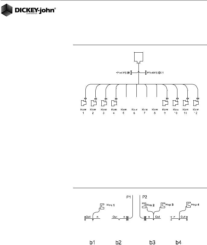
The following illustration shows eight row modules installed incorrectly.
IMPORTANT: There can be no skips in the row inputs on a Material
Flow Module.
Figure 12
Incorrect Install
HOPPER LEVEL SENSORS
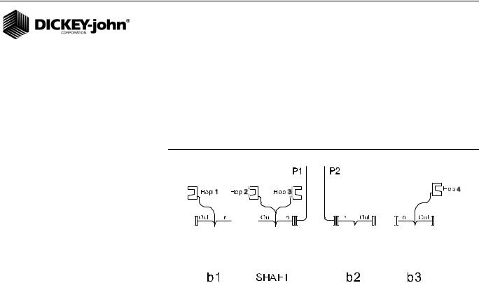
Hopper level sensors can be connected to 12 Row Material Flow Modules. Hopper sensors can be connected to either of the hopper inputs on a Material Flow Module. The monitor will identify the number of hopper sensors connected to each Material Flow Module and will number them from 1 to n starting with any sensors connected to b1. If no sensors are connected to b1, the number starts from b2 and so on.
In the event that two hopper sensors are connected to a given module, the sensor connected to input 1 is numbered before the sensor connected to input 2. The following shows an example configuration with hopper sensors connected and how they would be identified by the console.
Figure 13
Hopper Sensor Connection to 12 Row Material Flow Module
|
|
|
|
|
|
|
|
|
|
|
|
|
|
|
|
|
|
|
|
|
|
|
|
|
|
|
|
|
|
|
|
|
|
|
|
|
|
|
|
|
|
|
|
|
|
|
|
|
|
|
|
|
|
|
|
|
|
|
|
|
|
|
|
|
|
|
|
|
|
|
|
|
|
|
|
|
|
|
|
|
|
|
|
|
|
|
|
|
|
|
|
|
|
|
|
|
|
|
|
|
|
|
|
|
|
|
|
|
|
|
|
|
|
|
|
|
|
|
|
|
|
|
|
|
|
|
|
|
|
|
|
|
|
|
|
|
|
|
|
|
|
|
|
|
|
|
|
|
|
|
|
|
|
|
|
|
|
|
|
|
|
|
|
|
|
|
|
|
|
|
|
|
|
|
|
|
|
|
|
Seed Manager SE |
|
|
|
|
|
|
|
|
|
|
|
|
|
|
|
INSTALLATION AND SETUP / 15 |
|||||||||||||||||||
11001-1359A-200810
OPERATOR’S MANUAL
When hopper level sensors are connected to a Shaft Speed Module, they are numbered relative to the position of the Shaft Speed Module on the bus. If the Shaft Speed Module is connected to the RS-485 out of b1, the numbering of the hopper sensors starts with this module, then continues with any hopper sensors connected to b1, b2, etc. If the Shaft Speed Module is connected between Material Flow Modules, any hopper sensors connected are numbered in the order in which they are detected as shown below.
Figure 14
Hopper Sensor Connection to Shaft Speed Module
|
|
|
|
|
|
|
|
|
|
|
|
|
|
|
|
|
|
|
|
|
|
|
|
|
|
|
|
|
|
|
|
|
|
|
|
|
|
|
|
|
|
|
|
|
|
|
|
|
|
|
|
|
|
|
|
|
|
|
|
|
|
|
|
|
|
|
|
|
|
|
|
|
|
|
|
|
|
|
|
|
|
|
|
|
|
|
|
|
|
|
|
|
|
|
|
|
|
|
|
|
|
|
|
|
|
|
|
|
|
|
|
|
|
|
|
|
|
|
|
|
|
|
|
|
|
|
|
|
|
|
|
|
|
|
|
|
|
|
|
|
|
|
|
|
|
|
|
|
|
|
|
|
|
|
|
|
|
|
|
|
|
|
|
|
|
|
|
|
|
16 / INSTALLATION AND SETUP |
|
|
|
|
|
|
|
|
|
|
|
|
|
|
|
|
|
|
|
|
|
|
|
|
|
|
|
Seed Manager SE |
|||||
11001-1359A-200810
OPERATOR’S MANUAL
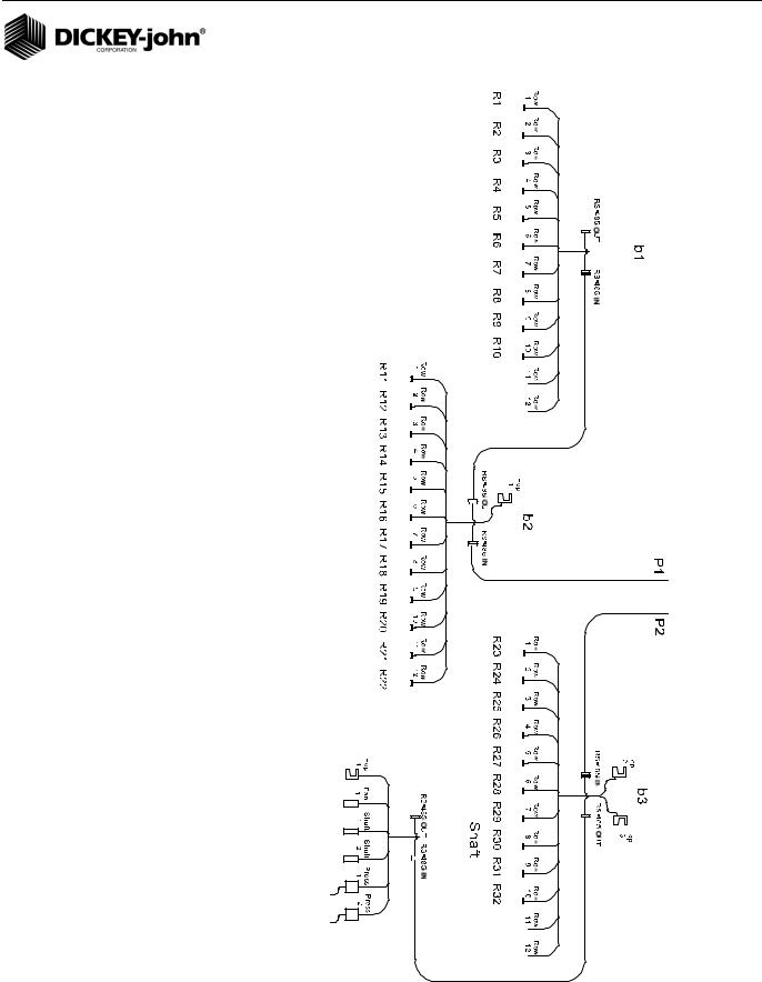
NOTE: Shaft, fan, and pressure |
Figure 15 |
|||||||||||||||||||||||||||||||||||||||||||
sensors can only be connected |
|
|
|
|
|
|
|
|
|
|
|
|
|
|
|
|
|
|
|
|
|
|
|
|
|
|
|
|
|
|
|
|
|
|
|
|
|
|
|
|
|
|
|
|
|
|
|
|
|
|
|
|
|
|
|
|
|
|
|
|
|
|
|
|
|
|
|
|
|
|
|
|
|
|
|
|
|
|
|
|
|
|
|
|
|
|
|
|
|
to the Shaft Speed Module. |
|
|
|
|
|
|
|
|
|
|
|
|
|
|
|
|
|
|
|
|
|
|
|
|
|
|
|
|
|
|
|
|
|
|
|
|
|
|
|
|
|
|
|
|
These sensors are identified by |
|
|
|
|
|
|
|
|
|
|
|
|
|
|
|
|
|
|
|
|
|
|
|
|
|
|
|
|
|
|
|
|
|
|
|
|
|
|
|
|
|
|
|
|
the monitor according to what |
|
|
|
|
|
|
|
|
|
|
|
|
|
|
|
|
|
|
|
|
|
|
|
|
|
|
|
|
|
|
|
|
|
|
|
|
|
|
|
|
|
|
|
|
input they are connected to |
|
|
|
|
|
|
|
|
|
|
|
|
|
|
|
|
|
|
|
|
|
|
|
|
|
|
|
|
|
|
|
|
|
|
|
|
|
|
|
|
|
|
|
|
|
|
|
|
|
|
|
|
|
|
|
|
|
|
|
|
|
|
|
|
|
|
|
|
|
|
|
|
|
|
|
|
|
|
|
|
|
|
|
|
|
|
|
|
|
regardless of the position of the |
|
|
|
|
|
|
|
|
|
|
|
|
|
|
|
|
|
|
|
|
|
|
|
|
|
|
|
|
|
|
|
|
|
|
|
|
|
|
|
|
|
|
|
|
Shaft Speed Module on the |
|
|
|
|
|
|
|
|
|
|
|
|
|
|
|
|
|
|
|
|
|
|
|
|
|
|
|
|
|
|
|
|
|
|
|
|
|
|
|
|
|
|
|
|
bus. (Figure 15) shows a |
|
|
|
|
|
|
|
|
|
|
|
|
|
|
|
|
|
|
|
|
|
|
|
|
|
|
|
|
|
|
|
|
|
|
|
|
|
|
|
|
|
|
|
|
complete example of a system |
|
|
|
|
|
|
|
|
|
|
|
|
|
|
|
|
|
|
|
|
|
|
|
|
|
|
|
|
|
|
|
|
|
|
|
|
|
|
|
|
|
|
|
|
|
|
|
|
|
|
|
|
|
|
|
|
|
|
|
|
|
|
|
|
|
|
|
|
|
|
|
|
|
|
|
|
|
|
|
|
|
|
|
|
|
|
|
|
|
setup and how each connected |
|
|
|
|
|
|
|
|
|
|
|
|
|
|
|
|
|
|
|
|
|
|
|
|
|
|
|
|
|
|
|
|
|
|
|
|
|
|
|
|
|
|
|
|
|
|
|
|
|
|
|
|
|
|
|
|
|
|
|
|
|
|
|
|
|
|
|
|
|
|
|
|
|
|
|
|
|
|
|
|
|
|
|
|
|
|
|
|
|
|
|
|
|
|
|
|
|
|
|
|
|
|
|
|
|
|
|
|
|
|
|
|
|
|
|
|
|
|
|
|
|
|
|
|
|
|
|
|
|
|
|
|
|
|
sensor would be identified. |
|
|
|
|
|
|
|
|
|
|
|
|
|
|
|
|
|
|
|
|
|
|
|
|
|
|
|
|
|
|
|
|
|
|
|
|
|
|
|
|
|
|
|
|
|
|
|
|
|
|
|
|
|
|
|
|
|
|
|
|
|
|
|
|
|
|
|
|
|
|
|
|
|
|
|
|
|
|
|
|
|
|
|
|
|
|
|
|
|
|
|
|
|
|
|
|
|
|
|
|
|
|
|
|
|
|
|
|
|
|
|
|
|
|
|
|
|
|
|
|
|
|
|
|
|
|
|
|
|
|
|
|
|
|
|
|
|
|
|
|
|
|
|
|
|
|
|
|
|
|
|
|
|
|
|
|
|
|
|
|
|
|
|
|
|
|
|
|
|
|
|
|
|
|
|
|
|
|
|
|
|
|
|
|
|
|
|
|
|
|
|
|
|
|
|
|
|
|
|
|
|
|
|
|
|
|
|
|
|
|
|
|
|
|
|
|
|
|
|
|
|
|
|
|
|
|
|
|
|
|
|
|
|
|
|
|
|
|
|
|
|
|
|
|
|
|
|
|
|
|
|
|
|
|
|
|
|
|
|
|
|
|
|
|
|
|
|
|
|
|
|
|
|
|
|
|
|
|
|
|
|
|
|
|
|
|
|
|
|
|
|
|
|
|
|
|
|
|
|
|
|
|
|
|
|
|
|
|
|
|
|
|
|
|
|
|
|
|
|
|
|
|
|
|
|
|
|
|
|
|
|
|
|
|
|
|
|
|
|
|
|
|
|
|
|
|
|
|
|
|
|
|
|
|
|
|
|
|
|
|
|
|
|
|
|
|
|
|
|
|
|
|
|
|
|
|
|
|
|
|
|
|
|
|
|
|
|
|
|
|
|
|
|
|
|
|
|
|
|
|
|
|
|
|
|
|
|
|
|
|
|
|
|
|
|
|
|
|
|
|
|
|
|
|
|
|
|
|
|
|
|
|
|
|
|
|
|
|
|
|
|
|
|
|
|
|
|
|
|
|
|
|
|
|
|
|
|
|
|
|
|
|
|
|
|
|
|
|
|
|
|
|
|
|
|
|
|
|
|
|
|
|
|
|
|
|
|
|
|
|
|
|
|
|
|
|
|
|
|
|
|
|
|
|
|
|
|
|
|
|
|
|
|
|
|
|
|
|
|
|
|
|
|
|
|
|
|
|
|
|
|
|
|
|
|
|
|
|
|
|
|
|
|
|
|
|
|
|
|
|
|
|
|
|
|
|
|
|
|
|
|
|
|
|
|
|
|
|
|
|
|
|
|
|
|
|
|
|
|
|
|
|
|
|
|
|
|
|
|
|
|
|
|
|
|
|
|
|
|
|
|
|
|
|
|
|
|
|
|
|
|
|
|
|
|
|
|
|
|
|
|
|
|
|
|
|
|
|
|
|
|
|
|
|
|
|
|
|
|
|
|
|
|
|
|
|
|
|
|
|
|
|
|
|
|
|
|
|
|
|
|
|
|
|
|
|
|
|
|
|
|
|
|
|
|
|
|
|
|
|
|
|
|
|
|
|
|
|
|
|
|
|
|
|
|
|
|
|
|
|
|
|
|
|
|
|
|
|
|
|
|
|
|
|
|
|
|
|
|
|
|
|
|
|
|
|
|
|
|
|
|
|
|
|
|
|
|
|
|
|
|
|
|
|
|
|
|
|
|
|
|
|
|
|
|
|
|
|
|
|
|
|
|
|
|
|
|
|
|
|
|
|
|
|
|
|
|
|
|
|
|
|
|
|
|
|
|
|
|
|
|
|
|
|
|
|
|
|
|
|
|
|
|
|
|
|
|
|
|
|
|
|
|
|
|
|
|
|
|
|
|
|
|
|
|
|
|
|
|
|
|
|
|
|
|
|
|
|
|
|
|
|
|
|
|
|
|
|
|
|
|
|
|
|
|
|
|
|
|
|
|
|
|
|
|
|
|
|
|
|
|
|
|
|
|
|
|
|
|
|
|
|
|
|
|
|
|
|
|
|
|
|
|
|
|
|
|
|
|
|
|
|
|
|
|
|
|
|
|
|
|
|
|
|
|
|
|
|
|
|
|
|
|
|
|
|
|
|
|
|
|
|
|
|
|
|
|
|
|
|
|
|
|
|
|
|
|
|
|
|
|
|
|
|
|
|
|
|
|
|
|
|
|
|
|
|
|
|
|
|
|
|
|
|
|
|
|
|
|
|
|
|
|
|
|
|
|
|
|
|
|
|
|
|
|
|
|
|
|
|
|
|
|
|
|
|
|
|
|
|
|
|
|
|
|
|
|
|
|
|
|
|
|
|
|
|
|
|
|
|
|
|
|
|
|
|
|
|
|
|
|
|
|
|
|
|
|
|
|
|
|
|
|
|
|
|
|
|
|
|
|
|
|
|
|
|
|
|
|
|
|
|
|
|
|
|
|
|
|
|
|
|
|
|
|
|
|
|
|
|
|
|
|
|
|
|
|
|
|
|
|
|
|
|
|
|
|
|
|
|
|
|
|
|
|
|
|
|
|
|
|
|
|
|
|
|
|
|
|
|
|
|
|
|
|
|
|
|
|
|
|
|
|
|
|
|
|
|
|
|
|
|
|
|
|
|
|
|
|
|
|
|
|
|
|
|
|
|
|
|
|
|
|
|
|
|
|
|
|
|
|
|
|
|
|
|
|
|
|
|
|
|
|
|
|
|
|
|
|
|
|
|
|
|
|
|
|
|
|
|
|
|
|
|
|
|
|
|
|
|
|
|
|
|
|
|
|
|
|
|
|
|
|
|
|
|
|
|
|
|
|
|
|
|
|
|
|
|
|
|
|
|
|
|
|
|
|
|
|
|
|
|
|
|
|
|
|
|
|
|
|
|
|
|
|
|
|
|
|
|
|
|
|
|
|
|
|
|
|
|
|
|
|
|
|
|
|
|
|
|
|
|
|
|
|
|
|
|
|
|
|
|
|
|
|
|
|
|
|
|
|
|
|
|
|
|
|
|
|
|
|
|
|
|
|
|
|
|
|
|
|
|
|
|
|
|
|
|
|
|
|
|
|
|
|
|
|
|
|
|
|
|
|
|
|
|
|
|
|
|
|
|
|
|
|
|
|
|
|
|
|
|
|
|
|
|
|
|
|
|
|
|
|
|
|
|
|
|
|
|
|
|
|
|
|
|
|
|
|
|
|
|
|
|
|
|
|
|
|
|
|
|
|
|
|
|
|
|
|
|
|
|
|
|
|
|
|
|
|
|
|
|
|
|
|
|
|
|
|
|
|
|
|
|
|
|
|
|
|
|
|
|
|
|
|
|
|
|
|
|
|
|
|
|
|
|
|
|
|
|
|
|
|
|
|
|
|
|
|
|
|
|
|
|
|
|
|
|
|
|
|
|
|
|
|
|
|
|
|
|
|
|
|
|
|
|
|
|
|
|
|
|
|
|
|
|
|
|
|
|
|
|
|
|
|
|
|
|
|
|
|
|
|
|
|
|
|
|
|
|
|
|
|
|
|
|
|
|
|
|
|
|
|
|
|
|
|
|
|
|
|
|
|
|
|
|
|
|
|
|
|
|
|
|
|
|
|
|
|
|
|
|
|
|
|
|
|
|
|
|
|
|
|
|
|
|
|
|
|
|
|
|
|
|
|
|
|
|
|
|
|
|
|
|
|
|
|
|
|
|
|
|
|
|
|
|
|
|
|
|
|
|
|
|
|
|
|
|
|
|
|
|
|
|
|
|
|
|
|
|
|
|
|
|
|
|
|
|
|
|
|
|
|
|
|
|
|
|
|
|
|
|
|
|
|
|
|
|
|
|
|
|
|
|
|
|
|
|
|
|
|
|
|
|
|
|
|
|
|
|
|
|
|
|
|
|
|
|
|
|
|
|
|
|
|
|
|
|
|
|
|
|
|
|
|
|
|
|
|
|
|
|
|
|
|
|
|
|
|
|
|
|
|
|
|
|
|
|
|
|
|
|
|
|
|
|
|
|
|
|
|
|
|
|
|
|
|
|
|
|
|
|
|
|
|
|
|
|
|
|
|
|
|
|
|
|
|
|
|
|
|
|
|
|
|
|
|
|
|
|
|
|
|
|
|
|
|
|
|
|
|
|
|
|
|
|
|
|
|
|
|
|
|
|
|
|
|
|
|
|
|
|
|
|
|
|
|
|
|
|
|
|
|
|
|
|
|
|
|
|
|
|
|
|
|
|
|
|
|
|
|
|
|
|
|
|
|
|
|
|
|
|
|
|
|
|
|
|
|
|
|
|
|
|
|
|
|
|
|
|
|
|
|
|
|
|
|
|
|
|
|
|
|
|
|
|
|
|
|
|
|
|
|
|
|
|
|
|
|
|
|
|
|
|
|
|
|
|
|
|
|
|
|
|
|
|
|
|
|
|
|
|
|
|
|
|
|
|
|
|
|
|
|
|
|
|
|
|
|
|
|
|
|
|
|
|
|
|
|
|
|
|
|
|
|
|
|
|
|
|
|
|
|
|
|
|
|
|
|
|
|
|
|
|
|
|
|
|
|
|
|
|
|
|
|
|
|
|
|
|
|
|
|
|
|
|
|
|
|
|
|
|
|
|
|
|
|
|
|
|
|
|
|
|
|
|
|
|
|
|
|
|
|
|
|
|
|
|
|
|
|
|
|
|
|
|
|
|
|
|
|
|
|
|
|
|
|
|
|
|
|
|
|
|
|
|
|
|
|
|
|
|
|
|
|
|
|
|
|
|
|
|
|
|
|
|
|
|
|
|
|
|
|
|
|
|
|
|
|
|
|
|
|
|
|
|
|
|
|
|
|
|
|
|
|
|
|
|
|
|
|
|
|
|
|
|
|
|
|
|
|
|
|
|
|
|
|
|
|
|
|
|
|
|
|
|
|
|
|
|
|
|
|
|
|
|
|
|
|
|
|
|
|
|
|
|
|
|
|
|
|
|
|
|
|
|
|
|
|
|
|
|
|
|
|
|
|
|
|
|
|
|
|
|
|
|
|
|
|
|
|
|
|
|
|
|
|
|
|
|
|
|
|
|
|
|
|
|
|
|
|
|
|
|
|
|
|
|
|
|
|
|
|
|
|
|
|
|
|
|
|
|
|
|
|
|
|
|
|
|
|
|
|
|
|
|
|
|
|
|
|
|
|
|
|
|
|
|
|
|
|
|
|
|
|
|
|
|
|
|
|
|
|
|
|
|
|
|
|
|
|
|
|
|
|
|
|
|
|
|
|
|
|
|
|
|
|
|
|
|
|
|
|
|
|
|
|
|
|
Seed Manager SE |
INSTALLATION AND SETUP / 17 |
11001-1359A-200810

OPERATOR’S MANUAL
HARNESSES
12 ROW HARNESS
16 ROW HARNESS
18 / INSTALLATION AND SETUP
Seed Manager SE
11001-1359A-200810
OPERATOR’S MANUAL
SHAFT SPEED MODULE HARNESS
RS485 EXTENSION HARNESS
Seed Manager SE® |
INSTALLATION AND SETUP / 19 |
11001-1359A-200810

OPERATOR’S MANUAL
20 / INSTALLATION AND SETUP |
Seed Manager SE |
11001-1359A-200810
 Loading...