


 Loading...
Ariens 915501 1844, 915313 2252, 915041 2252, 915037 1844, 915036 ZT1844 User Manual
...
Zoom
Service Manual
Ariens Models 915035, 037, 039, 041, 313, 501
Gravely Models 915034, 036, 038, 040
00173200 09/03 Printed in USA

TABLE OF CONTENTS
Section 1 - Introduction . . . . . . . . . . . . . . . . . . 1-2
1.1 The Manual . . . . . . . . . . . . . . . . . . . . . . . . . . . . . 1-2 1.2 Service And Replacement Parts . . . . . . . . . . . . . 1-2 1.3 Product Registration. . . . . . . . . . . . . . . . . . . . . . . 1-2 1.4 Unauthorized Replacement Parts . . . . . . . . . . . . 1-2 1.5 Disclaimer. . . . . . . . . . . . . . . . . . . . . . . . . . . . . . . 1-2 1.6 Technical Service Communications . . . . . . . . . . . 1-2
Section 2 - Safety . . . . . . . . . . . . . . . . . . . . . . . . 2-3
2.1 Safety Alerts . . . . . . . . . . . . . . . . . . . . . . . . . . . . . 2-3 2.2 Signal Words . . . . . . . . . . . . . . . . . . . . . . . . . . . . 2-3 2.3 Notations . . . . . . . . . . . . . . . . . . . . . . . . . . . . . . . 2-3 2.4 Practices And Laws . . . . . . . . . . . . . . . . . . . . . . . 2-3 2.5 Required Operator Training . . . . . . . . . . . . . . . . . 2-3 2.6 Preparation. . . . . . . . . . . . . . . . . . . . . . . . . . . . . . 2-3 2.7 Service Position . . . . . . . . . . . . . . . . . . . . . . . . . . 2-3 2.8 Cleaning And Storage . . . . . . . . . . . . . . . . . . . . . 2-3 2.9 Safety Rules. . . . . . . . . . . . . . . . . . . . . . . . . . . . . 2-4
Section 3 - Specifications . . . . . . . . . . . . . . . . . 3-6
Section 4 - General Maintenance
& Adjustments . . . . . . . . . . . . . . . . . . . . . . . 4-8
4.1 Controls And Features . . . . . . . . . . . . . . . . . . . . . 4-8 4.2 Fuel Level. . . . . . . . . . . . . . . . . . . . . . . . . . . . . . . 4-9 4.3 Maintenance Schedule. . . . . . . . . . . . . . . . . . . . . 4-9 4.4 Remove Mower Deck. . . . . . . . . . . . . . . . . . . . . 4-12 4.5 Level and Adjust Pitch Of Mower Deck . . . . . . . 4-12 4.6 Hydrostatic Transmission Neutral Adjustment . . 4-13 4.7 Adjusting Unit to Track Straight . . . . . . . . . . . . . 4-13 4.8 Steering Lever Adjustments . . . . . . . . . . . . . . . . 4-14 4.9 Adjusting the Parking Brake. . . . . . . . . . . . . . . . 4-15
Section 5 - Engine . . . . . . . . . . . . . . . . . . . . . . 5-16
5.1 Engine Troubleshooting . . . . . . . . . . . . . . . . . . . 5-16 5.2 Checking Engine Oil. . . . . . . . . . . . . . . . . . . . . . 5-17 5.3 Changing Oil. . . . . . . . . . . . . . . . . . . . . . . . . . . . 5-17 5.4 Checking Engine Cooling. . . . . . . . . . . . . . . . . . 5-17 5.5 Cleaning The Air Cleaner. . . . . . . . . . . . . . . . . . 5-17 5.6 Changing The Air Cleaner Element . . . . . . . . . . 5-17 5.7 Inspect Muffler/Spark Arrester . . . . . . . . . . . . . . 5-17 5.8 Replace Spark Plugs . . . . . . . . . . . . . . . . . . . . . 5-17 5.9 Engine Removal. . . . . . . . . . . . . . . . . . . . . . . . . 5-17 5.10 Engine Installation . . . . . . . . . . . . . . . . . . . . . . 5-18
Section 6 - Mower Deck. . . . . . . . . . . . . . . . . . 6-19
6.1 Clutch To Deck Drive Belt Replacement . . . . . . 6-19 6.2 Check Blades . . . . . . . . . . . . . . . . . . . . . . . . . . . 6-19
6.3 Sharpening Mower Blade. . . . . . . . . . . . . . . . . . 6-20
Section 7 - Drive Train . . . . . . . . . . . . . . . . . . . 7-21
7.1 Hydro Transmission Troubleshooting . . . . . . . . 7-21
7.2 Hydrostatic Belt Replacement . . . . . . . . . . . . . . 7-22
7.3 Hydro-Gear Fluid Recommendations . . . . . . . . 7-22
7.4 Hydro-gear Transmission Removal . . . . . . . . . . 7-22
7.5 Hydro-Gear Transmission Installation . . . . . . . . 7-23
7.6 Electric Clutch Adjustment. . . . . . . . . . . . . . . . . 7-23
Section 8 - Lift System. . . . . . . . . . . . . . . . . . . 8-25
8.1 Lift System . . . . . . . . . . . . . . . . . . . . . . . . . . . . . 8-25
Section 9 - Fuel System. . . . . . . . . . . . . . . . . . 9-26
9.1 Fuel System Troubleshooting . . . . . . . . . . . . . . 9-26
9.2 Fuel Pump . . . . . . . . . . . . . . . . . . . . . . . . . . . . . 9-27.
9.3 Fuel System Contamination. . . . . . . . . . . . . . . . 9-27
9.4 Fuel Tank . . . . . . . . . . . . . . . . . . . . . . . . . . . . . . 9-27
Section 10 - Electrical . . . . . . . . . . . . . . . . . . 10-28
10.1 Tools. . . . . . . . . . . . . . . . . . . . . . . . . . . . . . . . 10-28
10.2 Electrical Measurements . . . . . . . . . . . . . . . . 10-28
10.3 Battery . . . . . . . . . . . . . . . . . . . . . . . . . . . . . . 10-29
10.4 Switches. . . . . . . . . . . . . . . . . . . . . . . . . . . . . 10-32
10.5 Solenoid And Relays . . . . . . . . . . . . . . . . . . . 10-33
10.6 Lighting Circuits . . . . . . . . . . . . . . . . . . . . . . . 10-33
10.7 Fuses . . . . . . . . . . . . . . . . . . . . . . . . . . . . . . . 10-34
10.8 Diodes And Rectifiers . . . . . . . . . . . . . . . . . . 10-34
10.9 Electric Clutch . . . . . . . . . . . . . . . . . . . . . . . . 10-34
10.10 Electrical . . . . . . . . . . . . . . . . . . . . . . . . . . . 10-34
10.11 Wiring Diagrams. . . . . . . . . . . . . . . . . . . . . . 10-36
10.12 Continuity Diagram . . . . . . . . . . . . . . . . . . . 10-40
10.13 Electrical System . . . . . . . . . . . . . . . . . . . . . 10-41
Section 11 - Mower Attachment . . . . . . . . . . 11-42
11.1 Mower Spindle Removal . . . . . . . . . . . . . . . . 11-42
1

SECTION 1 - INTRODUCTION
1.1 THE MANUAL
The purpose of this manual is to provide complete instructions for service, maintenance, disassembly, repair, and installation of the mechanical components for the 915 Zoom.
Dealer trained service personnel should use this manual as a supplement to and reminder of the training sessions conducted by the company.
Read all information for servicing a part or system before repair work is started to avoid needless disassembly.
Operation
Before operation of the unit, carefully and completely read manuals supplied with the unit. The contents will provide you with an understanding of safety instructions and controls during normal operation and maintenance.
Safety Messages
For your safety and the safety of others always read, understand, and follow all DANGER, WARNING, and CAUTION messages found in manuals and on safety decals.
Directional Reference
All reference to left, right, front, or rear are given from the operator in the operator position and facing the direction of forward travel.
1.2 SERVICE AND REPLACEMENT PARTS
When ordering publications, replacement parts, or making service inquiries, know the Model and Serial numbers of your unit and engine.
Numbers are located on the product registration form in the unit literature package. They are printed on a serial number label, located on the frame of your unit.
Engine Serial Number
Unit Serial Number
Figure 1
1.3 PRODUCT REGISTRATION
A warranty registration card must be filled out, signed, and returned at time of purchase. This card activates the warranty. Claims meeting requirements during limited warranty period will be honored.
1.4 UNAUTHORIZED REPLACEMENT PARTS
Use only Ariens/Gravely replacement parts. The replacement of any part on this vehicle with anything other than a Ariens/Gravely authorized replacement part may adversely affect the performance, durability, or safety of this unit and may void the warranty. Ariens/ Gravely disclaims liability for any claims or damages, whether warranty, property damage, personal injury, or death arising out of the use of unauthorized replacement parts.
1.5 DISCLAIMER
Ariens/Gravely reserves the right to discontinue, make changes to, and add improvements upon its products at any time without public notice or obligation. The descriptions and specifications contained in this manual were in effect at printing. Equipment described within this manual may be optional. Some illustrations may not be applicable to your unit.
1.6 TECHNICAL SERVICE COMMUNICATIONS
Ariens/Gravely Technical Service communicates information to the field using Service Letters, Service Bulletins, Product Notices, and Campaigns. Each communication signifies a type of information and priority. The dealer is responsible to carry out the directive provided in the communication. The types of communication are:
Service Letter - General technical information for the dealer. Technical information on how to service the product and product improvements.
Service Bulletin - Notification to update products to resolve certain issues or a notification of a policy change.
Product Notices - Notification of limited product located in a certain region. This is a limited distribution to only those who received the product involved.
Campaigns - Notification of a safety related issue. All products must be updated and are tracked by the factory until all units are corrected.
1 - 2
SECTION 2 - SAFETY
2.1 SAFETY ALERTS
Look for these symbols to point out important safety precautions. They mean:
Attention!
Personal Safety Is Involved! Become Alert!
Obey The Message!
2.2 SIGNAL WORDS
The safety alert symbol is used in decals on the unit and with proper operation procedures in this manual. They alert you to the existence and relative degree of hazards.
Understand the safety message. It contains important information about personal safety on or near the unit.
DANGER: IMMINENTLY HAZARDOUS SITUATION! If not avoided, WILL RESULT in death or serious injury.
WARNING: POTENTIALLY HAZARDOUS SITUATION! If not avoided, COULD RESULT in death or serious injury.
CAUTION: POTENTIALLY HAZARDOUS SITUATION! If not avoided, MAY RESULT in minor or moderate injury. It may also be used to alert against unsafe practices.
2.3 NOTATIONS
NOTE: General reference information for proper operation and maintenance practices.
IMPORTANT: Specific procedures or information required to prevent damage to unit or attachment.
2.4 PRACTICES AND LAWS
Practice usual and customary safe working precautions, for the benefit of yourself and others. Understand and follow all safety messages. Be alert to unsafe conditions and the possibility of minor, moderate, or serious injury or death. Learn applicable rules and laws in your area.
2.5 REQUIRED OPERATOR TRAINING
Original purchaser of this unit was instructed by the seller on safe and proper operation. If unit is to be used by someone other than original purchaser; loaned,
rented or sold, ALWAYS provide the Operator’s Manual and any needed safety training before operation.
2.6 PREPARATION
Before starting any removal of parts, proper preparation is very important for efficient work. A clean work area at the start of each job will allow you to perform service repairs easily and quickly.
To reduce the incidence of misplaced tools or parts, place removed components with all attaching hardware in the disassembly order on a clean work surface. Organization is a key part of proper reassembly.
Tools, instruments, and parts needed for the job should be gathered before work is started. Interrupting a job to locate tools or parts is a needless delay. A list of required special tools has been included in this manual.
CAUTION: Remove enough fuel so that no spillage will occur. Remove battery to prevent spillage of electrolyte.
2.7 SERVICE POSITION
WARNING: Always block wheels and know that jack stands or blocks used are stable, strong, or secure and will hold the weight of the unit during maintenance.
To ensure the unit is positioned in the proper service position:
1.Place jack stands under rear transaxle only.
2.If jacks are not available, place support blocks under transaxle at the rear of unit.
2.8 CLEANING AND STORAGE
IMPORTANT: To help prevent sealed bearing rust or corrosion never spray unit with water or store unit outdoors. Water can seep into sealed bearings and reduce component life. Bearings are sealed against dirt and debris only.
A unit that is excessively dirty should be cleaned before work starts. Cleaning will occasionally uncover trouble sources. Dirt and abrasive dust reduce the efficient work life of parts and can lead to costly replacement.
When taking unit out of extended storage:
1.Check for any damage or loose parts. Repair replace, or tighten hardware before operation.
2 - 3
2.If a preservative fluid was used in fuel tank, drain and discard. Fill fuel tank with fresh new fuel.
2.9 SAFETY RULES
Walk Around Inspection
Complete a walk around inspection of unit and work area to understand:
•Work area.
•Your unit.
•All safety decals.
Work Area
ALWAYS check overhead and side clearances carefully before operation. ALWAYS be aware of traffic when operating along streets or curbs.
ALWAYS keep hands and feet within the limits of the unit.
Keep children, people, and animals away. Keep children out of work area and under watchful care of a responsible adult.
Keep area of operation clear of all toys, pets, and debris. Objects can cause vehicle instability and injury.
Check for weak spots on dock, ramps or floors. Avoid uneven work areas and rough terrain. Stay alert for hidden hazards.
DO NOT run engine in an enclosed area. Always provide good ventilation.
Unit
ALWAYS keep protective structures, guards, and panels in good condition, in place and securely fastened. NEVER modify or remove safety devices.
Check Safety Interlock System for proper operation daily (see Operation section). Do not operate unless system operates properly.
Operation
Understand:
•How to operate all controls
•The functions of all controls
•How to STOP in an Emergency
•Speed ranges
Do not operate any of the control levers or power takeoff unless both feet are resting on the platform.
DO NOT travel at too fast a rate. DO NOT change engine governor settings or over-speed engine.
Always back up slowly. Always look down and behind before and while backing.
Never leave a running unit unattended. ALWAYS shut off power take off, lower throttle setting, and stop engine before leaving unit. ALWAYS remove key to prevent unauthorized use.
Never carry passengers on any part of unit.
Avoid uneven and rough terrain. DO NOT operate near drop offs, ditches, or embankments. Unit can suddenly turn over if a wheel is over the edge of a cliff or ditch, or if an edge caves in.
If tires lose traction, turn off power take off and proceed slowly straight down slope. Avoid wet surfaces.
Avoid parking on a slope. If necessary, use wheel chocks.
DO NOT leave unit unattended on a slope. ALWAYS use wheel chocks when leaving unit.
ALWAYS operate unit in good visibility and light.
Fuel is highly flammable and its vapors can explode. Use ONLY approved fuel containers.
NO Smoking!
NO Sparks!
NO Flames!
Allow engine to cool before servicing.
NEVER fill fuel tank when engine is running, hot, or unit is indoors.
Abnormal Vibrations are a warning of trouble. Striking a foreign object can damage unit. Immediately stop unit and engine. Remove key and wait for all moving parts to stop. Remove wire from spark plug. Inspect unit and make any necessary repairs before restart.
Hazardous Slopes
DO NOT operate on steep slopes. Avoid operating on slopes. When you must operate on a slope, travel up and down the slope. Never operate across a slope.
Never operate on a slope greater than 10 degrees.
Child Safety
NEVER allow children to operate or play on or near unit. Be alert and shut off unit if children enter area.
Personal Safety
Read and obey all warning, caution, and instructions on the unit and in provided manuals.
•Only trained adults may operate unit.
•Training includes actual operation.
•Clearly understand instructions.
•Be alert! Conditions can change.
NEVER operate unit after or during the use of medication, drugs or alcohol. Safe operation requires your complete and unimpaired attention at all times.
NEVER allow anyone to operate the unit when their alertness or coordination is impaired.
DO NOT operate unit without wearing adequate outer garments. Wear adequate safety gear and protective gloves. Wear proper footwear to improve footing on slippery surfaces.
Protect eyes, face, and head from objects that may be thrown from unit. Wear appropriate hearing protection.
2 - 4
Avoid Sharp Edges. Sharp edges can cut. Moving parts can cut or amputate fingers or a hand. Wear gloves to service unit when handling sharp edges.
ALWAYS keep hands away from any pinch points.
ALWAYS keep hands and feet away from all moving parts during operation. Moving parts can cut off body parts.
DO NOT touch unit parts which might be hot from operation. Allow parts to cool before attempting to maintain, adjust, or service.
Controls
Come to a complete stop before reversing.
Never jerk the control levers. Always use a steady even action to achieve smooth control.
Always be aware of obstructions that may cause injury to operator or damage to the unit.
Maintenance
ALWAYS maintain unit in safe operating condition. Damaged or worn out muffler can cause fire or explosion.
Check the conditions of the unit at the end of each day and repair any damage or defects.
ALWAYS block wheels and know all jack stands are strong and secure and will hold weight of unit during maintenance.
Keep nuts and bolts tight and keep equipment in safe operating conditions.
Before maintenance, adjustments, or service (except where specifically recommended), shut off engine.
Allow hot parts to cool.
Keep unit free of dirt, stones, and other debris. Clean up oil or fuel spills.
Storage
DO NOT store unit inside a building with fuel in the fuel tank where any ignition sources are present. Allow unit to cool completely.
ALWAYS clean unit before extended storage. See Engine Manual for proper storage.
Battery
Avoid Electric Shock. DO NOT reverse battery connections.
Explosive Gases! Poisonous battery fluid contains sulfuric acid and its contact with skin, eyes, or clothing can cause severe burns.
No flames. No sparks. No smoking near battery.
Always wear safety glasses and protective gear near battery.
DO NOT TIP battery beyond a 45o angle in any direction.
ALWAYS KEEP BATTERIES OUT OF REACH of children.
Transport
Use extra care when loading or unloading unit onto trailer or truck. Secure unit chassis to transport vehicle. NEVER secure from rods or linkages that could be damaged.
DO NOT transport with attachment in raised position.
Lower attachment when unit is parked or stored unless a positive mechanical lock is used.
Attachments and Accessories
Use only attachments or accessories designed for your unit.
2 - 5

SECTION 3 - SPECIFICATIONS
Ariens Models
Model Number |
915035 |
915037 |
|
915039 |
|
915041 |
915501 |
|
915313 |
Description |
1640 |
1844 |
|
2048 |
|
2252 |
1844 |
|
2252 |
Engine |
Single |
Cylinder |
|
|
Twin Cylinder Briggs & Stratton |
|
|||
|
Briggs & Stratton |
|
|
|
|
|
|
|
|
Engine Power - HP (kW) @ governed |
16 (11.9) |
18 (13.4) |
|
20 (14.9) |
|
22 (16.4) |
18 (12.8) |
|
22 (13.5) |
RPM |
|
|
|
|
|
|
|
|
|
Max Governed RPM |
|
3400 |
|
|
2900 |
|
3100 |
||
Fuel Tank Capacity - gal. (L) |
|
|
|
8 (30.28) |
|
|
|
||
Starter |
|
|
|
Electric |
|
|
|
||
Transmission |
|
|
|
Hydrostatic |
|
|
|
||
Speed: Forward Max. - mph (km/h) |
|
|
|
6.5 (10.5) |
|
|
|
||
Reverse Max. - mph (km/h) |
|
|
|
3 (3.2) |
|
|
|
||
PTO |
|
|
|
Electric Clutch/Brake |
|
|
|
||
Battery |
|
|
12 Volt Maintenance Free |
|
|
|
|||
Brakes |
|
|
|
Internal Transmission |
|
|
|
||
Cutting Height - in. (cm) |
|
|
|
1-1/2 - 4-1/2 (3.81 - 11.4) |
|
|
|
||
Cutting Width - in. (cm) |
40 (102) |
44 (112) |
|
48 (122) |
|
52 (132) |
44 (112) |
|
52 (132) |
Tire Pressure: Front - psi (kPa) |
46 (317) |
|
|
|
|
46 (317) |
|
|
|
Rear - psi (kPa) |
10 (69) |
|
|
|
12 (83) |
|
|
|
|
Tire Size: Front - in. (cm) |
11 x 4 |
|
|
11 x 4 (27.9 x 10.2) |
|
||||
|
(27.9 x |
|
|
|
|
|
|
|
|
|
10.2) |
|
|
|
|
|
|
|
|
Rear - in. (cm) |
18 x 8.5 |
|
|
18 x 9.5 (45.7 x 24.1) |
|
||||
(45.7 x |
|
|
|
||||||
|
|
|
|
|
|
|
|
|
|
|
21.6) |
|
|
|
|
|
|
|
|
Turning Radius |
|
|
|
Zero |
|
|
|
||
Weight - lbs (kg) |
660 (299) |
687 (312) |
|
714 (324) |
|
740 (336) |
687 (312) |
|
740 (336) |
Height - in. (cm) |
|
|
|
41 |
(104) |
|
|
|
|
Length - in. (cm) |
|
|
|
76 (193) |
|
|
|
||
Width - in. (cm) |
44 (112) |
|
|
|
46.5 (118) |
|
|
|
|
Max. Towing Capacity - lbs (kg) |
|
|
|
300 (136) |
|
|
|
||
Max. Tongue Weight - lbs (kg) |
|
|
|
30 (13.6) |
|
|
|
||
CE Sound and Vibration |
|
|
|
|
|
|
|
|
|
Oper. Ear Sound Pressure (Lpa) in dBA |
|
NA |
|
|
|
86 |
|
91 |
|
Vibration Measure (m/sec2) |
|
|
|
|
|
|
|
|
|
At Operator Hands: X axis |
|
NA |
|
|
|
.76 |
|
2.6 |
|
Y axis |
|
|
|
|
|
|
.59 |
|
1.1 |
Z axis |
|
|
|
|
|
|
1.10 |
|
1.8 |
At Operator Feet: X axis |
|
NA |
|
|
|
.34 |
|
.34 |
|
Y axis |
|
|
|
|
|
|
.42 |
|
.42 |
Z axis |
|
|
|
|
|
|
1.19 |
|
1.2 |
At Operator Seat: X axis |
|
NA |
|
|
|
.35 |
|
.35 |
|
Y axis |
|
|
|
|
|
|
.37 |
|
.37 |
Z axis |
|
|
|
|
|
|
.87 |
|
.87 |
3 - 6
Gravely Models
Model Number |
915034 |
915036 |
|
915038 |
915040 |
Description |
ZT1640 |
ZT1844 |
|
ZT2048 |
ZT2252 |
Engine |
Single |
Cylinder |
|
Twin Cylinder |
Briggs & Stratton |
|
Briggs & Stratton |
|
|
|
|
Engine Power - HP (kW) @ governed |
16 (11.9) |
18 (13.4) |
|
20 (14.9) |
22 (16.4) |
RPM |
|
|
|
|
|
Max Governed RPM |
|
|
3400 |
|
|
Fuel Tank Capacity - gal. (L) |
|
|
8 (30.28) |
|
|
Starter |
|
|
Electric |
|
|
Transmission |
|
|
Hydrostatic |
|
|
Speed: Forward Max. - mph (km/h) |
|
|
6.5 (10.5) |
|
|
Reverse Max. - mph (km/h) |
|
|
3 (3.2) |
|
|
PTO |
|
Electric Clutch/Brake |
|
||
Battery |
|
12 Volt Maintenance Free |
|
||
Brakes |
|
Internal Transmission |
|
||
Cutting Height - in. (cm) |
|
1-1/2 - 4-1/2 (3.81 - 11.4) |
|
||
Cutting Width - in. (cm) |
40 (102) |
44 (112) |
|
48 (122) |
52 (132) |
Tire Pressure: Front - psi (kPa) |
46 (317) |
|
|
46 (317) |
|
Rear - psi (kPa) |
10 (69) |
|
12 (83) |
|
|
Tire Size: Front - in. (cm) |
11 x 4 |
|
|
11 x 4 (27.9 x 10.2) |
|
|
(27.9 x 10.2) |
|
|
|
|
|
18 x 8.5 |
|
|
|
|
Rear - in. (cm) |
(45.7 x 21.6) |
|
|
18 x 9.5 (45.7 x 24.1) |
|
Turning Radius |
|
|
Zero |
|
|
Weight - lbs (kg) |
660 (299) |
687 (312) |
|
714 (324) |
740 (336) |
Height - in. (cm) |
|
|
41 |
(104) |
|
Length - in. (cm) |
|
|
76 (193) |
|
|
Width - in. (cm) |
44 (112) |
|
46.5 (118) |
|
|
Max. Towing Capacity - lbs (kg) |
|
|
300 (136) |
|
|
Max. Tongue Weight - lbs (kg) |
|
|
30 (13.6) |
|
|
3 - 7
SECTION 4 - GENERAL MAINTENANCE & ADJUSTMENTS
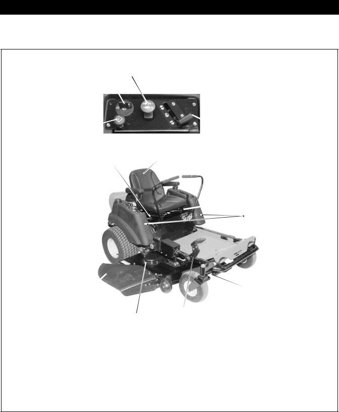
4.1 CONTROLS AND FEATURES
1 2
4 |
3 |
13 |
5 |
 6
6  7
7
8
|
|
|
6 |
|
12 |
|
9 |
|
|
|
|
|
11 |
10 |
|
|
|
|
|
1. |
Ignition Switch |
9. |
Axle Lock |
2. |
PTO Switch |
10. |
Mower Lift Pedal |
3. |
Throttle Lever |
11. |
Mower Deck |
4. |
Choke Control (915038, 039, 040, 041, 313, 501) |
12. |
Discharge Chute |
5. |
Seat |
13. |
Fuel Shut-Off Valve |
6.Steering Lever
7.Parking Brake
8.Fuel Tank
Figure 2
4 - 8
Safety Interlock System
WARNING: Safety interlock failure and improper operation of unit can result in death or serious injury. Check system before each use to make sure it is functioning properly.
Perform the following tests to ensure the safety interlock system is working properly. If the unit does not perform as stated contact your Ariens/Gravely dealer for repairs.
Test |
Steering |
PTO |
Parking |
Engine |
|
Lever |
|
Brake |
|
|
|
|
|
|
|
|
|
|
|
1 |
Neutral |
Off |
Engaged |
Starts |
|
Lockout |
|
|
|
|
Position |
|
|
|
|
|
|
|
|
2 |
Forward |
Off |
Engaged |
Doesn’t |
|
|
|
|
Start |
|
|
|
|
|
3 |
Neutral |
On |
Engaged |
Doesn’t |
|
Lockout |
|
|
Start |
|
|
|
|
|
|
Position |
|
|
|
|
|
|
|
|
4 |
Out of |
Off |
Disengaged |
Doesn’t |
|
Neutral |
|
|
Start |
|
Lockout |
|
|
|
|
Position |
|
|
|
|
|
|
|
|
5*+ |
Reverse |
Off |
Disengaged |
Shuts Off |
|
|
|
|
|
6*+ |
Neutral |
On |
Engaged |
Shuts Off |
|
Lockout |
|
|
|
|
Position |
|
|
|
|
|
|
|
|
7*+ |
Out of |
Off |
Disengaged |
Shuts Off |
|
Neutral |
|
|
|
|
Lockout |
|
|
|
|
Position |
|
|
|
|
|
|
|
|
* Test with engine running. + Operator lifts off seat.
4.2 FUEL LEVEL
Fuel Shut-Off Valve
3 |
1 |
OFF |
LEFT |
|
TANK |
|
RIGHT |
|
TANK |
|
2 |
|
OF1881 |
Figure 3
Use this valve to control fuel flow from left (1) or right
(2) fuel tank (Figure 3).
Open the valve to operate the engine. Turn the valve to "Off" (3) when storing or transporting the unit.
WARNING: Fuel is highly flammable and its vapors are explosive. Handle with care. NO smoking, NO sparks, NO flames.
To add fuel to the fuel tank:
1.ALWAYS place unit in open or well ventilated area.
2.Stop engine and allow to cool for two minutes.
3.Clean fuel caps and surrounding area to prevent dust, dirt, and debris from entering fuel tanks.
4.Remove fuel caps.
IMPORTANT: See Engine Manual for correct type and grade of fuel.
5.Fill fuel tanks to 1/2 in. (1.3 cm) below bottom of filter neck. See Specifications for capacity of fuel tanks.
6.Replace fuel caps.
7.ALWAYS clean up any spilled fuel before starting the engine.
4.3 MAINTENANCE SCHEDULE
CAUTION: Before performing any service or adjustments:
•Turn PTO switch "OFF".
•Park mower on a hard, flat, level surface.
•Place steering control levers in neutral lock (fully outward) position.
•Set parking brake.
•Turn ignition switch "OFF" and remove key.
•Wait for blades and all moving parts to stop.
WARNING: AVOID INJURY. Read and understand the entire Safety section before proceeding.
4 - 9
IMPORTANT: Proper maintenance can prolong the life of unit. The following chart shows the recommended service schedule. Refer to the maintenance instructions in the Engine Manual for additional information.
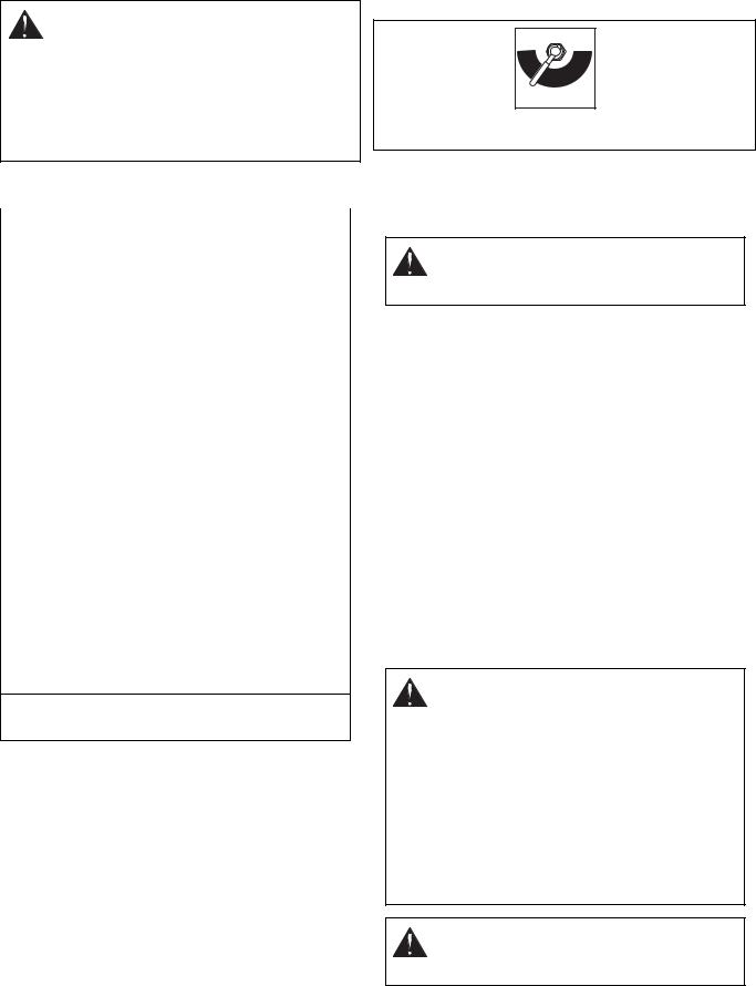
NOTE: To access the cooling system, fuel filter, oil drain petcock, and oil fill/dipstick, the seat must be tipped forward.
NOTE: To access the air filter, open the hood.
NOTE: Use Figure 4 to locate items called out in the maintenance schedule.
1
|
7 |
|
|
|
|
|
2 |
|
6 |
|
3 |
|
|
|
|
|
|
|
4 |
|
5 |
|
|
1. |
Cooling System |
4. |
Oil Filter |
2. |
Air filter (precleaner |
5. |
Spark Plug |
|
and cartridge) |
6. |
Oil Drain Petcock |
3. |
Fuel Filter |
7. |
Oil Fill/Dipstick |
Figure 4
Interval |
Task |
|
Action |
|
|
|
|
|
|
|
|
|
|
|
|
Check Safety Interlock |
WARNING: Safety interlock system failure and improper |
||
|
System |
operation of unit can result in death or serious injury. Test |
||
|
|
this system each time the unit is operated. If this system |
||
|
|
does not function as described, do not operate until repairs |
||
|
|
are made. |
||
|
|
|
|
|
|
Check Parking Brake |
Engage parking brake and engage transmission bypass |
||
|
|
lever. Push unit. If unit rolls, contact your Ariens/Gravely |
||
|
|
Dealer. |
||
|
|
|
|
|
Each Use |
Clean Unit |
Clean engine battery, seat, mower deck, etc. of all dirt and |
||
|
debris. Do not use solvents, hard cleaners, or abrasives. |
|||
|
|
|||
|
|
NOTE: Protect painted surfaces with automotive type wax. |
||
|
|
|
|
|
|
Check Tires |
See Specifications for correct tire pressure. |
||
|
|
|
|
|
|
Check Mower Blades |
Check for worn or damaged mower blades. |
||
|
|
|
|
|
|
Check Engine Oil |
Use oil fill/dipstick to check engine oil level. Add engine oil if |
||
|
|
needed, refer to Engine Manual for detailed instructions. |
||
|
|
|
|
|
|
Check Battery |
Keep battery and battery terminals clean. |
||
|
|
|
|
|
|
Lubricate Unit |
Apply grease to the two |
|
|
|
|
|||
|
|
front wheel zerks. |
|
|
|
|
|
Zerk |
|
25 Hours or Every Season |
|
|
|
|
|
|
|
OE0046 |
|
|
|
|
|
|
|
|
|
|
|
|
Clean Air Filter Precleaner1 |
Clean air filter precleaner. Refer to Engine Manual for |
||
|
|
detailed instructions. |
||
|
|
|
|
|
4 - 10

Interval |
Task |
Action |
|
|
|
|
|
|
|
|
|
|
Change Engine OIl2 |
Drain engine oil by opening oil drain petcock. Refer to |
|
|
|
Engine Manual for detailed instructions. |
|
|
|
|
|
|
Check Fasteners |
Check mower blade mounting hardware and all other |
|
50 Hours or Every Season |
|
fasteners. Replace fasteners that are missing or damaged. |
|
|
|
Tighten all nuts and bolts to the correct torque value. |
|
|
|
|
|
|
Inspect Muffler and Spark |
Replace muffler and (if equipped) spark arrestor if corroded. |
|
|
Arrestor |
Contact your Ariens/Gravely Dealer. |
|
|
|
|
|
|
Clean Air Filter Cartridge1 |
Clean air filter cartridge. Refer to Engine Manual for detailed |
|
|
|
instructions. |
|
|
|
|
|
|
Change Oil Filter |
Clean oil filter. Refer to Engine Manual for detailed |
|
|
|
instructions. |
|
|
|
|
|
|
Replace Spark Plug |
Replace spark plug. Refer to Engine Manual for detailed |
|
|
|
instructions. |
|
|
|
|
|
100 Hours or Every |
Replace Fuel Filter |
Replace fuel filter. Refer to Engine Manual for detailed |
|
|
instructions. |
||
Season |
|
|
|
Clean Cooling System1 |
Clean cooling system. Refer to Engine Manual for detailed |
||
|
|||
|
|
instructions. |
|
|
|
|
|
|
Check All Belts |
Replace worn or deteriorated belts. |
|
|
|
• Check hydrostatic belt (see Hydrostatic Belt |
|
|
|
Replacement). |
|
|
|
• Check PTO belt (see PTO Belt Replacement). |
|
|
|
|
|
|
Clean/Replace Spark Plugs |
Clean/replace spark plugs. Refer to Engine Manual for |
|
Yearly |
|
detailed instructions. |
|
|
|
||
|
Clean/Replace Fuel Filter |
Clean/replace fuel filter. Refer to Engine Manual for detailed |
|
|
|
instructions. |
|
|
|
|
1 Service more often when operating under heavy loads, high temperatures, or dusty conditions. Replace air filter precleaner and cartridge if very dirty.
2 Change after first 5 to 8 hours of use. Change every 25 hours when operating under heavy loads or in high temperatures.
4 - 11
4.4 REMOVE MOWER DECK
Remove (Figure 5)
1. Remove PTO belt from electric clutch.
NOTE: Perform step 2 and 3 for the right and left side of unit.
2.Remove guide arm from front mount bracket.
3.Remove rear lift link, rear trunnion, front lift link, and front trunnion from mower deck and mower lift.
4.Slide mower deck out from under unit.
Install (Figure 5)
1. Slide mower deck under unit.
NOTE: Perform step 2 and 3 for the right and left side of unit.
2.Install rear lift link, rear trunnion, front lift link, and front trunnion on mower deck and mower lift.
3.Install guide arm on front mount bracket.
4.Install PTO belt.
2 |
3 |
4 |
5 |
2 |
6 |
1
|
9 |
8 |
|
7 |
1. |
Mower Deck |
|
6. |
Front Mount Bracket |
2. |
Mower Lift |
|
7. |
Front Trunnion |
3. |
PTO Belt |
|
8. |
Rear Lift Link |
4. |
Guide Arm |
|
9. |
Rear Trunnion |
5. |
Front Lift Link |
|
|
|
Figure 5
4.5 LEVEL AND ADJUST PITCH OF MOWER DECK
Adjust on a level surface, with the tires inflated to the correct air pressure.
Level Mower Deck
1.Install adjustment pin in the fourth adjustment hole (Figure 6).
2.Rotate the right and left mower blades until the ends of both mower blades are facing rearward (Figure 7).
1
3 |
2 |
1. |
Adjustment Pin |
3. Fourth Adjustment |
2. |
Mower LIft Pedal |
Hole |
Figure 6
NOTE: The rear blade cutting height should be 2-7/8 to 3 in. (7.3 to 7.6 cm) from rear edge of mower blades to the ground on both blades.
IMPORTANT: The distance from rear edge of mower blades to the ground MUST NOT exceed 3 in. (7.6 cm) (Figure 7).
Mower Deck Shown From The Side
1 2
3
|
6 |
5 |
4 |
|
|
|
|
1. |
Mower Deck |
4. |
Front Blade Cutting |
2. |
Mower Blade(s) |
|
Height |
3. |
Front of Mower Deck |
5. |
Ground |
|
|
6. |
Rear Blade Cutting |
|
|
|
Height |
Figure 7 |
OA0010 |
|
3.Measure from rear edge of mower blades to the ground.
4.Perform steps 5 through 7 if the measurement is too high or too low on either side of mower deck.
5.Remove rear lift link and rear trunnion from mower deck and mower lift.
•TO RAISE the mower deck, turn rear trunnion clockwise several turns.
•TO LOWER the mower deck, turn rear trunnion counterclockwise several turns.
6.Install rear trunnion and rear lift link on mower deck and mower lift.
7.Check that the mower deck is level:
a. Rotate right and left mower blades to face side- to-side.
4 - 12
b. Measure outer edge of mower blades to ground. Measurement must be within 1/4 inch (6.35 mm).
•If mower deck is not level, repeat steps 5 and 6.
•If mower deck is level, record the distance from rear edge of mower blades to the ground and then adjust pitch of mower deck.
Adjust Pitch of Mower Deck
IMPORTANT: The mower blade end used to level the mower deck must be used to adjust the pitch of the mower deck.
1.Rotate the right and left mower blades 180 degrees until the end of the mower blade that was used to level the mower deck is facing forward (Figure 7).
NOTE: The front blade cutting height should be 1/16 - 1/4 in. (1.59 - 6.35 mm) lower than the rear blade cutting height (Figure 7).
2.Measure from front edge of right and left mower blades to the ground.
3.Subtract front blade cutting height measurement from rear blade cutting height measurement (Figure 7).
4.Perform steps 5 though 7 if the front blade cutting height is too high or too low on either side on either side of mower deck.
5.Remove front lift link and front trunnion from mower deck and mower lift (Figure 5).
•TO RAISE the mower deck, turn front trunnion clockwise several turns.
•TO LOWER the mower deck, turn front trunnion counterclockwise several turns.
6.Install front trunnion and front lift link on mower deck and mower lift.
7.Check mower deck pitch.
•If mower deck pitch is not correct, repeat steps 2 through 6.
•If mower deck pitch is correct, the adjustment is complete.
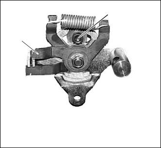
4.6 HYDROSTATIC TRANSMISSION NEUTRAL ADJUSTMENT
1.Shut off engine.
2.Position rear wheels off the ground. Be careful to secure the unit to the lift or position the unit to face a wall for safety. Disconnect the rods from the handlebars to the linkage.
3.Engage seat switch and start the engine. Disengage the parking brake. The drive wheels should not be rotating. If the wheels are not driven to rotate, proceed to Steering Control Neutral Adjustment.
To adjust the neutral setting for no wheel rotation:
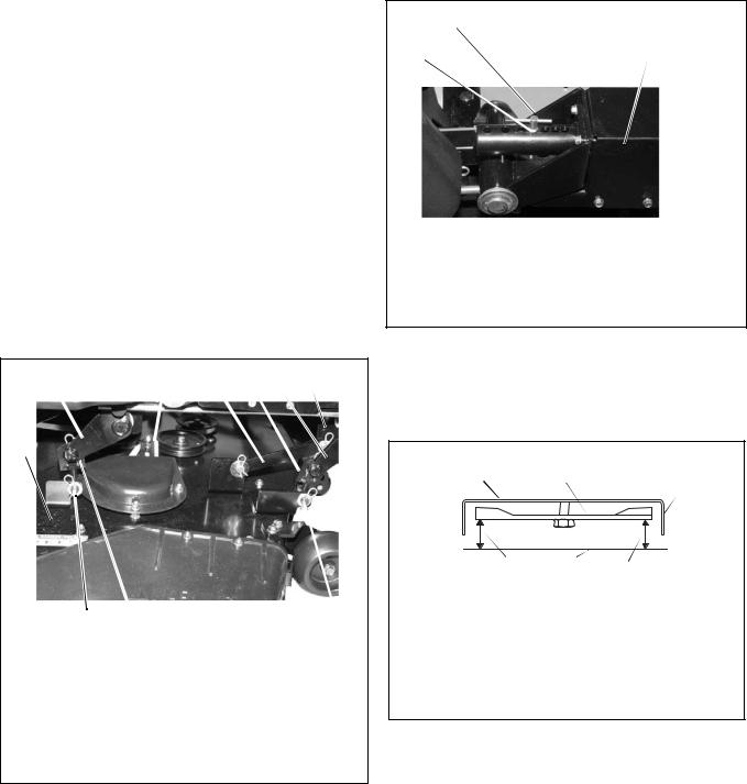
4.Use a hex wrench to loosen the locking bolt (Figure 8) until the linkage can be rotated by hand.
5.With the engine running and the drive wheels off the ground, rotate the linkage in either direction. The correct linkage position is obtained when the wheel is not being driven (under power).
6.Hold the linkage in place and tighten the locking bolt.
7.Shut off engine and reconnect steering rods.
8.Check parking brake linkage for proper movement.
1
4 
3
|
2 |
|
|
1. |
Locking Bolt |
3. |
Forward Arm |
2. |
Reverse Arm |
4. |
Return Spring |
Figure 8
4.7 ADJUSTING UNIT TO TRACK STRAIGHT
Tires must be inflated to specifications, drive units should be adjusted for neutral.
NOTE: Before making the following adjustments; check the dampener on each of the steering handles. It is possible that the fixed position of the dampener is limiting the travel of the steering arm. To adjust the dampener arm; loosen the dampener anchor nut to allow movement. Tighten when done.
1.Start engine and warm up hydraulics.
2.Operate the unit and position it with adequate running space.
3.Push both handles to full forward. The unit should travel in a straight line. If the unit steers to one side, adjustment is needed. Make note of which way the unit is turning. Adjustment will be made to the drive unit on the opposite side off the direction of the turn. This is the faster wheel.
4.Loosen the jam nuts on the transaxle rod.
5.Screw the nyloc jam nut further down one or two turns (depending on the amount of turning that needs correction).
4 - 13
Loading...