


 Loading...
Vertigo XG
Advanced HD/SD Graphics Processor
Configuration Guide
M848-9302-500

Copyright & Trademark Notice
Copyright © 2015, Grass Valley USA, LLC. All rights reserved.
Belden, Belden Sending All The Right Signals, and the Belden logo are trademarks or registered trademarks of Belden Inc. or its affiliated companies in the United States and other jurisdictions. Grass Valley USA, LLC, Miranda, Vertigo Suite, Vertigo XG and Xmedia Server are trademarks or registered trademarks of Grass Valley USA, LLC. Belden Inc., Grass Valley USA, LLC, and other parties may also have trademark rights in other terms used herein.
Terms and Conditions
Please read the following terms and conditions carefully. By using the Vertigo XG documentation, you agree to the following terms and conditions.
Grass Valley hereby grants permission and license to owners of the Vertigo XG to use their product manuals for their own internal business use. Manuals for Grass Valley, A Belden Brand products may not be reproduced or transmitted in any form or by any means, electronic or mechanical, including photocopying and recording, for any purpose unless specifically authorized in writing by Grass Valley.
A Grass Valley manual may have been revised to reflect changes made to the product during its manufacturing life. Thus, different versions of a manual may exist for any given product. Care should be taken to ensure that one obtains the proper manual version for a specific product serial number.
Information in this document is subject to change without notice and does not represent a commitment on the part of Grass Valley.
Warranty Policies
Warranty information is available in the Support section of the Grass Valley Web site (www.grassvalley.com).
Document Identification
Title |
Vertigo XG Configuration Guide |
|
|
Part number |
M848-9302-500 |
|
|
SW version |
Vertigo Suite v5.0 |
|
|

Revision History
After the original release date, this document may be updated with edits and then rereleased. The following table tracks the versions of this document.
Revision date |
Description |
|
|
November 28, 2014 |
Original release |
|
|
March 02, 2015 |
Vertigo Suite v5.0 SP1 release |
|
|

TABLE OF CONTENTS
Introduction.......................................................................................................................... |
1-1 |
Vertigo XG’s standard and optional features..................................................................................... |
1-2 |
Vertigo XG system integration........................................................................................................... |
1-4 |
Vertigo XG downstream and simulcast branding models .................................................................. |
1-5 |
Overview of the Vertigo XG’s Hardware ............................................................................ |
2-1 |
The Vertigo XG’s front panel components......................................................................................... |
2-2 |
The Vertigo XG’s rear panel components.......................................................................................... |
2-4 |
Vertigo XG signal path and rendering processes .............................................................................. |
2-9 |
Video input/output channels ....................................................................................................... |
2-10 |
Audio input/output channels ....................................................................................................... |
2-11 |
Ancillary data processing............................................................................................................ |
2-12 |
Graphics processing ................................................................................................................... |
2-12 |
Clip Player and media storage.................................................................................................... |
2-13 |
Vertigo XG’s Desktop Applications & Tools |
...................................................................... 3-1 |
Vertigo XG’s desktop - device identification ...................................................................................... |
3-2 |
Vertigo XG Control Panel and XG Dashboard................................................................................... |
3-3 |
Xplay - Playout control application..................................................................................................... |
3-5 |
Device Manager............................................................................................................................ |
3-6 |
Automation Configuration ............................................................................................................. |
3-8 |
Xplay’s Automation settings.......................................................................................................... |
3-9 |
Vertigo Command Shell................................................................................................................... |
3-10 |
Windows Explorer............................................................................................................................ |
3-12 |
Embedded Xmedia Server Control Panel................................................................................... |
3-13 |
XPublish Agent Control Panel .................................................................................................... |
3-15 |
Data Server Control Panel.......................................................................................................... |
3-16 |
Vertigo XG Portal - Vertigo XG’s Remote Configuration Tool |
.......................................... 4-1 |
Accessing and logging into the Vertigo XG Portal............................................................................. |
4-2 |
Overview of the Vertigo XG Portal’s menu commands...................................................................... |
4-4 |
Remotely shutting down the Vertigo XG device ................................................................................ |
4-6 |
Restarting the Vertigo XG device remotely........................................................................................ |
4-7 |
Viewing the processes running on the Vertigo XG device................................................................. |
4-8 |
Configuring Vertigo XG’s network settings ........................................................................................ |
4-9 |
Specifying the Vertigo XG device’s hostname................................................................................. |
4-11 |
Specifying the Vertigo XG device’s Date & Time settings ............................................................... |
4-12 |
Logging off of the Vertigo XG Portal................................................................................................ |
4-13 |
Dashboard - Vertigo XG’s Local Configuration Software................................................. |
5-1 |
About the Dashboard......................................................................................................................... |
5-3 |
Starting Dashboard............................................................................................................................ |
5-4 |
An overview of the Dashboard’s interface components..................................................................... |
5-5 |
Dashboard’s menus and buttons....................................................................................................... |
5-6 |
Device List ......................................................................................................................................... |
5-8 |
Vertigo XG Configuration Guide |
TOC-1 |

Table of Contents
Loading and refreshing the device list ........................................................................................... |
5-9 |
Saving the device list ..................................................................................................................... |
5-9 |
Restarting a device in the device list ........................................................................................... |
5-10 |
Monitoring the status of a device ................................................................................................. |
5-10 |
Removing a device from the device list ....................................................................................... |
5-10 |
Device Discovery Tool...................................................................................................................... |
5-11 |
Performing a Manual Device Discovery....................................................................................... |
5-13 |
Performing an Automatic Device Discovery ................................................................................ |
5-14 |
Device Profile page .......................................................................................................................... |
5-15 |
Device Settings tabs and configuration pages ................................................................................. |
5-17 |
Device settings buttons................................................................................................................ |
5-18 |
General page ............................................................................................................................... |
5-19 |
Resolution page........................................................................................................................... |
5-21 |
Live Window page ....................................................................................................................... |
5-23 |
Clips page.................................................................................................................................... |
5-25 |
3D Engine page ........................................................................................................................... |
5-27 |
Logging page ............................................................................................................................... |
5-29 |
Hardware Settings > Genlock page ............................................................................................. |
5-31 |
Hardware Settings > Video page ................................................................................................. |
5-34 |
Hardware Settings > Audio page ................................................................................................. |
5-36 |
Hardware Settings > Ancillary page............................................................................................. |
5-38 |
Hardware Settings > Watch Dog page ........................................................................................ |
5-41 |
Licensing page............................................................................................................................. |
5-42 |
Audio Mixing Profiles dialog box....................................................................................................... |
5-43 |
TOC-2 |
Vertigo XG Configuration Guide |
1 INTRODUCTION
The Vertigo XG is a full-featured HD/SD graphics processor that provides high performance single or dual channel graphics rendering and video playback performance. The Vertigo XG is ideal for a wide range of advanced real-time broadcast applications, like HD/SD dualcasting with independent graphics for HD and SD, and single channel applications demanding sophisticated, multi-channel branding and promotional graphics.
The main purpose of this Configuration Guide is to provide practical reference and procedural information on how to use the Vertigo XG’s desktop and remote configuration applications to configure the Vertigo XG graphics processing system.
The following sections of this configuration guide describe the Vertigo XG’s features, capabilities, and system integration:
•“Vertigo XG’s standard and optional features” on page 1-2
•“Vertigo XG system integration” on page 1-4
•“Simulcast downstream branding using the Vertigo XG” on page 1-6
Further chapters provide descriptions of the Vertigo XG’s hardware and software components:
•“Overview of the Vertigo XG’s Hardware” on page 2-1
•“Vertigo XG’s Desktop Applications & Tools” on page 3-1
Most Vertigo XG devices are installed and configured by qualified network administrators or Grass Valley’s Integration Specialists using the Vertigo XG Portal and Dashboard software interfaces. While we do not recommend that users change the Vertigo XG’s settings, the following chapters provide detailed descriptions of each of the Vertigo XG settings:
•“Vertigo XG Portal - Vertigo XG’s Remote Configuration Tool” on page 4-1
•“Dashboard - Vertigo XG’s Local Configuration Software” on page 5-1
Vertigo XG Configuration Guide |
1-1 |
Introduction
Vertigo XG’s standard and optional features
The Vertigo XG is available in two (2) standard models:
VX-Vertigo-XG21-e Vertigo XG single channel graphics engine (2 inputs, 1 output) used for downstream branding (see page 1-5).
VX-Vertigo-XG22-e Vertigo XG dual channel graphics engine (2 inputs, 2 outputs) used for downstream simulcast branding (see page 1-5).
Both models of the Vertigo XG have the following features and capabilities:
•3 RU rack mount chassis
•2 video input channels
•1 video output channel (XG21-e) or 2 video output channels (XG22-e)
•SD and HD video support
•1 TB of video and audio storage, which is expandable to 2 TB
•16 embedded audio channels per SDI stream
•Discrete AES audio channels - up to 8 in and 16 out (XG21-e) or 2 x 16 out (XG22-e)
•Independent DVEs on each video input
•Tri-mode hardware Video bypasses
•VAnc + VBI extraction processing and insertion or VAnc/VBI pass through
•Unlimited virtual layers that can be controlled independently
•Real-time control of live data sources with automatic on-air updates
•True Type/Unicode character support
•One seat of Xplay is included with each channel of the Vertigo XG purchased which integrates the following features and functionality:
•Automation interface via RS-232, RS-422 (option) and TCP/IP
•Xplay’s graphical interface used for manual control of playlists
•“As run” logging
1-2 |
Vertigo XG Configuration Guide |

Introduction
The following options are available to both models of the Vertigo XG:
VX-RS422-2-e |
2 port RS-422 card |
|
The RS-422 card provides an interface upon which the Vertigo XG can |
|
communicate with automation systems. See “RS-422 Connectors” on |
|
page 2-6 for more information. |
VX-Audio-e |
Audio processor |
|
The Audio option allows you play out audio clips and voice-over tracks. |
|
See “Audio input/output channels” on page 2-11 for more information. |
|
|
VX-EAS |
EAS Text Integration (EAS Plugin and EAS Software Panel) |
|
High quality EAS text and audio can be played out with the Vertigo XG |
|
processor, using templates which integrate channel branding graphics |
|
for a consistent on-air presentation. |
|
|
VX-GPI-8-e |
GPI card |
|
The GPI card allows for control of the Vertigo XG via GPI triggers. The |
|
card allows for up to 8 GPI in and 8 GPI out. See “GPI Card Connector” |
|
on page 2-8 for more information about the GPI card option. |
|
|
VX-TC-e |
Time Code card |
|
The Time Code card allows you to lock the Vertigo XG’s system clock to |
|
an external timecode. See “Time Code Card” on page 2-6 for more |
|
information about the Time Code option. |
|
|
VX-ClipPlayer |
Clip Player |
|
The Clip Player is an internal codec package for playing out multi-format |
|
video clips. See “Clip Player and media storage” on page 2-13 for more |
|
information about the Clip Player option. |
|
|
VX-2TB-UPG |
1 TB RAID10 Expansion option (2 x 1TB) |
|
Increases the usable storage from 1TB to 2TB. See “Clip Player and |
|
media storage” on page 2-13 for more information. |
Vertigo XG Configuration Guide |
1-3 |
Introduction
Vertigo XG system integration
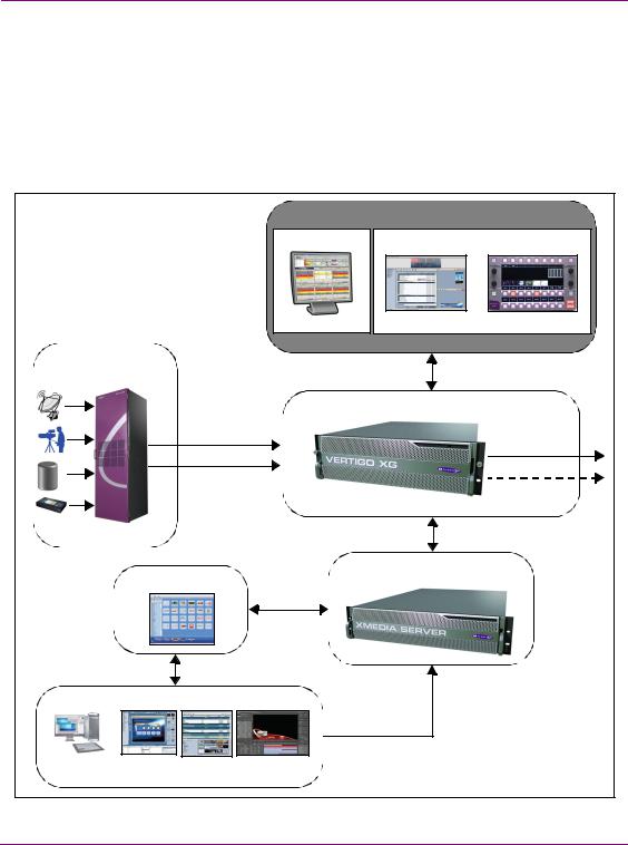
Vertigo XG devices can be fully integrated with other system components to provide a complete branding and playout solution. Figure 1-1 demonstrates that in a downstream branding model, video and audio content can be brought into the Vertigo XG from a variety of sources, while the graphics content is created and managed using the Vertigo Suite and Xmedia Server. Vertigo XG devices can be fully controlled by third-party automation systems, or manually controlled using Xplay, a Branding Panel or the Xpanel software application.
|
|
|
|
Master Control |
|
|
|
|
Automation controlled |
Manual/Operator Controlled |
|
|
|
|
3rd party Automation |
Xplay |
RCP-BR |
Program Video Input |
|
|
|
|
|
|
|
|
Graphics Branding & Playout |
||
|
|
HD/SD SDI |
|
|
|
|
|
HD/SD SDI |
|
HD/SD SDI |
|
|
|
|
|
||
Video & Audio |
|
|
|
|
|
Router |
|
|
|
|
|
|
Media Management |
Centralized Asset Management |
|||
|
|
|
|
||
|
Graphics Preparation |
|
|
||
Photoshop, Premiere |
Xstudio |
Xbuilder |
After Effects Plug-in |
|
|
or Final Cut |
|
|
|
|
|
Figure 1-1. Vertigo XG device branding and playout system integration
1-4 |
Vertigo XG Configuration Guide |

Introduction
Vertigo XG downstream and simulcast branding models
The Vertigo XG device can be used for single or dual channel downstream branding, which allows for graphics inserts, downstream of video server or master control.
Figure 1-2 demonstrates a typical dual channel downstream branding setup, in which graphics insertion occurs downstream of master control.
Branding and Playout
- DVEs |
Branded program on |
- Video clips |
output channel A |
- Audio clips |
|
- Multi-layer CG |
|
- Multi-layer graphics |
|
HD/SD SDI
HD/SD SDI
Master Control
Switchers
Branded program on
Video & Audio output channel B
Router
Figure 1-2. Downstream branding on two channels using the Vertigo XG
Figure 1-3 demonstrates the types of downstream branding graphics that can be achieved using the Vertigo XG.
Coming next snipe with clip |
|
Schedule board with clips |
|
|
|
|
|
|
Tickers and score overlays |
Junctions with live-squeeze backs and clips |
Figure 1-3. Examples of rich downstream branding using the Vertigo XG
Vertigo XG Configuration Guide |
1-5 |
Introduction
Figure 1-4 demonstrates that the Vertigo XG supports the “pairing” of dual rendering engines for simulcast applications. Using a signal control point to drive an HD and an SD stream with independent graphics and branding, the Vertigo XG can playout graphics that are optimized for HD and SD on each output channel.
Branded HD Program
HD Input |
HD Program |
Down
Converter
SD Input |
SD Program |
Branded Down-converted
SD Program
Figure 1-4. Simulcast downstream branding using the Vertigo XG
1-6 |
Vertigo XG Configuration Guide |
2 OVERVIEW OF THE VERTIGO XG’S
HARDWARE
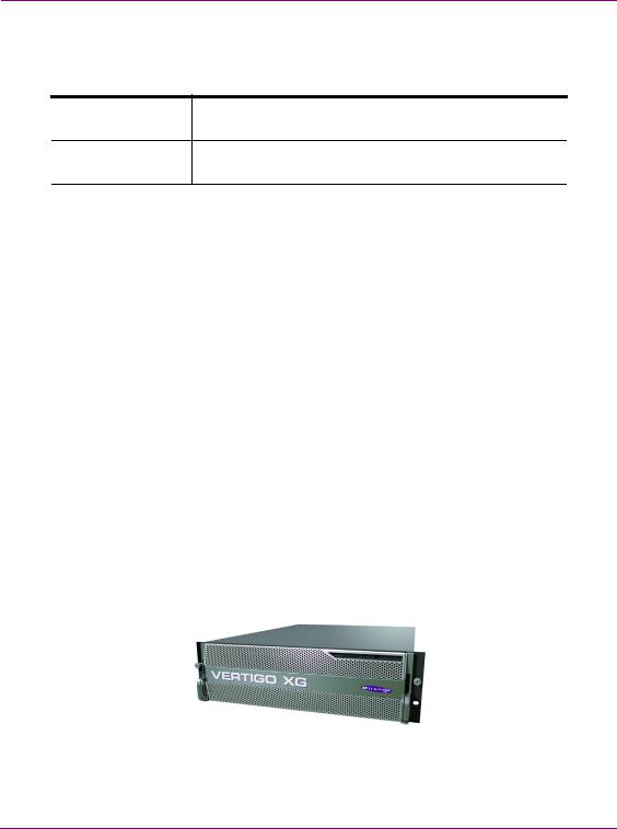
Physically, the Vertigo XG is a 3RU rackmount rendering platform that incorporates redundant fans, three power supplies, and 1 TB RAID1-enabled storage (optional 2 TB RAID10 expansion).
The Vertigo XG features easy frontal access to the SCSI drives and a control panel featuring LEDs and buttons for system monitoring and operation (see page 2-2 for more details). The rear panel also provides convenient access to two power supply modules, six PCI expansion slots which contain the video, audio, and graphics cards, and various I/O ports (USB, COM1, VGA, Ethernet...etc). See page 2-4 for more details about the Vertigo XG’s rear panel components and connectors.
The following hardware options are also available to enhance the performance and capabilities of the Vertigo XG:
•VX-RS422-e (2 port RS-422/485 card)
•VX-Audio-e (Discrete audio)
•VX-GPI-8-e (GPI card)
•VX-TC-e (Time Code card)
•VX-2TB-UPG (2 TB RAID10 expansion drive)
Chassis |
FORM: 3U rackmount chassis |
|
HEIGHT: 5.2” (132 mm) |
|
WIDTH: 17.7” (450 mm) |
|
DEPTH: 25.5” (648 mm) |
|
|
Power consumption |
AC input: 100 - 240V, 50 - 60 Hz |
|
Consumption: 4.05 - 1.73A |
|
Power: 410 max. |
|
|
Vertigo XG Configuration Guide |
2-1 |
Overview of the Vertigo XG’s Hardware
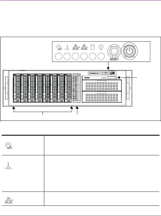
The Vertigo XG’s front panel components
The Vertigo XG’s front panel features convenient access to the hard drives, a CD/DVD ROM drive, and a control panel containing six LEDs and two buttons for system monitoring and operation. The table following the figure 2-1 describes the function of each LED and button.
|
POWER |
|
CD/DVD ROM Drive |
Hard Drives |
Floppy |
|
Drive |
Figure 2-1. The Vertigo XG’s front panel components
POWER FAILURE |
Indicates a power supply module has failed, which is accompanied by an |
|
audible alarm. A backup power supply module will take the load and keep |
|
the system running, but the failed module will need to be replaced. This |
|
red LED should be off when the system is operating normally. |
OVERHEAT / FAN FAIL When this red LED flashes, it indicates a fan failure. When it is constantly illuminated (solid on), it indicates an overheat condition, which may be caused by cables obstructing the airflow in the system or the ambient room temperature being too warm. Check the routing of cables and make sure that all fans are present and operating normally. You should also check to make sure that the chassis covers are installed properly. Finally, verify that the heatsinks are installed properly. This LED will remain flashing or on as long as the above mentioned conditions exist.
LAN2 |
A flashing green LAN2 LED indicates network activity on LAN2. |
2-2 |
Vertigo XG Configuration Guide |

|
|
Overview of the Vertigo XG’s Hardware |
|
|
|
|
|
|
LAN1 |
A flashing green LAN1 LED indicates network activity on LAN2. |
|
|
|
|
|
|
HDD ACTIVITY |
This flashing amber LED indicates IDE channel activity. |
|
|
|
|
|
|
POWER INDICATOR (LED) |
Indicates that power is being supplied to the system’s power supply units. |
|
|
|
This green LED should normally be illuminated when the system is in |
|
|
|
operation. |
|
|
|
|
|
|
RESET |
The Reset button reboots the system. |
|
|
|
|
|
|
POWER BUTTON |
This is the main power button, which is used to apply or turn off the main |
|
|
|
system power. Turning off this button removes the main power, but keeps |
|
|
|
standby power supplied to the system. |
|
|
|
|
|
Vertigo XG Configuration Guide |
2-3 |
Overview of the Vertigo XG’s Hardware
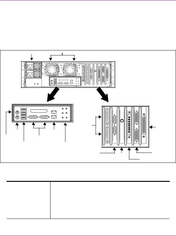
The Vertigo XG’s rear panel components
The Vertigo XG’s rear panel features convenient access to the video card’s I/O connector, which provides 4 SD/HD SDI video outputs, a reference signal input, and AES audio input/output. The rear panel also provides access to the graphics card connector, as well as various I/O ports (RS-422, USB, Ethernet...etc.).
The table following the figure 2-2 describes the function of each connector on the rear panel of the Vertigo XG chassis.
|
|
Power Supply Modules (2) |
System Fans (2) |
|
|
|
|
LTC |
|
|
|
|
IN |
|
|
|
|
LTC |
|
|
|
|
IN |
|
|
|
|
Graphics Card |
GPI Card Connector |
|
|
|
Connectors (2) |
(option) |
|
Keyboard |
Network Ethernet |
|
|
|
Connector |
Connectors (2) |
|
|
Mouse |
|
Serial |
|
|
Connector |
|
|
||
RS-232 Ports (2) |
|
|||
|
|
|
||
|
|
USB 2.0 |
Audio I/O Ports |
|
|
|
Connectors (4) |
(Disabled) |
|
|
|
|
RS-422 Connectors |
Discrete Audio |
|
|
|
(option) |
Connectors (2) |
|
|
|
Time Code |
(option) |
|
|
|
Card |
SDI Video Card |
|
|
|
|
I/O Connector |
Figure 2-2. The Vertigo XG’s rear panel components
Mouse & Keyboard The two (2) PS/2 connectors on the rear panel allow you to connect a connectors mouse and keyboard to the Vertigo XG device. These peripherals are required during the device’s initial configuration, which involves using
the Vertigo XG’s desktop applications, including Dashboard.
Note that if the mouse or keyboard has a UBS connector, you can connect them to the USB 2.0 connectors on the front or rear panels of the Vertigo XG device.
2-4 |
Vertigo XG Configuration Guide |
Overview of the Vertigo XG’s Hardware
USB 2.0 Connectors The four (4) USB 2.0 connectors on the rear panel allow you to connect peripheral devices (e.g. keyboard, mouse, flash drive...etc) to the Vertigo XG.
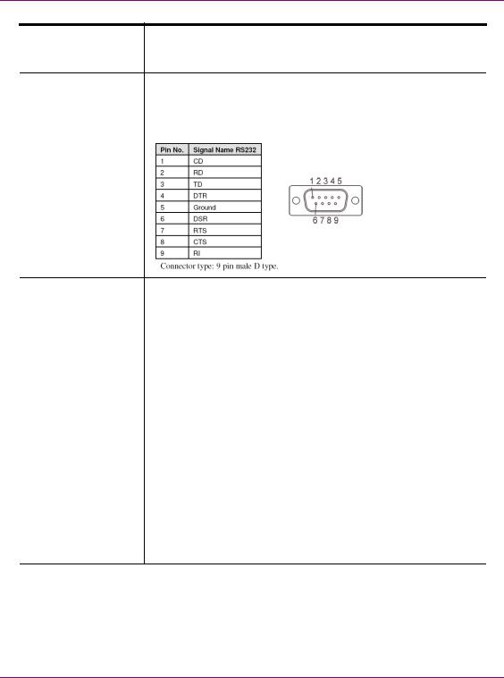
Serial RS-232 Port The two (2) RS-232 connectors provide two control ports upon which the automation system’s serial cables are connected. It is through this connection that the automation system communicates and controls the Vertigo XG using automation protocol commands.
Network Ethernet |
The two (2) Network Ethernet connectors are teamed and allow you to |
Connectors |
connect the Vertigo XG device to the Local Area Network (LAN). |
|
NIC Teaming is a networking concept where multiple network |
|
adapters within a computer are combined in parallel to provide |
|
redundancy for the network interface. On an Vertigo XG device, the |
|
two Local Area Connection network adapters are teamed together |
|
(connect 2 cables to the 2 NIC cards at the same time) to form a third |
|
virtual adapter. In the event of an adapter, cable or switch failure, the |
|
network interface fails over to the healthy adapter. |
|
When the individual Local Area Network adapters are teamed |
|
together the individual Local Area Network adapters are not |
|
accessible or configurable. Only the teamed virtual adapter can be |
|
configured. |
|
If you only have 1 cable connected, then the teaming will still be in |
|
effect but all traffic will be over that one cable. If that NIC fail, you will |
|
have to manually move the cable to the other NIC. |
|
|
Audio I/O ports |
These six (6) audio I/O ports are not supported by the Vertigo XG since |
|
external audio input and output is provided by the Discrete EAS option |
|
(see “Audio input/output channels” on page 2-11). |
Vertigo XG Configuration Guide |
2-5 |
Overview of the Vertigo XG’s Hardware
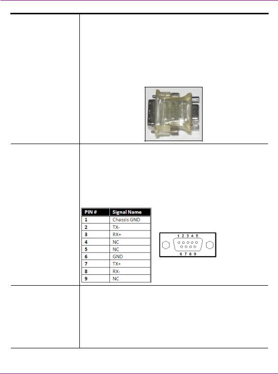
Graphics Card’s DVI The graphics card’s DVI connectors allow you to connect the Connectors Vertigo XG device to DVI monitor. The monitor is only required during
the device’s initial configuration, so as to display Vertigo XG’s desktop applications, including XG Dashboard.
Note that although there are two (2) DVI connectors, the Vertigo XG can display to only one monitor. Therefore, it does matter which of the two connectors the monitor’s cable is connected to.
Use the adapter (below) if you would rather connect a VGA monitor.
RS-422 Connectors |
Vertigo XG hardware option: Vx-RS422-e |
|
The RS-422 connectors provide two control ports upon which the |
|
automation system’s serial cables are connected. It is through this |
|
connection that the automation system communicates and controls |
|
the Vertigo XG using automation protocol commands. |
|
The following represents the pinout assignments of the RS-422 |
|
connector: |
Time Code Card |
Time Code Card option: VX-TC-e |
|
The Time Code card allows you to lock the Vertigo XG’s system clock |
|
to an external timecode. The Time Code card reads Longitudinal Time |
|
Code (LTC) from the signal present at the BNC connector. |
|
The Time Code option ensures an accurate time stamp for system |
|
logs. Accurate time is also required for time-based on-air graphics (i.e. |
|
countdown clocks). |
2-6 |
Vertigo XG Configuration Guide |
Overview of the Vertigo XG’s Hardware
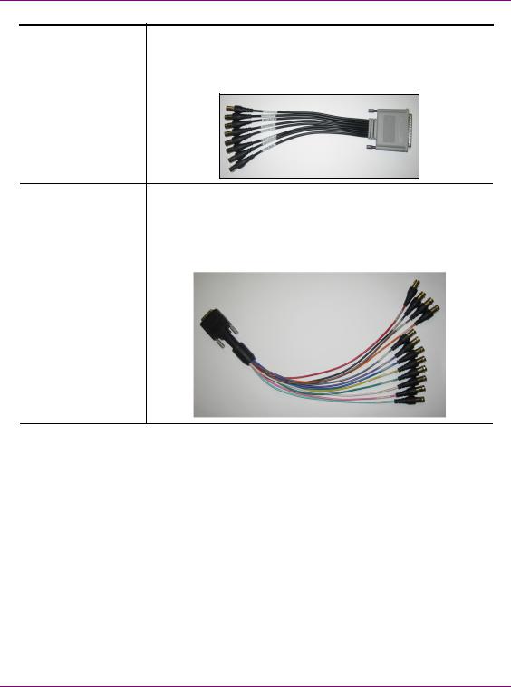
SDI Video Card I/O A breakout cable is used to connect the Video Card I/O connectors to Connector the SDI video input/output cables and the reference I/O. See “Video
input/output channels” on page 2-10 for more information about the Vertigo XG’s video input/output channel connections.
Discrete Audio |
Vertigo XG hardware option: Vx-Audio-e |
||
connectors |
A breakout cable is used to connect the optional discrete audio card |
||
|
|||
|
I/O connectors to the BNC audio input/output cables. See “Audio |
||
|
input/output channels” on page 2-11 for more information about the |
||
|
Vertigo XG’s discrete audio input/output channel connections. |
||
|
|
|
|
|
|
|
|
Vertigo XG Configuration Guide |
2-7 |
Overview of the Vertigo XG’s Hardware
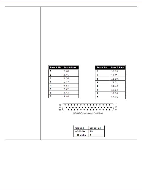
GPI Card Connector |
Vertigo XG hardware option: Vx-GPI-8-e |
|||||
|
The GPI card allows for control of the Vertigo XG via GPI triggers. The |
|||||
|
card provides for up to 8 optically isolated GPI inputs and 8 reed relay |
|||||
|
GPI outputs. |
|
|
|
||
|
Port A is an 8 bit input port connected to optically isolated inputs |
|||||
|
sensors. Each sensor can be used to interface a voltage and then |
|||||
|
sense whether the voltage is on or off. |
|||||
|
The reed relays are well suited for low current applications. The relays |
|||||
|
are normally open, and will close when energized. |
|||||
|
The following tables identify the pinout assignment for the GPI card’s |
|||||
|
input and output ports: |
|
|
|
||
|
Input Ports Pin Assignment |
Output Ports Pin Assignment |
||||
|
|
|
|
|
|
|
|
|
|
|
|
|
|
|
|
|
|
|
|
|
Power and Ground Pin Assignments
2-8 |
Vertigo XG Configuration Guide |
Overview of the Vertigo XG’s Hardware
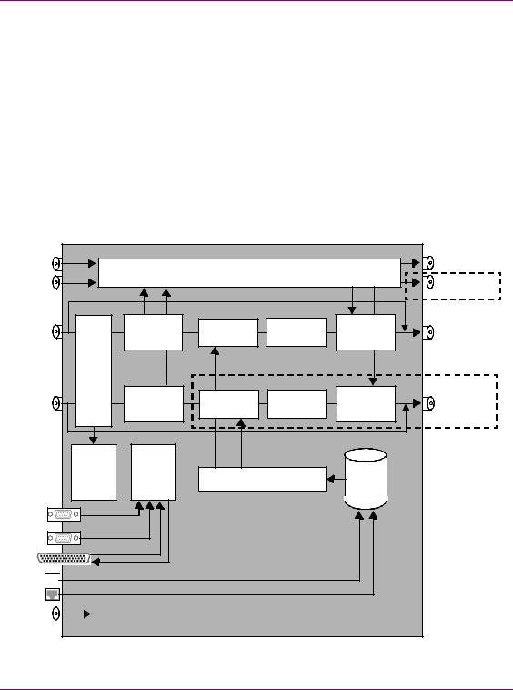
Vertigo XG signal path and rendering processes
The Vertigo XG HD/SD graphics processor block diagram (figure 2-3) demonstrates that the audio and video signals are brought into the Vertigo XG hardware, exposed to various processing options, and then rendered for output.
To help you make more informed configuration decisions, the following sections describe the signal path and processing options that performed by the Vertigo XG hardware and software drivers.
•“Video input/output channels” on page 2-10
•“Audio input/output channels” on page 2-11
•“Ancillary data processing” on page 2-12
•“Graphics processing” on page 2-12
•“Clip Player and media storage” on page 2-13
AES IN A |
|
AES OUT A |
|
(ch. 1-4) |
Audio Mixer & Processor |
(channels 1-16) |
|
AES IN B |
AES OUT B |
||
|
|||
(ch. 5-8) |
|
(channels 1-16) |
|
|
Relay Bypass A |
XG-22-e model only |
|
|
|
SD/HD Channel 1 |
|
|
|
|
|
Input A |
Audio |
Rendering A |
Compositor |
Audio |
SD/HD Channel 1 |
|
De-embedder |
DVE & Keyer |
Embedder |
Output A |
|
|
|
Virtual |
|
Input |
|
Switch |
XG-22-e model only |
SD/HD Channel 2 |
|
|
|
|
|
Input B |
Audio |
Rendering B |
Compositor |
Audio |
SD/HD Channel 2 |
|
De-embedder |
DVE & Keyer |
Embedder |
Output B |
|
|
|
|
Relay Bypass B |
|
Ancillary |
|
|
Data |
Controller |
Media |
Processing |
Clip Player |
|
|
|
Storage |
RS-232 |
RS-422
(Optional)
GPI-8 I/O
(Optional)
GigE Media 
Import
REF IN |
|
|
|
|
Genlock |
|
|
|
|
||
|
|
|
|||
|
|
|
|
|
|
Figure 2-3. Block diagram of the dual channel Vertigo XG (VX-Vertigo-XG22-e)
Vertigo XG Configuration Guide |
2-9 |
Overview of the Vertigo XG’s Hardware
Video input/output channels
Depending on the model, Vertigo XG devices offer two (2) video SD/HD input channels with one (1) or two (2) video SD/HD output channels. Figure 2-4 and the following table identifies and describes the Vertigo XG video card’s input and output connections, including the hardware bypass.
LTC
IN
|
SDI IN A |
|
|
|
|
|
|
|
|
|
|
|
|
|
SDI IN B |
|
|
|
|
|
|
|
|
|
|
|
|
|
ANALOG REF IN |
|
|
|
|
|
|
|
|
|
|
||
|
ANALOG REF LOOP OUT |
|
|
|||
|
|
|
||||
|
SDI OUT A (Fill 1) |
|
|
|||
|
|
|
||||
|
SDI OUT B (Fill 2) |
|
|
|||
|
|
|
||||
|
SDI OUT C / KEY |
|
|
|||
|
|
|
||||
Video breakout cable |
SDI OUT D / KEY |
|
|
|
||
|
|
|||||
H/W Bypass
Channel 1
H/W Bypass
Channel 2
Figure 2-4. The Vertigo XG video card’s input and output connections
Pin/Channel Name |
Description |
|
|
SDI IN A |
SDI IN A is the primary input channel connection. |
|
|
SDI IN B |
SDI IN B can act as a separate input channel. |
|
|
ANALOG REF IN |
Analog Ref In is the input reference signal used by the Genlock hardware to |
|
synchronize the phase timing video and graphics processing. |
|
|
ANALOG REF |
Analog Ref Out loops the signal that comes in through the Analog Ref In |
LOOP OUT |
channel. |
|
|
SDI OUT A |
SDI OUT A (Fill 1) is the primary output channel connection. |
|
|
SDI OUT B |
SDI OUT B (Fill 2) is the second output channel in a dual-channel configuration. |
|
No signal is present at this connection for single-channel configurations. |
|
|
SDI OUT C / KEY |
SDI OUT C is the matching Key channel for SDI OUT A. |
|
|
SDI OUT D / KEY |
SDI OUT D is the matching Key channel for SDI OUT B. |
|
No signal is present at this connection for single-channel configurations. |
|
|
2-10 |
Vertigo XG Configuration Guide |
Overview of the Vertigo XG’s Hardware
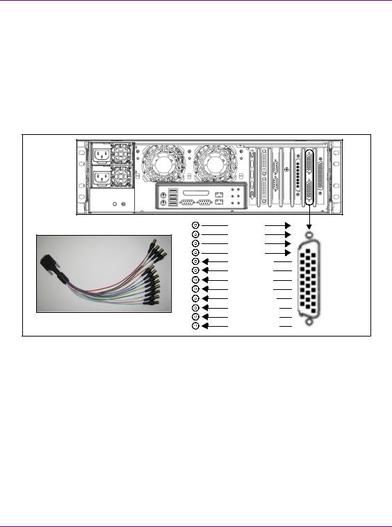
Audio input/output channels
The Vertigo XG supports both embedded and discrete audio channels. Each video input/output can contain up to 8 stereo pairs (16 channels) of embedded audio.
The number of discrete audio input/output channels depends on the number of physical inputs available. For each physical input available there will be a discrete audio breakout cable (see figure 2-5). Each discrete audio breakout cable contains 4 BNC inputs and
8 BNC outputs. Each BNC connector represents 1 stereo pair (2 channels) of digital AES/EBU audio. Therefore, each discrete audio breakout cable contains 4 stereo pairs (8 channels) of input and 8 stereo pairs (16 channels) of output.
|
LTC |
|
|
IN |
|
|
AES IN 1/2 |
|
|
AES IN 3/4 |
|
|
AES IN 5/6 |
|
|
AES IN 7/8 |
|
|
AES OUT 1/2 |
|
|
AES OUT 3/4 |
|
|
AES OUT 5/6 |
|
|
AES OUT 7/8 |
|
|
AES OUT 9/10 |
|
|
AES OUT 11/12 |
|
Discrete audio breakout cable |
AES OUT 13/14 |
|
AES OUT 15/16 |
||
|
Figure 2-5. Vertigo XG’s discrete audio channels
When capturing audio, the Vertigo XG can capture embedded and discrete simultaneously, however there are restrictions. The stereo pair cannot be captured from both sources at the same time. For example, if only capturing pairs 1 & 2 from embedded, then pairs 1 & 2 are not available from AES, but 3-8 are available.
The Vertigo XG performs one-to-one passthrough of audio. All captured audio will be broadcast on the corresponding outputs. For example, if the first 2 stereo pairs of embedded audio on SDI IN A are captured, then the signal will be output as the first 2 stereo pairs of embedded audio on SDI OUT A and simultaneously on AES discrete outputs 1 & 2.
Vertigo XG Configuration Guide |
2-11 |
Overview of the Vertigo XG’s Hardware
Ancillary data processing
The Vertigo XG reserves some hardware functionality for the extraction, processing, and insertion of ancillary data into the output video signal, for example, Vertical Ancillary (VAnc) data and Vertical Blanking Interval (VBI) data.
The ancillary data space can be used as a transport mechanism for data to be extracted by the Vertigo XG for triggering keyers, squeezes (DVEs) or other graphics events. Metadata embedded upstream of the Vertigo XG is extracted and processed by the control application to control these actions.
Graphics processing
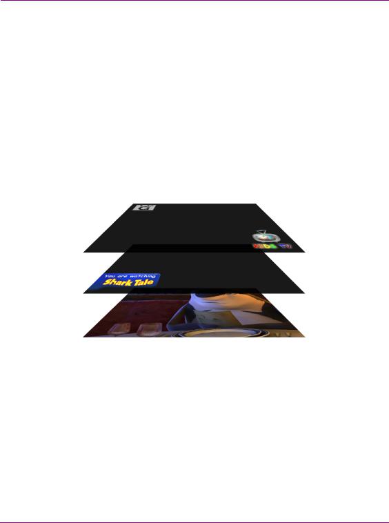
The Vertigo XG is a multi-layered graphics engine that supports loading of multiple graphics scenes on independently-controlled, dynamic layers. The number of layers to be controlled is defined in the control application (Xplay, Xplay Pro, or Xpanel).
Figure 2-6. The Vertigo XG supports the production of multi-layered graphics
The engine supports a large number of graphics objects, including input video, images, clips, cel animations, text, crawls, rolls, all within a single graphics layer. Graphics output is created by positioning objects within a graphics scene using the authoring tool set, and loading the scene onto the Vertigo XG.
Digital video effects (DVEs) are created, loaded, and controlled as standard graphics. The video object supports a wide variety of integrated transitions, as well as a full animation timeline to create custom moves.
The Vertigo XG supports hardware and software bypasses for video inputs in the case of power loss and hardware or software failure.
2-12 |
Vertigo XG Configuration Guide |

Overview of the Vertigo XG’s Hardware
Clip Player and media storage
The Vertigo XG offers a video/audio clip player option (VX-ClipPlayer) that can output clips simultaneously. It is ideal for the playout of full screen or partial screen clips, and the player supports MPEG2 (I frame & Long GOP), MPEG-4 / H.264, DV25, DV50, DV100, IMX30, IMX40, IMX50, MXF, GFX and AVI formats.
The Vertigo XG also offers expandable RAID 10 storage option, which increases the devices storage capacity from 1 TB to 2 TB (VX-2TB-UPG). The following table demonstrates that when the clip player is used with the expandable storage option, the Vertigo XG allows for the storage of up to 400 hours of clips in multiple formats.
Mbps |
Clip storage with different storage options (hours) |
||
1 TB |
|
2 TB |
|
|
|||
|
|
||
|
|
|
|
10 |
200 |
|
400 |
|
|
|
|
50 |
40 |
|
80 |
|
|
|
|
100 |
20 |
|
40 |
|
|
|
|
Vertigo XG Configuration Guide |
2-13 |

Overview of the Vertigo XG’s Hardware
2-14 |
Vertigo XG Configuration Guide |

3 VERTIGO XG’S DESKTOP APPLICATIONS
& TOOLS
Connecting a VGA monitor, keyboard and mouse to the Vertigo XG device’s rear panel connectors (see page 2-4) allows you to view and interact with the Vertigo XG’s desktop and software applications. Upon startup, the Vertigo XG automatically opens its desktop applications, which are used for configuring and controlling the Vertigo XG device locally. Once the device is properly configured, these applications are only needed for maintenance. As such, the monitor, keyboard, and mouse can be disconnected.
The following sections describe the Vertigo XG’s desktop appearance, as well as the various software applications or tools that the Vertigo XG makes available through its desktop:
•“Vertigo XG’s desktop - device identification” on page 3-2
•“Vertigo XG Control Panel and XG Dashboard” on page 3-3
•“Xplay - Playout control application” on page 3-5
•“Vertigo Command Shell” on page 3-10
•“Windows Explorer” on page 3-12
•“Embedded Xmedia Server Control Panel” on page 3-13
•“XPublish Agent Control Panel” on page 3-15
•“Data Server Control Panel” on page 3-16
 NOTE
NOTE
Although it is not directly a Vertigo XG desktop application, the Vertigo XG Portal is another software tool that is used to configure and monitor the state of the Vertigo XG device from a remote workstation. See “Vertigo XG Portal - Vertigo XG’s Remote Configuration Tool” on page 4-1 for more information.
Vertigo XG Configuration Guide |
3-1 |
Vertigo XG’s Desktop Applications & Tools
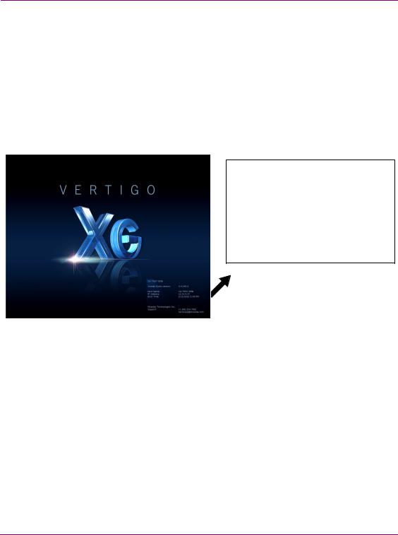
Vertigo XG’s desktop - device identification
To easily identify the active device, the Vertigo XG’s desktop features the Vertigo XG logo, as well as identification information related specifically to the Vertigo XG device (figure 3-1). Specifically, the information presented are:
•The Vertigo Suite software version that the Vertigo XG device is currently running
•The host name given to the Vertigo XG device
•The IP Address currently assigned to the Vertigo XG device
•The date and time at which the Vertigo XG device was last started
•Technologies Technical Support contact information
XG-Embedded
Xmedia Suite version: 5.0.XXX.0
Host Name: XG-Embedded
IP Address: 10.14.4.15
Boot Time: 11/15/2014 11:32 AM
Grass Valley, A Belden Brand
Support: +1.800.224.7882
techsupp@grassvalley.com
Figure 3-1. The Vertigo XG’s desktop displays the device’s identification information
3-2 |
Vertigo XG Configuration Guide |
Vertigo XG’s Desktop Applications & Tools
Vertigo XG Control Panel and XG Dashboard
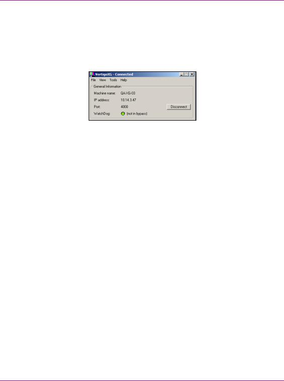
When the Vertigo XG is started, the Vertigo XG Control Panel is automatically opened on the desktop (figure 3-2). The Control Panel is a simple user interface that allows you to quickly reference general information about the Vertigo XG device, as well as perform basic tasks for operating the Vertigo XG like, loading a scene and launching the XG Dashboard application.
Figure 3-2. The Vertigo XG’s Control Panel
The following tables provides descriptions of the commands and fields on the Vertigo XG’s Control Panel:
GENERAL INFORMATION |
These read-only fields display information regarding the local host |
|
|
computer that is being used to run/control the Vertigo XG device. |
|
|
• MACHINE NAME: Name of the host computer. |
|
|
• IP ADDRESS: The IP address of the host computer. |
|
|
• PORT: The port number that is dedicated to the Vertigo XG. |
|
|
• WATCHDOG: The Watchdog field on the Vertigo XG’s Control Panel |
|
|
displays a colored LED along with a brief description indicating its |
|
|
status. |
|
|
The possible states for the Vertigo XG’s Watchdog are: |
|
|
• GREEN - not in bypass |
|
|
• YELLOW – bypass is active – nothing to render |
|
|
• YELLOW – bypass is active – user triggered |
|
|
• RED – bypass is active – other channel failed |
|
|
• RED – bypass is active – D3D error |
|
|
• RED – bypass is active – error |
|
|
• |
GREY – Disabled |
|
• |
GREY – Ignored |
|
|
|
DISCONNECT button |
Promptly closes the connection between the Vertigo XG device and the |
|
|
application that it was actively connected to. |
|
|
|
|
Vertigo XG Configuration Guide |
3-3 |

Vertigo XG’s Desktop Applications & Tools
FILE menu • Open - Launches the OPEN dialog box, allowing you to select and load a scene to the Vertigo XG device. The directory that the Open dialog box opens is set in the PUBLISH PATH parameter on Dashboard’s GENERAL page. The default directory location for Vertigo XG scenes is F:\Scene. Please see “XPublish Agent Control Panel” on page 3-15 for instructions about how to properly set the publish path directories.
•Exit - Closes the Vertigo XG’s Control Panel window. See “Windows Explorer” on page 3-12 for instructions on how to reopen a Control Panel if it was accidently closed.
VIEW menu |
• Open Log File - Launches the device’s current log file in a text editor |
|
(Notepad). Note that Logging must be enabled in Dashboard for this |
|
menu command to work. |
|
|
TOOLS menu |
• Launch Dashboard - Opens the XG Dashboard, which is an |
|
application that allows you to configure the settings and behavior of |
|
Vertigo devices, including the Vertigo XG (see “Dashboard - |
|
Vertigo XG’s Local Configuration Software” on page 5-1). |
|
• Identify - Displays the device’s identity data on its output. When |
|
enabled, the machine name, IP address and command port are |
|
displayed on the Vertigo XG’s output. Note that the identity |
|
information appears on the output, even if on-air. Therefore, it should |
|
be used for diagnostics and troubleshooting tasks only, and then |
|
disabled. |
|
|
HELP menu |
• About - Opens the About Vertigo XG window, which displays the |
|
version of the Vertigo Suite software that is currently running on the |
|
device. |
3-4 |
Vertigo XG Configuration Guide |
Vertigo XG’s Desktop Applications & Tools
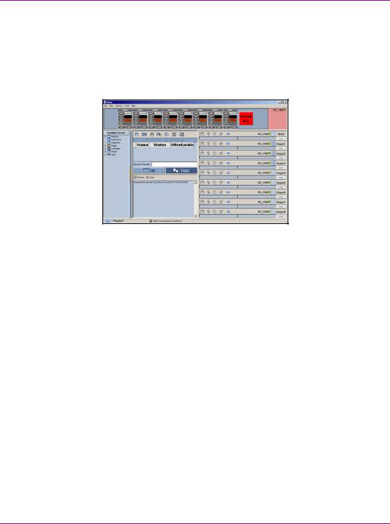
Xplay - Playout control application
When the Vertigo XG is started, the Xplay application automatically opens on the desktop (figure 3-3). Xplay is the playout control application that the master control system or device uses to control the playout of video and graphics on the Vertigo XG device. The master control system/device and Xplay communicate with each other using industry standard automation protocols.
Figure 3-3. Xplay
The Xplay User Manual provides instructions and complete information regarding configuring Xplay. Once Xplay is initially configured, you should not have to interact any further with the Xplay application.
For general information, the following sections provide brief descriptions of the Xplay components and/or settings that are relevant to the interaction of the Xplay with a master control system or device:
•“Device Manager” on page 3-6
•“Automation Configuration” on page 3-8
•“Xplay’s Automation settings” on page 3-9
Vertigo XG Configuration Guide |
3-5 |
Loading...