


 Loading...
K-FRAME
VIDEO PRODUCTION CENTER
Installation Planning Guide
071887504 NOVEMBER 2014

CERTIFICATE
Certificate Number: 510040.001
The Quality System of:
Grass Valley USA, LLC and its Grass Valley Affiliates
Headquarters: |
|
400 Providence Mine Road |
15655 SW Greystone Ct. |
Nevada City, CA 95945 |
Beaverton, OR 97006 |
United States |
United States |
Kapittelweg 10 |
2300 So. Decker Lake Blvd. |
4827 HG Breda |
Salt Lake City, UT 84119 |
The Nederlands |
United States |
Including its implementation, meets the requirements of the standard:
ISO 9001:2008
Scope:
The design, manufacture and support of video and audio hardware and software products and related systems.
This Certificate is valid until: |
June 14, 2015 |
This Certificate is valid as of: |
June 14, 2012 |
Certified for the first time: |
June 14, 2000 |
H. Pierre Sallé
President
DEKRA Certification, Inc
The method of operation for quality certification is defined in the DEKRA General Terms And Conditions For Quality And Environmental Management Systems Certifications. Integral publication of this certificate is allowed.
DEKRA Certification, Inc. |
Accredited By: |
4377 County Line Road |
ANAB |
Chalfont, PA 18914 |
|
Ph: (215)997-4519 |
|
Fax: (215)997-3809 |
|
CRT 001 042108
K-FRAME
VIDEO PRODUCTION CENTER
Installation Planning Guide
071887504 NOVEMBER 2014
Contacting Grass Valley
International |
France |
+800 8080 2020 or +33 1 48 25 20 20 |
|
United States/Canada |
+1 800 547 8949 or +1 530 478 4148 |
Support Centers |
24 x 7 |
|
|
24 x 7 |
|
|
|
Hong Kong, Taiwan, Korea, Macau: +852 2531 3058 Indian Subcontinent: +91 22 24933476 |
|||
|
Asia |
Southeast Asia/Malaysia: +603 7492 3303 Southeast Asia/Singapore: +65 6379 1313 |
|||
Local Support |
|
China: +861 0660 159 450 Japan: +81 3 5484 6868 |
|
||
|
|
|
|
|
|
Centers |
Australia and New Zealand: +61 1300 721 495 |
|
Central/South America: +55 11 5509 3443 |
||
(available |
Middle East: +971 4 299 64 40 Near East and Africa: +800 8080 2020 or +33 1 48 25 20 20 |
||||
during normal |
|
|
|
|
|
business hours) |
|
Belarus, Russia, Tajikistan, Ukraine, Uzbekistan: +7 095 2580924 225 Switzerland: +41 1 487 80 02 |
|||
|
Europe |
S. Europe/Italy-Roma: +39 06 87 20 35 28 -Milan: +39 02 48 41 46 58 S. Europe/Spain: +34 91 512 03 50 |
|||
|
Benelux/Belgium: +32 (0) 2 334 90 30 Benelux/Netherlands: +31 (0) 35 62 38 42 1 N. Europe: +45 45 96 88 70 |
||||
|
|
Germany, Austria, Eastern Europe: +49 6150 104 444 UK, Ireland, Israel: +44 118 923 0499 |
|||
|
|
|
|
|
|
Copyright
Copyright © 2014 Grass Valley. All rights reserved. This product may be covered by one or more U.S. and foreign patents.
Belden, Belden Sending All The Right Signals, and the Belden logo are trademarks or registered trademarks of Belden Inc. or its affiliated companies in the United States and other jurisdictions. Grass Valley trademarks or registered trademarks of Grass Valley. Belden Inc., Grass Valley, and other parties may also have trademark rights in other terms used herein.
Recycling
Visit www.grassvalley.com for recycling information.
4 |
K-FRAME — Installation Planning Guide |
Contents
Copyright . . . . . . . . . . . . . . . . . . . . . . . . . . . . . . . . . . . . . . . . . . . . . . . . . . . . . . . . . . . 4
Recycling. . . . . . . . . . . . . . . . . . . . . . . . . . . . . . . . . . . . . . . . . . . . . . . . . . . . . . . . . . . . 4
Section 1 — Introduction. . . . . . . . . . . . . . . . . . . . . . . . . . . . . . . . . . . . . . . . . . . . . . . . . 7
Overview . . . . . . . . . . . . . . . . . . . . . . . . . . . . . . . . . . . . . . . . . . . . . . . . . . . . . . . . . . . . . 7
Features. . . . . . . . . . . . . . . . . . . . . . . . . . . . . . . . . . . . . . . . . . . . . . . . . . . . . . . . . . . . . . . 8
General . . . . . . . . . . . . . . . . . . . . . . . . . . . . . . . . . . . . . . . . . . . . . . . . . . . . . . . . . . . . . 8
K-Frame Standard Frame . . . . . . . . . . . . . . . . . . . . . . . . . . . . . . . . . . . . . . . . . . . . . . 9
K-Frame Compact Frame . . . . . . . . . . . . . . . . . . . . . . . . . . . . . . . . . . . . . . . . . . . . . . 9
K-Frame Compact S-series Frame (Differences) . . . . . . . . . . . . . . . . . . . . . . . . . . 10
K-Frame Video Processor. . . . . . . . . . . . . . . . . . . . . . . . . . . . . . . . . . . . . . . . . . . . . . . 10
K-Frame Control Surfaces . . . . . . . . . . . . . . . . . . . . . . . . . . . . . . . . . . . . . . . . . . . . . . 10
Kayenne . . . . . . . . . . . . . . . . . . . . . . . . . . . . . . . . . . . . . . . . . . . . . . . . . . . . . . . . . . . 10
Flat or Curved Control Panel Orientation . . . . . . . . . . . . . . . . . . . . . . . . . . . . . 12
Control Panel Stripes. . . . . . . . . . . . . . . . . . . . . . . . . . . . . . . . . . . . . . . . . . . . . . . 13
Touch Screen Menu Panel . . . . . . . . . . . . . . . . . . . . . . . . . . . . . . . . . . . . . . . . . . 13
Karrera. . . . . . . . . . . . . . . . . . . . . . . . . . . . . . . . . . . . . . . . . . . . . . . . . . . . . . . . . . . . . 14
Touch Screen Menu Panel Option. . . . . . . . . . . . . . . . . . . . . . . . . . . . . . . . . . . . 14
Soft Panel (KSP) Option . . . . . . . . . . . . . . . . . . . . . . . . . . . . . . . . . . . . . . . . . . . . . . 15
Menu Application . . . . . . . . . . . . . . . . . . . . . . . . . . . . . . . . . . . . . . . . . . . . . . . . . . . 16
Kayenne K-Frame System Examples . . . . . . . . . . . . . . . . . . . . . . . . . . . . . . . . . . . . . 16
Basic Single Suite Kayenne Panel System . . . . . . . . . . . . . . . . . . . . . . . . . . . . . . . 16
Multiple Suite Kayenne Panel System . . . . . . . . . . . . . . . . . . . . . . . . . . . . . . . . . . 16
Karrera K-Frame System Examples . . . . . . . . . . . . . . . . . . . . . . . . . . . . . . . . . . . . . . 17
Basic Single Suite Karrera Panel System . . . . . . . . . . . . . . . . . . . . . . . . . . . . . . . . 17
Multiple Suites and Control Surfaces . . . . . . . . . . . . . . . . . . . . . . . . . . . . . . . . . . . 18
Supported Control Protocols. . . . . . . . . . . . . . . . . . . . . . . . . . . . . . . . . . . . . . . . . . . . 19
Section 2 — K-Frame Installation . . . . . . . . . . . . . . . . . . . . . . . . . . . . . . . . . . . . . . 21
13-RU Video Processor. . . . . . . . . . . . . . . . . . . . . . . . . . . . . . . . . . . . . . . . . . . . . . . . . 21 6-RU Video Processors . . . . . . . . . . . . . . . . . . . . . . . . . . . . . . . . . . . . . . . . . . . . . . . . . 26 6RU Compact S-series Front Views with Doors Removed . . . . . . . . . . . . . . . . . 28 6RU Compact Front Views with Doors Removed . . . . . . . . . . . . . . . . . . . . . . . . 29 6RU Rear View . . . . . . . . . . . . . . . . . . . . . . . . . . . . . . . . . . . . . . . . . . . . . . . . . . . . . . . 30 K-Frame Controller Connections . . . . . . . . . . . . . . . . . . . . . . . . . . . . . . . . . . . . . . . . 30 K-Frame Standard Power Supply Frame Installation . . . . . . . . . . . . . . . . . . . . . . . 31 K-Frame Standard Power Supply Frame Rack Placement . . . . . . . . . . . . . . . . . 32 K-Frame Standard Power Supply Cooling . . . . . . . . . . . . . . . . . . . . . . . . . . . . . . 34 K-Frame Standard Power Supply AC Requirements. . . . . . . . . . . . . . . . . . . . . . 34 Supplied Power Cables for Standard K-Frame . . . . . . . . . . . . . . . . . . . . . . . . . 34 About Low Line (120V) Operational Considerations. . . . . . . . . . . . . . . . . . . . 35 About High Line (208V-240V) Verses Low Line (120V) Operations . . . . . . . 35 K-Frame Compact Power Supply AC Requirements . . . . . . . . . . . . . . . . . . . . . . . 36 About Low Line (120V) Operational Considerations . . . . . . . . . . . . . . . . . . . . . 36 About High Line (208V-240V) Verses Low Line (120V) Operations . . . . . . . . . 36 Replacing Compact Power Supplies . . . . . . . . . . . . . . . . . . . . . . . . . . . . . . . . . . . . . 37 K-Frame Video Processor Door Removal Clearance . . . . . . . . . . . . . . . . . . . . . . . . 38
K-FRAME — Installation Planning Guide |
5 |
Contents
Section 3 — K-Frame Cabling . . . . . . . . . . . . . . . . . . . . . . . . . . . . . . . . . . . . . . . . . . 41
Overview . . . . . . . . . . . . . . . . . . . . . . . . . . . . . . . . . . . . . . . . . . . . . . . . . . . . . . . . . . . . 41
Network Cabling . . . . . . . . . . . . . . . . . . . . . . . . . . . . . . . . . . . . . . . . . . . . . . . . . . . . . 42
K-Frame Ethernet Tally Verses Serial Tally . . . . . . . . . . . . . . . . . . . . . . . . . . . . . 42
K-Frame Ethernet Switch. . . . . . . . . . . . . . . . . . . . . . . . . . . . . . . . . . . . . . . . . . . . . 42
Suites and Control Surfaces. . . . . . . . . . . . . . . . . . . . . . . . . . . . . . . . . . . . . . . . . . . 42
Customer Supplied Ethernet Routers and Switches . . . . . . . . . . . . . . . . . . . . . . 43
Factory Default Network Settings . . . . . . . . . . . . . . . . . . . . . . . . . . . . . . . . . . . . . 45
Video Cabling . . . . . . . . . . . . . . . . . . . . . . . . . . . . . . . . . . . . . . . . . . . . . . . . . . . . . . . . 45
Inputs . . . . . . . . . . . . . . . . . . . . . . . . . . . . . . . . . . . . . . . . . . . . . . . . . . . . . . . . . . . . . 46
Outputs. . . . . . . . . . . . . . . . . . . . . . . . . . . . . . . . . . . . . . . . . . . . . . . . . . . . . . . . . . . . 46
MatchDef and SetDef Format Conversion . . . . . . . . . . . . . . . . . . . . . . . . . . . . . . 46
Reference Input . . . . . . . . . . . . . . . . . . . . . . . . . . . . . . . . . . . . . . . . . . . . . . . . . . . . . 46
K-Frame System Video Timing and Delay . . . . . . . . . . . . . . . . . . . . . . . . . . . . . . . . 47
Time Zones and the Autotiming Window . . . . . . . . . . . . . . . . . . . . . . . . . . . . . . 48
Video Processor Frame GPI/Tally Interface . . . . . . . . . . . . . . . . . . . . . . . . . . . . . . 49
GPI and Tally Connections . . . . . . . . . . . . . . . . . . . . . . . . . . . . . . . . . . . . . . . . . . . 49
GPI Inputs. . . . . . . . . . . . . . . . . . . . . . . . . . . . . . . . . . . . . . . . . . . . . . . . . . . . . . . . 49
Tally/GPI Outputs . . . . . . . . . . . . . . . . . . . . . . . . . . . . . . . . . . . . . . . . . . . . . . . . 50
Pin Assignments . . . . . . . . . . . . . . . . . . . . . . . . . . . . . . . . . . . . . . . . . . . . . . . . . . . . . . 52
RS-422/485 Ports. . . . . . . . . . . . . . . . . . . . . . . . . . . . . . . . . . . . . . . . . . . . . . . . . . . . 52
RS-232 Ports . . . . . . . . . . . . . . . . . . . . . . . . . . . . . . . . . . . . . . . . . . . . . . . . . . . . . . . . 52
GPI In, Tally, GPI Out . . . . . . . . . . . . . . . . . . . . . . . . . . . . . . . . . . . . . . . . . . . . . . . 53
Appendix A — Specifications. . . . . . . . . . . . . . . . . . . . . . . . . . . . . . . . . . . . . . . . . . . 55
Index. . . . . . . . . . . . . . . . . . . . . . . . . . . . . . . . . . . . . . . . . . . . . . . . . . . . . . . . . . . . . . . . . . . . . . 59
6 |
K-FRAME — Installation Planning Guide |
Section 1
Introduction
Overview
The Grass Valley K-Frame family of multi-format digital production switchers provides powerful, ground-breaking features designed to meet the widest range of requirements for live studio, mobile, and post-produc- tion applications.
The K-Frame Video Processor is the heart of the system, providing extensive video switching and signal processing capabilities. This functionality is controlled using:
•a Kayenne control surface,
•a Karrera control surface,
•the Soft Panel (KSP option), and/or
•the Menu application running on a PC.
In addition, a K-Frame system supports direct control of external devices (DDRs, Servers) and bi-directional control to and from routing and automation systems.
KAYENNE K-FRAME — Installation & Service Manual |
7 |
Section 1 — Introduction
Features
General
•Fully digital 10-bit 4:2:2 video switcher including Future-Ready 4K and 1080p (level A or B) support.
•Optional smart I/O modules provide up/down/cross-conversion when licensed with SetDef and MatchDef.
•Integrated Macro Builder/Editor allows users to edit macros online or offline on a PC running the menu application.
•Optional DoubleTake™ (split M/E mode) effectively increases the number of M/Es and adds flexibility to Suites operation while FlexiKey™ programmable clean feed mode supports separately programmable configurations of keyers from four M/E outputs.
•Aux bus transitions for dissolves and wipes on aux bus outputs.
•Interfaces with Grass Valley routers and Kaleido Multiviewers and their control systems.
•Optional Integrated Image Store capable of delivering up to 32 GB storage of Stills (3,000 images) or “Movies” (a total of 50 seconds) of 1080p video.
•LDK Series and LDX Series camera control with Ethernet tally via Connect Gateway.
•Optional integrated external ClipStore provides multiple channels of video/key pairs for up to 10+ hours of nonvolatile video/key/audio clip content.
•999 macros with many new ways to recall macros from the Control Panel.
•1,000 E-MEM registers with Define E-MEM for fine control in creation and editing of effects.
•Optional M/E Previewer provides a method to check and monitor any input to an M/E.
•VDCP Ethernet connection for stadium applications.
•Ethernet tally connection for integration with external tally systems.
•Optional RGB color correction on M/E buses and aux bus outputs.
8 |
KAYENNE K-FRAME — Installation & Service Manual |
Features
•Source Rules:
•Links keyers to sources.
•Settings for On/Off/Left Alone on every M/E.
•Full look-ahead preview of rules.
•Hot-swappable, front/rear removable modules and power supplies.
•Optional multiple Multiviewer capability with 5 pre-configured layouts (maximum 14 panes per layout) with On-Air and Preview tally.
K-Frame Standard Frame
•Up to 192 inputs and 96 outputs.
•Up to 9 M/Es, accessible across two suites—by using DoubleTake this may be increased to 18 virtual M/Es.
•Every M/E has six keyers with standard keying modes including Chroma Key, a pool of floating 3D iDPMs, and two frame stores per keyer—the Controller M/E cannot use floating 3D iDPMs.
•2D-DPMs (resizers) on every keyer, with 6 pairs per M/E so iDPMs can be utilized for more complex effects.
•The Controller M/E has a complement of 6 full keyers with Chroma Key and 2D-DPMs.
•Up to 16 iDPMs (Integrated Digital Picture Manipulators), assigned as either floating iDPMs or within an eDPM at user’s discretion.
K-Frame Compact Frame
•Up to 80 inputs and 48 outputs.
•Up to 5 M/Es, accessible across two suites, increased to 10 virtual M/ Es by using DoubleTake.
•Every M/E has six keyers with standard keying modes including Chroma Key, two frame stores per keyer—every keyer except for Controller M/E can use the pool of floating 3D iDPMs.
•2D-DPMs (resizers) on every keyer.
•The Controller M/E has a complement of 6 full keyers with Chroma Key and 2D-DPMs.
•Up to 8 iDPMs (Integrated Digital Picture Manipulators), assigned as either floating iDPMs or within an eDPM at user’s discretion.
KAYENNE K-FRAME — Installation & Service Manual |
9 |
Section 1 — Introduction
K-Frame Compact S-series Frame (Differences)
•Up to 6 M/Es, accessible across two suites, increased to 12 virtual M/Es by using DoubleTake.
•Every M/E has four keyers with standard keying modes including Chroma Key and every keyer can use the pool of floating 3D iDPMs (Key Stores are not available).
•2D-DPMs (resizers) on every keyer.
•Controller M/E replaced by a pair of Multiviewers with pre-configured layouts and On-Air/Preview tally.
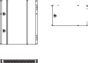
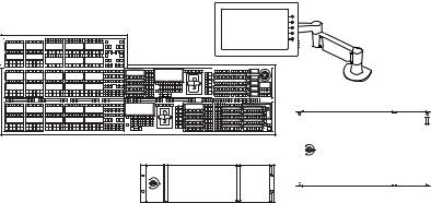
K-Frame Video Processor
The K-Frame Video Processor is available in two sizes, the 13RU Standard and the 6RU Compact. The number of licensed boards present in the frame determines the number of MEs available, as well as the number of video inputs, outputs, GPIOs and Relay Tallies.
Figure 1. K-Frame Video Processors |
|
|
|
|
|
|
||
K-Frame 13-RU |
|
|
|
|
|
|
||
Video Processor |
|
K-Frame 6-RU |
||||||
|
|
|
Video Processor |
|||||
|
|
|
||||||
|
|
|
|
|
|
|
|
|
|
|
|
|
|
|
|
|
|
|
|
|
|
|
|
|
|
|
|
|
|
|
|
|
|
|
|
|
|
|
|
|
|
|
|
|
Integrated Power Supplies
Frame Power Supply 1-RU (For Standard K-Frame only)
8875_01r1
K-Frame Control Surfaces
Kayenne
A Kayenne control surface typically consists of a Control Panel, a Menu Panel with an included articulated support arm, a Panel Control Unit (PCU) frame, and optional Satellite Panels. This control surface has an
10 |
KAYENNE K-FRAME — Installation & Service Manual |
K-Frame Control Surfaces
innovative modular design. Representative Kayenne control surfaces are shown in the following illustrations.
Figure 2. Kayenne 4-ME 35 Control Surface
4-ME 35 Control Panel |
Menu Panel |
|
Menu Panel |
|
Articulated |
|
Arm |
|
Optional |
|
Module |
|
Optional Device |
|
Control Module |
Panel Control Unit (PCU)
8623266_01
Figure 3. Kayenne 3-ME 35 Control Surface |
|
|
3-ME 35 Control Panel |
Menu Panel |
|
Optional Device |
Menu Panel |
|
Articulated |
||
Control Module |
||
Arm |
||
|
||
|
Panel Control Unit (PCU) |
|
|
8623266 02 |
Figure 4. Kayenne 2-ME 25 Control Surface
2-ME 25 Control Panel |
Menu Panel |
Menu Panel |
|
|
|
|
|
Articulated |
|
|
Arm |
|
Panel Control Unit (PCU) |
|
|
|
8623266_03 |
Figure 5. Kayenne 1-ME 15 Control Surface |
|
|
1-ME 15 Control Panel |
Menu Panel |
|
|
Menu Panel |
|
|
Articulated |
|
|
Arm |
Panel Control Unit (PCU) |
8623266_04
KAYENNE K-FRAME — Installation & Service Manual |
11 |
Section 1 — Introduction
The modular design and use of a separate PCU supports the hot-replace- ment of individual Control Panel components, if necessary, while the rest of the system remains operational.
CAUTION Do not connect or disconnect the PCU to Control Panel cables while the system is powered on.
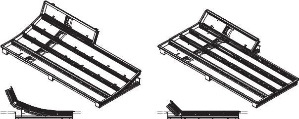
Flat or Curved Control Panel Orientation
The main Kayenne Control Panel supports different physical orientations. Besides a conventional flat surface, a special support design permits a curved working surface, where the MEs progressively tilt for improved ergonomics.
Figure 6. Curved and Flat Control Surface Installations
Curved Control Panel Assembly |
Flat Control Panel Assembly |
8623266_36
12 |
KAYENNE K-FRAME — Installation & Service Manual |

K-Frame Control Surfaces
Control Panel Stripes
The main Kayenne Control Panel is organized into from one to five Stripes. Each Stripe consists of a tray and its complement of drop-in modules. An ME Stripe has a module for Source Selection, Transition, and individual E-MEM control. Additional Master E-MEM, Machine Control, Multi-Func- tion, and Local Aux modules are populated to complete the control surface functionality.
Figure 7. Portion of Control Panel ME Stripe
Hold |
Key |
Key |
Key |
Macro |
Ptn |
EMEM |
Trans |
EMEM |
|
1 |
3 |
5 |
|
Limit |
Run |
Rate |
|
|
|
|
|
|
|
|
Key1 |
Key1 |
|
|
|
|
|
|
|
Cut |
Auto |
|
|
|
|
|
|
|
|
|
|
|
Panel |
Trans |
|
Key |
Far |
|
|
Aux |
|
|
|
|
|
|
Mem |
Rate |
|
Split |
|
|
|
|
|
|
|
|
|
Key2 |
Key2 |
|
|
|
|
|
|
|
|
|
|
|
|
|
|
||
|
|
|
|
|
|
|
|
|
|
Cut |
Auto |
|
|
|
|
|
|
|
|
|
|
|
|
|
|
Menu |
|
Hold |
Key |
Key |
Key |
Rtr |
|
|
|
|
|
Key3 |
Key3 |
|
|
|
2 |
4 |
6 |
|
|
|
|
|
|
Cut |
Auto |
|
|
|
|
|
|
Key |
Key |
Key |
Key |
Key |
Key |
Key |
Macro |
Auto |
|
|
|
|
|
Prior |
1 |
2 |
3 |
4 |
5 |
6 |
Key4 |
Run |
|
|
|
|
|
|
|
|
|
|
|
Key4 |
|
|
|
Pri |
Sec |
|
Rules |
EMEM |
|
|
|
|
|
Cut |
Auto |
|
|
|
|
|
Hold |
|
Mix |
|
User |
User |
User |
Trans |
|
Rev |
54 |
|
|
|
|
|
|
|
1 |
2 |
3 |
PVW |
Key5 |
|
|
|
|
|
|
|
|
|
|
|
|
Key5 |
|
||
|
|
|
|
|
|
|
|
|
|
Cut |
Auto |
|
_ |
Hold |
A |
U1 |
|
|
Wipe |
Wipe |
User |
User |
User |
Pst |
|
Rwd |
8623266 |
|
|
|
|
|
1 |
2 |
4 |
5 |
6 |
BLK |
Key6 |
|
|
|
|
|
|
|
|
|
|
|
|
Key6 |
|
|
|
|
|
|
|
|
|
|
|
|
|
Cut |
Auto |
|
|
Hold |
B |
U2 |
|
|
Cut |
|
Auto |
|
|
|
|
Run |
|
Source Module (35, 25, or 15) Transition Module Local E-MEM Module
Touch Screen Menu Panel
Each Kayenne control surface includes a Menu Panel that features a wide format 15 in. touch screen display. An articulated arm is also included, offering a wide variety of installation options. The Menu Panel has a standard VESA-75 hole pattern and M4 threads, compatible with this and many other mounting devices.
The Menu Panel has four USB ports, two on the right side edge of the panel and two on the back for keyboard and mouse (wired or wireless are supported).
Figure 8. Menu Panel with Articulated Arm
8623266_05
KAYENNE K-FRAME — Installation & Service Manual |
13 |

Section 1 — Introduction
Karrera
A Karrera control surface typically consists of a Control Panel and a Menu application. Representative Karrera control surfaces are shown in the following illustrations.
Figure 9. Karrera 3-ME 35 Control Surface
Karrera 3-ME 35 Control Panel
Optional Touch Screen
Karrera Menu Panel with
Fanless PC
Menu Panel
Articulated
Arm
8623266_02_Krr
Figure 10. Karrera 2-ME 25 Control Surface
Karrera 2-ME 25 Control Panel |
|
Karrera Menu on PC |
|
|
|
|
|
|
(Customer Supplied PC)
8623266_03_Krr
Touch Screen Menu Panel Option
A hardware Karrera Menu Panel is available as an option, which features a wide format 15 in. touch screen display. An articulated arm is also included, offering a wide variety of installation options.
Figure 11. Menu Panel with Articulated Arm
8623266_05_Krr
14 |
KAYENNE K-FRAME — Installation & Service Manual |
K-Frame Control Surfaces
The Menu Panel has a standard VESA-75 hole pattern and M4 threads, compatible with this and many other mounting devices. The Menu Panel also has four USB ports, two on the right side edge of the panel and two on the back for keyboard and mouse (wired or wireless are supported).
A fanless PC, running Windows OS, is available which mounts behind the Menu Panel.
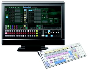
Soft Panel (KSP) Option
Figure 12. Soft Panel Application
The KSP is an optional 1-ME Soft Panel GUI which provides direct control of switching crosspoints, recalling effects and macros together with an integrated version of the Menu application. A customized PC keyboard is included with the option for users who like quick cut and mix action from a hard-button interface. The KSP can be used as an adjunct to a main panel, providing a second seat (second control surface) in a Suite, or as the only control surface for a second Suite.
The KSP GUI application is designed to run on a PC platform. The screen must be 1920x1080 resolution or better (which is common in professional video environments). A touchscreen is not required, but can be very useful.
The KSP software is included with the switcher application software. Purchasing the option provides a software license that enables the interface for the selected switcher, and includes a customized PC keyboard. The license activates an unlimited number of KSP applications associated with the licensed video processor frame. Additional customized PC keyboards are also available for purchase.
KAYENNE K-FRAME — Installation & Service Manual |
15 |
Section 1 — Introduction
Menu Application
The Menu application software provided with every K-Frame system can be run on a standard PC. This software accesses all the system’s functionality, permitting mouse and keyboard control from a laptop, or remote control from any location on the network.
Kayenne K-Frame System Examples
Basic Single Suite Kayenne Panel System
A basic K-Frame system consists of a Control Panel, a Menu application running on a touch screen Menu Panel, and a Video Processor Frame. The Control Panel and Menu application make up a control surface associated with that frame. The Kayenne Control Panel and Menu Panel have associated active electronics housed in the Panel Control Unit (PCU).
Figure 13. Kayenne Single Suite Compact Frame Example
Menu Panel
2-ME 25 Kayenne Control Panel
Panel Control Unit (PCU)
Compact 6-RU K-Frame


 8877_01
Multiple Suite Kayenne Panel System
A K-Frame system can be subdivided into two suites, if desired, each of which can have two control surfaces (Surface A and Surface B). Each surface has it's own set of Panel Preferences for configuration of the control panel behavior and independent macro systems to allow for independent building and running of macros by each operator at the control surface. Hardware resources in the Video Processor Frame can be assigned to an individual suite during configuration, essentially creating two separate switchers sharing one frame.
16 |
KAYENNE K-FRAME — Installation & Service Manual |
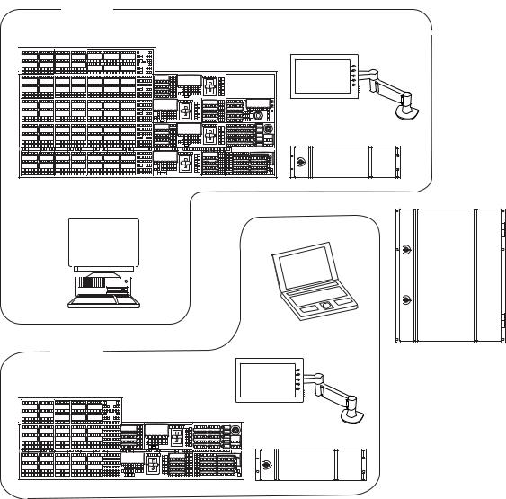
Karrera K-Frame System Examples
Figure 14. Kayenne Multi-Suite Standard Frame Example
Suite 1
4-ME 35 Kayenne Control Panel
KSP 1-ME
Soft Panel Option
(Keyboard Included)
(Customer Supplied PC)
Suite 2
2-ME 25 Kayenne Control Panel
Menu Panel
Panel Control Unit (PCU)
Menu on PC
(Customer Supplied PC)
Menu Panel
Standard 13-RU
K-Frame
Panel Control Unit (PCU)
8875_20
Karrera K-Frame System Examples
Basic Single Suite Karrera Panel System
A basic K-Frame system consists of a Control Panel, a Menu application running on a PC, and a Video Processor Frame. The Control Panel and Menu application make up a control surface associated with that frame.
KAYENNE K-FRAME — Installation & Service Manual |
17 |
Section 1 — Introduction
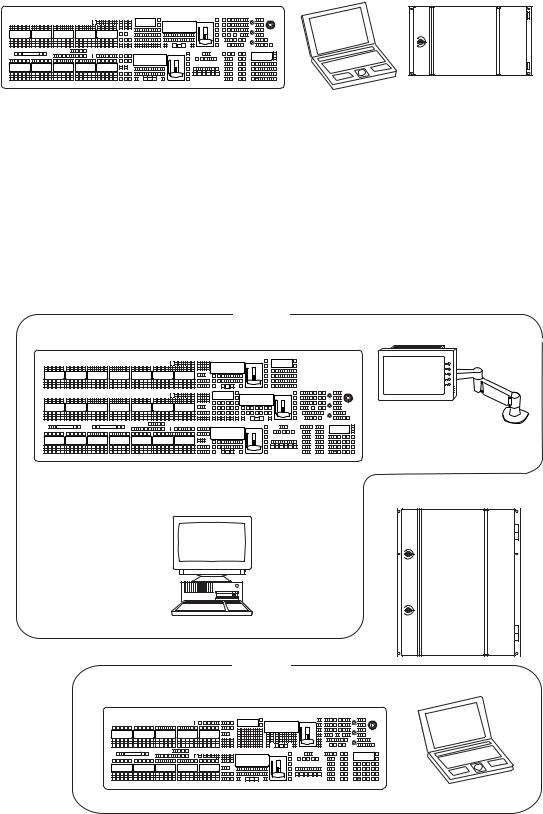
Figure 15. Karrera Single Suite Compact Frame Example
Karrera 2-ME 25 Control Panel |
Karrera Menu on PC |
Compact 6-RU K-Frame |
|
||
|
|
8875_19 |
|
(Customer Supplied PC) |
|
Multiple Suites and Control Surfaces
A K-Frame system can be subdivided into two suites, if desired, each of which can have two control surfaces. Hardware resources in the Video Processor Frame can be assigned to an individual suite during configuration, essentially creating two separate switchers sharing one K-Frame.
Figure 16. Karrera Multi-Suite Standard Frame Example
Suite 1
Karrera 3-ME 35 Control Panel
KSP 1-ME
Soft Panel Option
(Keyboard Included)
(Customer Supplied PC)
Suite 2
Karrera 2-ME 25 Control Panel
Optional Touch Screen Karrera Menu Panel with with Fanless PC and Articulated Arm
Standard 13-RU
K-Frame
8878_01
Karrera Menu on PC
(Customer Supplied PC)
18 |
KAYENNE K-FRAME — Installation & Service Manual |
Supported Control Protocols
Supported Control Protocols
•PBus II
•GPI Inputs and Outputs
•Serial BVW-75 for VTR control
•Odetics protocol for VTR control
•AMP (advanced media protocol) for Profile PVS, Profile XP Media Platform, K2, M-Series, Turbo iDDR, and T2 iDDR systems over Ethernet
•Grass Valley Native Protocol for routers/routing control systems (Trinix/Trinix NXT, Venus™, Triton™, and third-party routers; Jupiter and Encore router control systems)
•Tally (contact closure)
•K-Frame Ethernet Tally protocol
•Ethernet CPL to control Grass Valley external remote AUX Panels
•Grass Valley Editor protocol
•SNMP system monitoring
•Serial and Ethernet VDCP
•LDK Series & LDX Series™ camera control with Ethernet tally via Connect Gateway
KAYENNE K-FRAME — Installation & Service Manual |
19 |
Loading...